New and Changed Information
The following table provides an overview of the significant changes to this document.
|
Cisco NDB Release Version |
Feature |
Description |
|---|---|---|
|
3.9, 3.9.2 |
NetFlow |
This document has details of how to generate NetFlow records. |
NetFlow
NetFlow identifies packet flows for ingress IP packets and provides statistics based on these packet flows. NetFlow does not require any change to either the packets themselves or to any networking device.
NetFlow uses flows to provide statistics for accounting, network monitoring, and network planning. A flow is a unidirectional stream of packets that arrives on a source interface (or VLAN) and has the same values for the keys. A key is an identified value for a field within the packet. You create a flow using a flow record to define the unique keys for your flow. All key values must match for the packet to count in a given flow. A flow might gather other fields of interest, depending on the export record version that you configure. Flows are stored in the NetFlow cache.
You can export the data that NetFlow gathers for your flow by using a flow exporter and export this data to a remote NetFlow Collector, such as Cisco Stealthwatch.
NetFlow can be used for:
-
Network Monitoring- Businesses and users can utilize flow-based analysis techniques to visualize traffic patterns throughout the entire network.
-
Network Planning- Network team can use NetFlow to track and anticipate network growth. For example, they can plan upgrades to increase the number of ports, routing devices or higher-bandwidth interfaces needed to meet growing demand.
-
Security Analysis- With NetFlow, security teams can detect changes in network behavior to identify anomalies indicative of a security breach.
Cisco Nexus Data Broker and NetFlow
Benefits of using NetFlow on NDB switches:
-
Cisco NDB can be used to collect NetFlow on SPAN/TAP traffic and export the packets to the Flow collector.
It is not mandatory to configure NetFlow on production switches to generate NetFlow records. Cisco NDB can augment this functionality by generating records on the SPAN/ TAP traffic.
-
NetFlow and Tap aggregation can be implemented and operational at the same time.
-
NetFlow records are exported via the management interface; another separate interface for the Flow collector is not required.
-
NetFlow records are generated on the non-sampled packets at the line rate in the ASIC hardware.
-
Layer2 and Layer3 flow records can be collected on the incoming traffic.
-
NetFlow v9 records are generated in compliance with IPFIX.
NetFlow is supported on Cisco NDB from Release 3.8. The supported platforms and minimum supported NX-OS versions are:
|
Nexus Platform |
NX-OS Release |
|---|---|
|
9300-FX |
7.0(3)I7(1) |
|
9300-EX |
7.0(3)I7(2) |
|
9336C-FX2 and 93240YC-FX2 |
7.0(3)I7(3) |
|
9500 with EX line cards |
9.2(2) |
|
9500 with FX line cards |
9.3(1) |
Prerequisites for Configuring NetFlow
Prrequisites for configuring NetFlow on NDB switches:
-
NetFlow collector should be reachable from the NX-OS NDB switch via the management interface (mgmt vrf); ensure proper routes are configured on the NDB switch.
 Note |
NetFlow requires Essential license on the NDB switches. For a complete explanation of the Cisco NX-OS licensing scheme, see the Cisco NX-OS Licensing Guide. |
Generating NetFlow Records Use Case Overview
This section describes how to generate and collect NetFlow records on copy packets (obtained through SPANS or optical TAPs) and export them to the NetFlow collector.
Based on the NetFlow record configured on the switch, records are collected from the incoming flows. Based on the NetFlow Exporter configurations, configured using the Cisco NDB UI, the collected records are sent to the flow collector via the management interface.
NDB Version- 3.9.0
NX-OS version - 9.3(5)
Cisco Nexus Switch - N9K-C93180YC-EX
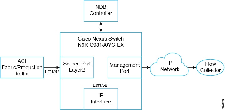
Topology details:
-
Input port—Eth1/37; ingress port- traffic from ACI/ production traffic
-
IP interface port—Eth1/52; layer3 port- this port serves as the source IP address for the NetFlow packets
-
Management port—mgmt 0; egress port- NetFlow records are sent to the flow collector
Configuring NetFlow
Use this procedure to configure NetFlow and export flow records to the NetFlow collector(s).
Note |
The NDB GUI may vary based on the NDB version; there may be slight changes in the procedure, accordingly. For the detailed procedure, you can refer the release-specific NDB configuration guide. |
Before you begin
Create an L3 interface (on the IP interface Eth1/52) using the no switchport command.
Procedure
| Step 1 |
Log into the NDB GUI. |
| Step 2 |
Navigate to Configuration > Port Definitions > Configure Node. |
| Step 3 |
In the Node Configuration window that is displayed, click Configure NetFlow. |
| Step 4 |
In the Configure NetFlow window that is displayed, configure the following NetFlow parameters. |
What to do next
Adding a NetFlow Record
Use this procedure to add a NetFlow record.
Procedure
| Step 1 |
In the Configure NetFlow screen, click Add Record. |
||
| Step 2 |
Enter the Record Name and Description. |
||
| Step 3 |
On the right hand side, select the Match criteria. Check the required check boxes. The selected fields from the packet are matched.
|
||
| Step 4 |
Check the required check boxes under Collect to indicate the data to be collected. |
||
| Step 5 |
Click Submit to create a record. |
What to do next
Use the show running-config netflow to check the configuration for NetFlow record.
flow record Record_01
	description IP_Record
	match ipv4 source address
	match ipv4 destination address
	match ip protocol
	match ip tos
	match transport source-port
	match transport destination-port
	collect counter bytes
	collect counter packets
	collect ip version
Adding a NetFlow Exporter
Use this procedure to add a NetFlow exporter.
Procedure
| Step 1 |
In the Configure NetFlow screen, click Add Exporter. |
| Step 2 |
Enter a Name, Description, Destination (NetFlow collector IP address). |
| Step 3 |
Select the source port for the drop-down list, which is the Layer 3 IP interface (ingress port for ACI/ production traffic). |
| Step 4 |
You may enter the details for the other optional fields (UDF Port, DSCP, Version). |
| Step 5 |
Click Submit to create an exporter. |
What to do next
Use the show running-config netflow to check the configuration for NetFlow exporter.
flow exporter Exporter_01
	description IP_Exporter
	destination ip_address
	source Ethernet1/52
	version 9
Adding a NetFlow Monitor
Use this procedure to add a NetFlow monitor.
Procedure
| Step 1 |
In the Configure NetFlow screen, click Add Monitor. |
||
| Step 2 |
Enter a Name and Description. |
||
| Step 3 |
Select a record from the drop-down list. |
||
| Step 4 |
Select an exporter from the drop-down list. You can choose a maximum of two exporters for a monitor. |
||
| Step 5 |
Click Submit to create a monitor.
|
What to do next
Use the show running-config netflow to check the configuration for NetFlow monitor. The selected criteria is displayed on the switch.
flow monitor Monitor_01
	description IP_Monitor
	record Record_01
	exporter Exporter_01
Creating a Source Port
Use this procedure to create a source port.
Procedure
| Step 1 |
Log into the NDB GUI. |
||
| Step 2 |
Navigate to Configuration . A list of ports available to be configured as source ports are displayed. |
||
| Step 3 |
Click the port you want to configure (Eth 1/37). The details of the selected port are displayed in the Configure Ports pane on the right. |
||
| Step 4 |
Select Edge-Port SPAN from the drop-down list. |
||
| Step 5 |
Enter the Port Description. |
||
| Step 6 |
Enter the VLAN ID as 250.
|
||
| Step 7 |
Select the NetFlow Monitor from the drop-down list. |
||
| Step 8 |
Click Submit to create the source port. Use the show running-config command to check the configuration on the source port (Eth1/37). |
What to do next
-
Configure a static route on the NDB switch to the NetFlow collector using the ip route ip_address mgmt0 ip_address vrf management command.
-
Verify the configurations by generating NetFlow records on NDB.
Send traffic to the ingress port (Eth1/37) and records are collected and exported to the NetFlow collector.
Generating NetFlow Records and Implementing TAP Aggregation Use Case Overview
This section describes how to generate and collect NetFlow records and export them to the NetFlow collector and implement TAP aggregation simultaneously. This is achieved by redirecting traffic to the monitoring tool port.
Based on the NetFlow record configured on the switch, records are collected from the incoming flows. Based on the NetFlow Exporter configurations, configured using the Cisco NDB UI, the collected records are sent to the flow collector via the management interface.
NDB Version- 3.9.0
NX-OS version - 9.3(5)
Cisco Nexus Switch - N9K-C93180YC-EX
Topology
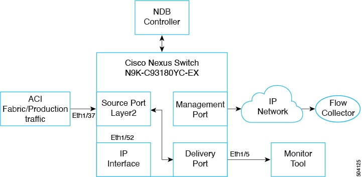
Topology details:
-
Input port—Eth1/37; ingress port- traffic from ACI/ production traffic.
-
IP interface port—Eth1/52; layer3 port- this port serves as the source IP address for the NetFlow packets. Ensure to create an IP interface port manually as NDB cannot configure the same.
-
Management port—mgmt 0; egress port- NetFlow records are sent to the flow collector.
-
Delivery port Eth1/5, from where traffic egresses to the monitoring tool port after filtering, based on set criteria for the packets.
-
A connection needs to be created between Source port Eth1/37 and Delivery port Eth1/5 to redirect the filtered traffic to the monitoring tool port.
Based on the NetFlow record configured on the switch, records are collected from the incoming flows. Based on the NetFlow Exporter configurations, the collected records are sent to Flow Collector via Management interface. NDB switch should be configured with necessary routes to establish the IP reachability to the NetFlow collector.
Configuring NetFlow and Implementing TAP Aggregation Using Port Redirection
For configuring the redirect use-case source port, you need to create a monitor port, filter and connection. The source port creation is discussed above. Follow the complete Configure NetFlow procedure before configuring the following:
-
Monitor port ( monitoring tool port or delivery port)
-
Filter
-
Connection
Note |
The NDB GUI may vary based on the NDB version; there may be slight changes in the procedure, accordingly. For the detailed procedure, you can refer the release-specific NDB configuration guide. |
Creating a Delivery Port
Use this procedure to create a delivery port. Traffic from the source port is sent to the delivery port (after applying relevant filters) from where the traffic egresses to reach the monitoring tool. The delivery port can also be referred to as the monitoring tool port or monitor port.
Procedure
| Step 1 |
Log into the NDB GUI. |
| Step 2 |
Navigate to Configuration > Port Definitions > Port Configuration. |
| Step 3 |
Select the port to be configured as the delivery port and click Configure. |
| Step 4 |
Select Add Monitoring Device and enter a name in the Monitoring Device Name field. |
| Step 5 |
Select the required Switch Node and Port. |
| Step 6 |
Click Submit. |
What to do next
Use the show running-config command to see the configured delivery port details.
Creating a Filter
Use this procedure to create a IP match filter. The created filter enables to send the required (filtered) traffic from the source port to the delivery port (monitoring tool port).
Procedure
| Step 1 |
Log into the NDB GUI. |
| Step 2 |
Navigate to Configuration > Filters. |
| Step 3 |
Click Add Filter. |
| Step 4 |
Enter the required details, such as, Filter Name, Source and Destination IP addresses (source port and delivery port). |
| Step 5 |
Click Add Filter. |
Creating a Connection
Use this procedure to define the link between the source and delivery ports.
Procedure
| Step 1 |
Log into the NDB GUI. |
| Step 2 |
Navigate to Configuration > Connections. |
| Step 3 |
Select New Connection > Add Connection. |
| Step 4 |
Enter details, such as, Connection Name, Filter Details (which was discussed in the previous procedure), Source and Delivery ports. |
| Step 5 |
Click Install Connection. |
What to do next
Use the show runnin-config command to check the connection details. ACE IP redirect configurations are pushed to the source port. Traffic that matches the created IP filter.
 Feedback