
SD-Access and Cisco ACI Integration

Cisco Nexus Dashboard and Cisco DNAC integration allows for automation of a subset of network connectivity and macro segmentation scenarios across Nexus and campus SD-Access fabric deployments. This integration is under limited availability. Please contact your Cisco representative for additional information.
{CiscoSDAFullName} (SD-Access or SDA) is a solution within the Cisco Digital Network Architecture (DNA), which defines a campus-and-branch architecture that implements Cisco’s Intent-Based Networking (IBN) framework. SD-Access defines a uniform policy-based wired and wireless network fabric that meets business needs with security, automation, and assurance. The Cisco Digital Network Architecture Controller (DNAC), in combination with Cisco Identity Services Engine (ISE), is the unified point of automation and management for the SD-Access fabric.
Release 3.7(1) of Cisco Nexus Dashboard Orchestrator (NDO) adds support for {CiscoSDAShortName and } and Cisco ACI integration. The purpose of SD-Access and ACI integration is to securely connect the campus-and-branch network to the data center network. With Release 3.7(1), NDO can perform the following functions:
-
gather network and resource information from both domains
-
automatically configure the VRF-Lite inter-domain connection at the ACI side
-
provide the configuration of the next-hop device connected to the SD-Access border nodes
-
provide cross-domain visibility
Macro Segmentation
The SD-Access and Cisco ACI integration feature of Cisco Nexus Dashboard Orchestrator (NDO) allows macro segmentation of network elements between the ACI domain and the SD-Access domain.
In the ACI domain, entities such as EPGs, subnets, and VLANs are grouped as part of Virtual Routing and Forwarding instances (VRFs). When a VRF requires external communication, the VRF is associated with an IP interface (L3Out) on an ACI Border Leaf (BL). In the SD-Access domain, entities such as users, subnets, and IP pools can be grouped as Virtual Networks (VNs). When a VN requires external communication, the VN is associated with an SD-Access Border Node (BN) interface for IP handoff. The border interfaces of the two domains, ACI and SD-Access, can be physically connected through an IP network (IPN), but this basic connection does not provide connectivity between VRFs and VNs. With Cisco Nexus Dashboard Orchestrator SD-Access and Cisco ACI integration, an administrator can create policies to map (or "stitch") VRFs to VNs.
Macro Segmentation Workflow
A typical {CiscoSDAShortName and } and Cisco ACI integration workflow consists of the following steps, which refer to the figure below.
-
In an existing SD-Access site, a Cisco Digital Network Architecture Controller (DNAC) administrator has configured a campus fabric in which some entities require external access, such as access to the data center. The DNAC administrator has performed the following tasks:
-
created virtual networks (VNs)
-
associated IP address pools to those VNs
-
configured L3 border nodes and associated interfaces
-
created an IP (layer 3) handoff transit network
-
configured Layer-3 handoff for those VNs that need external connectivity
Note that these tasks are normal DNAC administrative tasks and no special modification has been made for {CiscoSDAShortName and } and Cisco ACI integration.
-
-
An NDO operator logs into and onboards the DNAC, using the DNAC credentials.
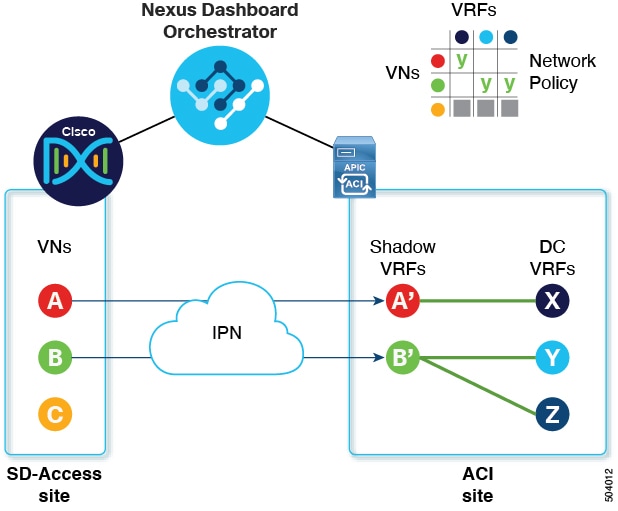
In the onboarding process, NDO automatically accesses the DNAC’s REST API to query for sites, VNs, and border node devices. Upon discovering these entities, NDO learns which VNs are configured for external connectivity (L3 handoff) and on which {CiscoSDAShortName and } border nodes, and it learns their subnets. In the example shown in Macro Segmentation Workflow, the VNs A and B have been configured for L3 handoff, and these VNs are available to be extended into the ACI site. VN C is not configured for L3 handoff, and will not be available to the ACI site.
NDO continues to periodically query the DNAC for any ongoing configuration changes in the SD-Access fabric.
-
The NDO operator configures connectivity between one or more ACI sites to one or more SD-Access sites. This includes specifying ACI site border leaf switches and interfaces, and VLAN and IP pools to be used for VRF-Lite configuration on border leaf interfaces. For directly connected interfaces (no IPN), the VRF-Lite configuration is derived from the configuration provisioned by DNAC for the IP handoff on the SDA border nodes, and VLANs and IP addresses are not taken from these pools.
NDO generates and displays next-hop device configuration for extended SD-Access VNs. This configuration can be applied manually to IPN devices if needed. NDO does not provision the IPN devices.
-
The NDO operator extends a VN into the datacenter, making the VN available for connection to VRFs within the ACI domain.
Extending a VN creates an internal representation (a mirrored "shadow VRF") of the VN to represent the VN on the ACI domain. In the example in Figure 1, shadow VRFs A' and B' are automatically created in the ACI site to represent extended SD-Access VNs A and B. These shadow VRFs are stretched across all sites and pods within the ACI domain that require connectivity with the SD-Access domain. NDO automatically creates a schema and template in which these shadow VRFs are configured. The auto-created schema and template appear in NDO, but are read-only. The template is associated to the 'common' tenant and is associated with all 'SDA-Connectivity' enabled sites.
-
The NDO operator creates a network policy to map an extended SD-Access VN to a datacenter VRF or VRFs that the VN needs to access. This action is also called "VRF stitching." The datacenter VRFs can be part of different "App tenants", which implies that this integration by design allows you to establish inter-VRF connectivity (a functionality usually referred to as "shared services").
In the example in Figure 1, the network policy shown stitches extended SD-Access VN A (extended as VRF A') to datacenter VRF X, and VN B (extended as VRF B') to datacenter VRFs Y and Z.
As a result of this mapping, a security policy relationship allowing all traffic is automatically established between the external EPG of the L3Out associated to the extended SD-Access VN and the vzAny logical object representing the datacenter VRF. The application of this contract allows free connectivity between all the subnets of the extended SD-Access VN and all the subnets of the datacenter VRF that have been explicitly configured to be leaked across VRFs.
SD-Access and Cisco ACI Integration Guidelines
-
An ACI site and an SD-Access site can be connected indirectly, through an external IP network (IPN), or directly, with back-to-back connections from ACI border leafs to SD-Access border nodes.
-
If the sites are directly connected, the connectivity between the two domains is configured automatically, including both the control plane and data plane.
-
If the sites are connected using an IPN, the IPN devices must support VRF Lite. NDO and DNAC do not provision the IPN devices, but NDO provides a sample configuration that can be applied to the IPN devices directly connected to the ACI border leafs and to the SD-Access border nodes.
-
-
When multiple sites exist in either domain, note the following guidelines:
-
An SD-Access site can use another SD-Access site (SDA transit) to connect to the ACI sites.
-
When multiple sites exist in the SD-Access (campus) domain, each campus site can connect directly to the datacenter domain (direct peering), or through an intermediate network that could be a generic IP network (IPN), or through another campus site (indirect peering).
-
In a Multi-Site deployment, each ACI fabric that requires direct or indirect connectivity with the SD-Access (campus) domain must deploy a local L3Out connection. If the ACI fabric is a Multi-Pod fabric, the L3Out connection can be deployed only in a pod or a subset of the pods that are part of the same fabric.
-
-
M:N mapping of VNs to VRFs is supported, within the limits described in Scalability of SD-Access and ACI Integration.
-
M:N mapping of SD-Access sites to ACI sites is supported, within the limits described in Scalability of SD-Access and ACI Integration.
-
From the DNAC, NDO learns about all SD-Access (campus) VNs and their subnets. When a VN is extended into the ACI site, NDO assumes that all subnets of that extended VN are reachable from ACI border leafs. NDO periodically checks for the presence of these subnets on ACI border leafs. In the Status column of the Integrations > DNAC > Virtual Networks table for an extended VN, NDO reports the subnets that are not yet reachable.
-
By default, when an extended VN is mapped to a DC VRF, the ACI site does not advertise transit routes to the VN. The NDO administrator controls which ACI subnets are leaked into the shadow VRF of the VN as follows:
-
BD subnets that are internal to the ACI VRF are leaked only if the subnets are configured with "Shared between VRFs".
When an SD-Access VN is mapped to multiple ACI VRFs, only non-overlapping prefixes across all mapped ACI VRFs should be configured as "shared between VRFs".
-
External subnets learned from L3Outs configured in the ACI VRF are leaked only if the subnets are configured with "Shared Route Control" and if transit routing is enabled.
For detailed information, see Configuring Transit Routing.
-
-
The SD-Access site cannot provide Internet connectivity to the ACI site.
-
Automation of IPv6 connectivity is not supported.
-
Multicast traffic is not supported between the domains.
Scalability of SD-Access and ACI Integration
-
Only a single DNAC can be onboarded to your NDO for SD-Access and ACI integration.
-
Multiple SD-Access (campus) sites are supported if managed by a single DNAC.
-
Up to 2 ACI sites are supported for peering with SD-Access. Each ACI site can be a single Pod fabric or a Multi-Pod fabric.
-
A virtual network (VN) can be mapped to a maximum of 10 ACI VRFs.
-
Up to 32 virtual networks (VNs) from the SD-Access domain can be extended into the ACI domain.
Software Compatibility
The minimum software versions that support macro segmentation for SD-Access and ACI integration are listed in the following table.
| Product | Supported Product Versions |
|---|---|
|
NDO |
3.7 and later releases |
|
ACI |
4.2 and later releases |
|
DNAC |
2.3.3 and later releases |
Onboarding the DNA Center
This section describes how to configure a Cisco Nexus Dashboard Orchestrator (NDO) to sign in to a DNA Center (DNAC). After signing in, NDO can import the SD-Access site configuration information necessary to create a network connection between the SD-Access domain and an ACI domain.
-
Log in to your NDO.
-
From the left navigation pane, select Admin > Integrations > DNAC.
-
In the main pane, click Add DNAC to on board a DNA Center.
The Add DNAC dialog box opens.
-
In the Add DNAC dialog box, perform the following steps:
-
Enter a Name for the DNA Center.
-
Enter the URL or IP address of the DNA Center as the Device IP.
-
Enter a Username credential for signing in to the DNA Center.
Read-only access is sufficient.
-
Enter a Password credential for signing in to the DNA Center.
-
Enter the password again in Confirm Password.
-
Click Add.
-
NDO automatically signs in to the DNAC through the REST API and queries for the configuration of virtual networks (VNs) and border node devices in the SD-Access domain that is controlled by the DNAC.
-
Configure connectivity from the ACI site to the SD-Access site or IPN.
-
Create network policies to allow communication between VNs in the DNAC’s SD-Access domain and VRFs in the ACI domain.
Configuring Connectivity Toward the SD-Access Domain
You must have on board the DNA Center.
This section describes the infrastructure-level configuration that is performed on NDO for {CiscoSDAShortName and } to ACI integration. For each ACI fabric, you must select the border leaf nodes and their associated interfaces that provide connectivity toward the {CiscoSDAShortName and } domain.
-
Log in to your Cisco Nexus Dashboard Orchestrator.
-
From the left navigation pane, select Admin > Integrations > DNAC.
-
In the main pane, click the Overview tab.
A dashboard of DNA Center appears.
-
On the right side of the DNAC Details box, click the link for Configuring Connectivity.
The Fabric Connectivity Infra page appears.
-
From the left navigation pane, under Sites, select the ACI site to be connected.
An Site Connectivity pane appears on the right.
-
From the Site Connectivity pane, scroll down to the SDA Connectivity control and set it to Enabled.
Several fields appear below the SDA Connectivity control. Configure the settings in the following substeps.
-
From the External Routed Domain drop-down list, choose the external routed domain (L3 domain) to be connected.
This routed domain must be already defined on APIC.
-
In the VLAN Pool field, enter a range of VLAN numbers.
A VLAN number from this pool will be assigned to the subinterfaces or SVIs when extending a campus VN to the data center. The VLAN pool must be the same as, or a subset of, the VLAN pool that is associated to the external routed domain you selected in the previous step.
If the ACI to SD-Access connection is back-to-back, with no IPN, the VLAN ID is not assigned from this pool. Instead, the VLAN ID is determined by what has been provisioned by DNAC for the IP handoff on the SD-Access border nodes.
-
Under VRF Lite IP Pool Ranges, click the + symbol next to Add VRF Lite IP Pool Range and enter an IP subnet in the IP Address field.
IP addresses from this subnet will be assigned to the subinterfaces or SVIs when extending a campus VN to the data center.
If the ACI to SD-Access connection is back-to-back, with no IPN, these pools are not used. In this case, the IP addresses for the subinterfaces are determined by what has been provisioned by DNAC for the IP handoff on the SD-Access border nodes.
-
-
In the center pane that displays the pods of the ACI site, click Add Leaf Node under the pod that will connect to the SD-Access site.
A Select a Leaf pane appears on the right. Configure the settings in the following substeps.
-
From the Leaf Node drop-down list in the Select a Leaf pane, choose the border leaf switch that connects to the SD-Access domain.
-
In the Router ID field, enter the border leaf switch router ID.
-
Under Interfaces, click the + symbol next to Add Interface
The Add Interface dialog box appears.
-
Enter the Interface ID.
-
From the Interface Type drop-down list, select either Sub-Interface or SVI.
-
Enter the Remote Autonomous System Number.
If the ACI to SD-Access connection uses an IPN, this number should match the ASN of the IPN.
If the ACI to SD-Access connection is back-to-back, with no IPN, this number should match the ASN of the SD-Access border nodes.
-
Click Save.
-
-
In the top bar of the Fabric Connectivity Infra page, click Deploy.
At this point, the configuration is not yet pushed to APIC. When the first VN is extended, the SD-Access connectivity is configured automatically.
Viewing the Status of the SD-Access to ACI Integration
The Integrations > DNAC menu displays details about the integration status and provides an inventory of available virtual networks (VNs).
Overview Tab
The Overview tab displays the following information windows:
-
DNAC Details: Displays the overall status, IP address, and version of the connected DNAC. This window also contains a link to Configure Connectivity.
-
A summary graphics dashboard for the following resources:
-
DNAC Enabled Sites: The number and type of SD-Access sites under management by the DNAC. The supported site types are on-premises, AWS, Azure, and Google Cloud.
-
Virtual Networks: The number of available VNs, and how many are extended or not extended.
-
DC VRFs: The number of datacenter VRFs available for sharing, and whether they are mapped or unmapped.
-
Virtual Networks Tab
Click the Virtual Networks tab to display details about the VNs.
The top window of the page repeats the summary graphics information from the Overview tab.
The Virtual Networks window of the page lists the virtual networks (VNs) that have been configured by DNAC for IP handoff on the SD-Access border nodes. A table of VNs displays the following information for each VN:
-
Status: The current integration status of the VN, along with a color-coded icon indicating the severity of the status. The states are listed in the following table.
| Status | Icon color (severity) | Description |
|---|---|---|
|
Discovered |
Green (Normal) |
VN is discovered on SDA Border Nodes. |
|
InProgress |
Grey (Informational) |
Reading the latest status of the VN after a configuration change. This is a temporary state. NOTE: You can click the Refresh icon in the upper right corner of the page to force an immediate polling of the status. |
|
Success |
Green (Normal) |
VN is successfully extended. |
|
BGPSessionIssues |
Yellow (Warning) |
BGP sessions are not established on all interfaces. Check each DC border leaf status for details. |
|
RouteLeakPartial |
Yellow (Warning) |
VN subnets are partially propagated to the DC border leaf nodes. Check each DC border leaf status for details. |
|
RouteLeakNone |
Red (Failure) |
VN subnets are not yet propagated to the DC border leaf nodes. Click DC Sites in the VN table to check DC border leaf interfaces for issues. |
|
MappedVRFConfigFailure |
Red (Failure) |
Configuration failed on mapped VRFs. Retry the mapping. |
|
DCSiteConfigFailure |
Red (Failure) |
VN extension failed on DC sites. Unextend the VN and extend again. |
Click the status icon of a VN to display a sidebar containing additional details that can be helpful in troubleshooting warnings and failures.
-
Name: The name assigned to the VN by the DNAC administrator.
-
Extended: Indicates whether the VN has been extended.
-
DC Mapped VRFs: The number of datacenter VRFs to which the VN is mapped. Click this number to open a sidebar displaying the associated schema, template, and tenant of mapped datacenter VRFs.
-
DC Sites: The number of datacenter sites to which the VN is mapped. Click this number to open a sidebar displaying details of the datacenter sites, including the border leaf interfaces, BGP peering status, and next-hop device information.
For IPN-connected border leaf interfaces, in the sidebar under "Peer Device Configuration", click "Show Details" for a sample configuration of an IPN device connected to this site.
-
Campus Sites: The number of campus sites associated to this VN. Click this number to open a sidebar displaying details of the campus sites, including the border node interfaces, BGP peering status, and next-hop device information.
For IPN-connected border node interfaces, in the sidebar under "Peer Device Configuration", click "Show Details" for a sample configuration of an IPN device connected to this site.
-
… (actions icon): Click the icon to access actions for this VN.
The available actions depend on the current status of the VN, but may include the following:
-
Extend/Unextend the VN
-
Map/Un-Map DC VRFs
-
Enable/Disable Transit Route
-
The Associated Templates window of the Virtual Networks page appears when you have mapped a campus VN to a datacenter VRF.
Extending a Virtual Network
-
You must have on board the DNA Center (DNAC).
-
You must have configured connectivity to the SD-Access domain at the ACI site level.
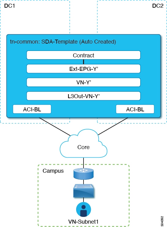
This section describes how to extend an SD-Access (campus) VN to the ACI (data center) fabrics. This action results in the creation of a VRF (and other associated configuration objects that are shown in the following figure representing the mirrored image of the campus VN on the DC side. The created objects are defined in an autogenerated template that is associated to the 'common' tenant.
-
Log in to your Cisco Nexus Dashboard Orchestrator.
-
From the left navigation pane, select Admin > Integrations > DNAC.
-
In the main pane, click the Virtual Networks tab.
A table of Virtual Networks (VNs) appears, displaying all VNs that have been configured by DNAC for IP handoff on the SD-Access border nodes.
-
In the row of the VN to be extended, click the actions menu (…) and select Extend.
A dialog box opens, displaying the ACI sites and interfaces to which the VN will be extended. This information reflects the configuration settings in Configuring Connectivity Toward the Domain.
If you wish to revoke the extending of the VN later, click the actions menu (…) and select Unextend.
-
In the dialog box, click Extend.
The VN is extended to all ACI sites where SD-Access connectivity is enabled, but it is not yet mapped to any ACI VRFs.
Verify the BGP Peering Status of the ACI border leaf switch interfaces:
-
If the SD-Access border nodes and the ACI border leafs are connected directly (back-to-back), verify that, because of extending the campus VN, BGP sessions have been established between these devices. In Admin > Integrations > DNAC > Virtual Networks, click the DC Sites number to open a sidebar that displays details of the ACI border leaf switch interfaces. Check that the BGP Peering Status of the border leaf switch interfaces indicates Up.
-
If an IPN is deployed between the domains, retrieve the configuration samples to help with configuring the next-hop devices that are directly connected to the SD-Access border nodes and to the ACI border leafs. In Admin > Integrations > DNAC > Virtual Networks, click the DC Sites number to open a sidebar that displays details of the ACI border leaf switch interfaces. For IPN-connected border leaf switch interfaces, click the "Show Details" link next to Peering Device Configuration to display a sample IPN device configuration. After configuring the IPN devices, check that the BGP Peering Status of the border leaf switch interfaces indicates Up.
Map the extended VN to one or more ACI VRFs, as described in Mapping or Unmapping a VN to a VRF.
Mapping or Unmapping a VN to a VRF
You must have extended the VN into the ACI site.
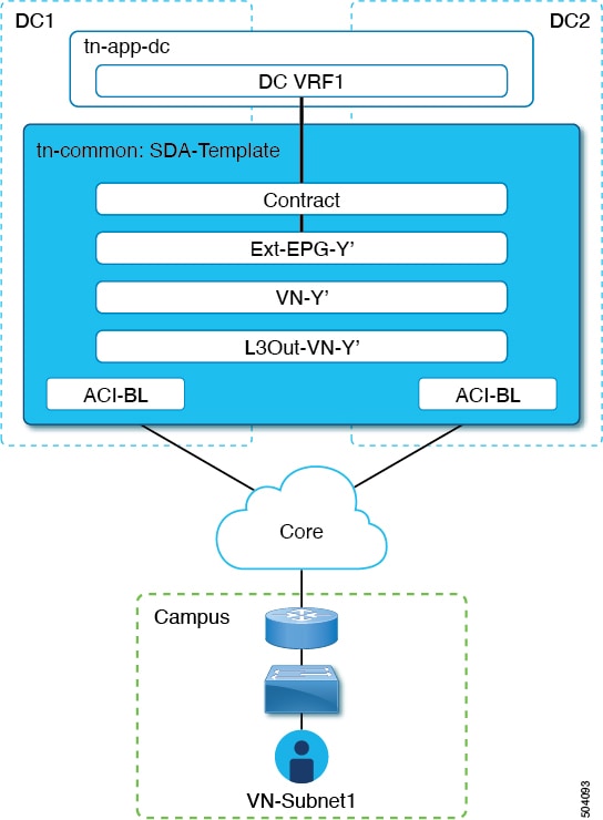
This section describes how to map ("stitch") a virtual network (VN) to one or more data center (DC) VRFs in the ACI fabric. The mapping to a VRF results in the establishment of a contract relationship between the DC VRF (represented by the "vzAny" object) and the external EPG previously provisioned in the 'common' tenant, as shown in the following figure:
-
Log in to your Nexus Dashboard Orchestrator.
-
From the left navigation pane, select Admin > Integrations > DNAC.
-
In the main pane, click the Virtual Networks tab.
A table of Virtual Networks (VNs) appears, displaying all VNs that have been configured by DNAC for IP handoff on the SD-Access border nodes.
-
In the row of the VN to be mapped, click the actions menu (…) and select Map/Un-Map DC VRFs.
A Map/Un-Map DC VRFs dialog box opens.
-
In the Map/Un-Map DC VRFs dialog box, click the + icon next to Add Mapped DC VRF.
-
From the drop-down list of VRFs, choose a VRF.
The selected VRF is added to a table that also displays the template for the VRF. Note the template name, as it will be needed in a later step.
If you wish to map the VN to additional VRFs, click the + icon again to choose additional VRFs from the drop-down list.
You can also un-map a DC VRF by deleting the existing mapping. To un-map a DC VRF, click the trash icon in the row of the VRF.
-
Click Save and wait until the VN Status has changed to 'Success'.
At this point, even if the VN Status indicates 'Success', data connectivity is not yet established between the extended VN and the DC VRF. The mapping operation has modified a template that is associated with the mapped VRF, and you must redeploy the template before connectivity is established. In the Associated Templates table under the VN table, the template that is associated with the mapped VRF appears.
-
In the Associated Templates table in the Admin > Integrations > DNAC > Virtual Networks tab, click the link of the template that is associated with the mapped VRF.
The schema and template page opens.
-
In the schema and template page, click Deploy to sites.
-
If template review and approval (change control) are enabled, follow the change control workflow to redeploy the template. Otherwise, click Deploy to redeploy the template.
Configuring Transit Routing
You must have mapped an extended campus VN to a data center VRF and established connectivity.
When an extended SD-Access (campus) VN is mapped to an ACI (data center) VRF, any BD subnets of the DC VRF that are configured with "Advertised Externally" and "Shared between VRFs" flags are leaked into the 'common' tenant VRF and then advertised toward the SD-Access domain. This ensures that campus users can gain access to the applications provisioned in the DC VRF.
When an SD-Access VN is mapped to multiple ACI VRFs, only nonoverlapping prefixes across all mapped ACI VRFs should be configured as "shared between VRFs".
In addition to the advertisement of those BD subnets, there may be a requirement for campus users to access an external L3 network domain using the ACI domain as transit.
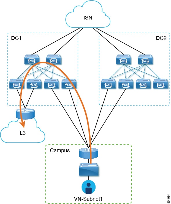
In this scenario, an L3Out connection that is associated to the DC VRF (L3Out-DC-VRF) is provisioned for allowing connectivity to the external domain and external routes (a simple 0.0.0.0/0 default in the following example are imported in the DC VRF routing table (part of tn-app-dc).
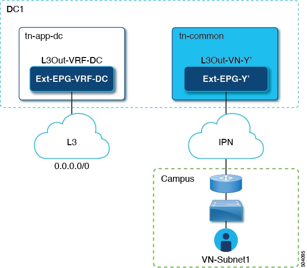
To ensure that campus users can connect to the external L3 domain through the data center, the external routes must be leaked to the uncommon VRF so that they can be advertised toward the campus domain through the L3Out connection (L3Out-VN-Y') autogenerated because of the campus VN extension to the DC.
Follow this procedure to enable leaking of the external routes:
-
Log in to your Cisco Nexus Dashboard Orchestrator.
-
From the left navigation pane, select Admin > Integrations > DNAC.
-
In the main pane, click the Virtual Networks tab.
-
In the row of a successfully mapped campus VN, click the actions menu (…) and select Enable Transit Route.
This configuration creates a 0.0.0.0/0 prefix under Ext-EPG-Y', with the following "Route Control" flags set that allows the advertising toward the IPN of all external routes leaked from the tn-app-dc tenant.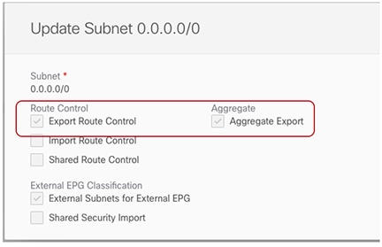 Figure 6. Export Route Control
To disable transit routing, click the actions menu (…) and select Disable Transit Route.
With either setting (enabled or disabled), the campus site has access to shared BD subnets internal to the ACI VRF.
-
From the left navigation pane, choose Configure > Tenanat Template > Applications > Schemas and navigate to the template for configuring the data center tenant application.
-
In the data center tenant application template, configure the flags under the 0.0.0.0/0 prefix that is associated to Ext-EPG-VRF-DC of the DC VRF to be able to leak into uncommon the external routes learned from the Internet.
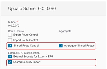
The setting that is shown ensures that all the external prefixes that are received on L3Out-VRF-DC are leaked to tm-common and are therefore advertised toward the campus domain. This setting also allows leaking of the 0.0.0.0/0 default route if it is received from the L3 domain. If needed, you can apply a more granular configuration where only a subset of the external prefixes can be leaked to uncommon. This is achieved by creating specific entries matching those subsets of prefixes and applying to those entries the same flag configuration shown here.
-
In the data center tenant application template, define a specific prefix under Ext-EPG-VRF-DC matching the campus VN subnet (or set of subnets) to be advertised toward the external L3 domain.
In the example shown in the following figure, this configuration is applied to a specific 192.168.100.0/24 prefix.
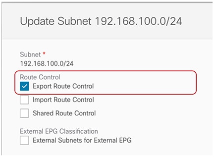 Figure 7. Update Subnet
Creating a separate prefix for a VN subnet provides the most granular level of control for the advertisement of campus VN subnets toward the external L3 domain. If such granular control is not needed, you can set the "Export Route Control" flags associated to the 0.0.0.0/0 prefix instead, which allows sending toward the external domain all the campus VN subnets that have been leaked into tn-app-dc from uncommon.
First Published: 2024-03-01
Last Modified: 2024-03-01
Americas Headquarters
Cisco Systems, Inc.
170 West Tasman Drive
San Jose, CA 95134-1706
USA
http://www.cisco.com
Tel: 408 526-4000
800 553-NETS (6387)
Fax: 408 527-0883