- About this Guide
- Cisco Service Control Overview
- System Overview
- Traffic Processing Overview
- Getting Started
- Using the Network Navigator
- Using the Service Configuration Editor
- Using the Service Configuration Editor: Traffic Classification
- Using the Service Configuration Editor: Traffic Accounting and Reporting
- Using the Service Configuration Editor: Traffic Control
- Using the Service Configuration Editor: Additional Options
- Using the Subscriber Manager GUI Tool
- Using the Anonymous Group Manager Tool
- Using the Signature Editor
- Additional Management Tools and Interfaces
Cisco Service Control Application for Broadband User Guide, Release 4.1.x
Bias-Free Language
The documentation set for this product strives to use bias-free language. For the purposes of this documentation set, bias-free is defined as language that does not imply discrimination based on age, disability, gender, racial identity, ethnic identity, sexual orientation, socioeconomic status, and intersectionality. Exceptions may be present in the documentation due to language that is hardcoded in the user interfaces of the product software, language used based on RFP documentation, or language that is used by a referenced third-party product. Learn more about how Cisco is using Inclusive Language.
- Updated:
- February 23, 2012
Chapter: Using the Service Configuration Editor: Traffic Classification
- Introduction
- How to Search Traffic Classification Settings
- Managing Services
- How to Add Zone Items
- How to Edit Zone Items
- How to Delete Zone Items
- BGP AS Dynamic Detection Workflow
- Enabling BGP AS Dynamic Detection
- Collecting and Storing the BGP Autonomous System (AS) Details
- Creating a New Zone with Select BGP AS Numbers and Prefixes
- Understanding BGP AS Numbers and Prefixes Color Schema
- Updating a Zone with Select BGP AS Numbers and Prefixes
- Deleting IP Prefixes from a Zone
Using the Service Configuration Editor: Traffic Classification
Introduction
Traffic classification is the first step in creating a Cisco SCA BB service configuration. Traffic is classified according to services.
For each commercial service that providers offer to their subscribers, a corresponding service is defined in the Cisco Service Control solution. You can use this service to classify and identify the traffic, report on its usage, and control it.
This module explains how to work with services and their elements and subelements:
•![]() How to Search Traffic Classification Settings
How to Search Traffic Classification Settings
How to Search Traffic Classification Settings
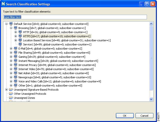
You can search for any classification detail by name or numeric ID, such as services, protocols, port number, or counter assignments. You can also search for protocols or signatures that are not assigned to a service.
Step 1 ![]() In the Classification tab, click the Search Classification Settings (
In the Classification tab, click the Search Classification Settings ( ) icon.
The Search Classification Settings dialog box appears (Figure 7-1).
Figure 7-1 Search Classification Settings
Step 2 ![]() Enter the text to search.
Enter the text to search.

Note ![]() You can include the following wildcards in the search:
You can include the following wildcards in the search:
•![]() ?—any character
?—any character
•![]() · *—any string
· *—any string
The dialog box is populated with the search results.
Step 3 ![]() Double-click the item to take you to the screen where you can edit it. For example, if you double-click a protocol, the protocol dialog box opens on the selected protocol.
Double-click the item to take you to the screen where you can edit it. For example, if you double-click a protocol, the protocol dialog box opens on the selected protocol.
Managing Services
Services are used to classify controlled traffic.
A service consists of one or more service elements; different network traffic transaction types are mapped to different service elements.
Traffic is classified based on some or all of the following:
•![]() Protocol—The protocol used by the transaction, as identified by the Cisco Service Control Engine (Cisco SCE) platform
Protocol—The protocol used by the transaction, as identified by the Cisco Service Control Engine (Cisco SCE) platform
•![]() Initiating side—Where the transaction was initiated
Initiating side—Where the transaction was initiated
•![]() Zone—IP address of the network-side host of the transaction
Zone—IP address of the network-side host of the transaction
•![]() Flavor—Specific Layer 7 properties of the transaction; for example, host names of the network-side host of the transaction
Flavor—Specific Layer 7 properties of the transaction; for example, host names of the network-side host of the transaction
A service configuration can contain up to 500 services and 10,000 service elements. Every service element in a service configuration must be unique.
Service Parameters
A service is defined by the following parameters:
•![]() General parameters:
General parameters:
–![]() Name—A unique name
Name—A unique name
–![]() Description—(Optional) A description of the service
Description—(Optional) A description of the service
•![]() Hierarchy parameters:
Hierarchy parameters:
–![]() Parent Service
Parent Service
The default service, which is the base of the service hierarchy, does not have a parent.
Note ![]() The parent service is important when services share usage counters (see next parameter).
The parent service is important when services share usage counters (see next parameter).
–![]() Service Usage Counters—Used by the system to generate data about the total use of each service. A service can use either its own usage counters, or those of the parent service.
Service Usage Counters—Used by the system to generate data about the total use of each service. A service can use either its own usage counters, or those of the parent service.
Each usage counter has:
–![]() A name assigned by the system (based on the service name).
A name assigned by the system (based on the service name).
Note ![]() An asterisk is appended to a service usage counter name whenever the counter applies to more than one service.
An asterisk is appended to a service usage counter name whenever the counter applies to more than one service.
–![]() A unique counter index—A default value of the counter index provided by the system. Do not modify this value.
A unique counter index—A default value of the counter index provided by the system. Do not modify this value.
•![]() Advanced parameter:
Advanced parameter:
–![]() Service Index—A unique number by which the system recognizes the service (changing the service name does not affect Cisco SCE platform activity). The system provides a default value of the service index. Do not modify this value.
Service Index—A unique number by which the system recognizes the service (changing the service name does not affect Cisco SCE platform activity). The system provides a default value of the service index. Do not modify this value.
These parameters are defined when you add a new service (see "How to Add a Service to a Service Configuration" section). You can modify them at any time (see "How to Edit Services" section).
Adding and Defining Services
A number of services are predefined in the Console installation. You can add additional services to a service configuration, subject to the limit of 500 services (including predefined services) per service configuration.
After you have added and defined a new service, you can add service elements to the service (see "How to Add Service Elements" section).
•![]() How to Add a Service to a Service Configuration
How to Add a Service to a Service Configuration
•![]() How to Define Hierarchical Settings for a Service
How to Define Hierarchical Settings for a Service
How to Add a Service to a Service Configuration
Step 1 ![]() In the Services tab, select a service from the service tree. This service is the parent of the service you are adding.
In the Services tab, select a service from the service tree. This service is the parent of the service you are adding.
Step 2 ![]() In the left pane, click the Add Service (
In the left pane, click the Add Service ( ) icon.
The Service Settings dialog box appears (Figure 7-2).
Figure 7-2 Service Settings
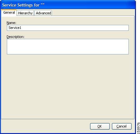
Step 3 ![]() In the Name field, enter a unique and relevant name for the service.
In the Name field, enter a unique and relevant name for the service.
Step 4 ![]() In the Description field, enter a meaningful and useful description of the service.
In the Description field, enter a meaningful and useful description of the service.
Step 5 ![]() To set exclusive usage counters for this service, or to change the parent service you selected when adding the service, continue with the instructions in the "How to Define Hierarchical Settings for a Service" section section.
To set exclusive usage counters for this service, or to change the parent service you selected when adding the service, continue with the instructions in the "How to Define Hierarchical Settings for a Service" section section.
Step 6 ![]() (Optional) To specify an index for this service, continue with the instructions in the "How to Set the Service Index" section section.
(Optional) To specify an index for this service, continue with the instructions in the "How to Set the Service Index" section section.
Note ![]() The system automatically assigns a free number for the new service. Modify this number only where a specific index value must be assigned to a specific service.
The system automatically assigns a free number for the new service. Modify this number only where a specific index value must be assigned to a specific service.
Step 7 ![]() Click OK.
Click OK.
The Service Settings dialog box closes.
The service is added to the service tree as a child to the service you selected in the hierarchy.
How to Define Hierarchical Settings for a Service
Step 1 ![]() In the Service Settings dialog box, click the Hierarchy tab.
In the Service Settings dialog box, click the Hierarchy tab.
The Hierarchy tab opens (Figure 7-3).
Figure 7-3 Hierarchy Tab
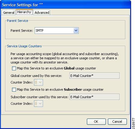
Step 2 ![]() To set a different parent service, select the desired parent from the Parent Service drop-down list.
To set a different parent service, select the desired parent from the Parent Service drop-down list.
Step 3 ![]() By default, a new service uses the global usage counter of its parent service. To define an exclusive global usage counter, check the Map this Service to an exclusive Global usage counter check box.
By default, a new service uses the global usage counter of its parent service. To define an exclusive global usage counter, check the Map this Service to an exclusive Global usage counter check box.
The name in the read-only Global counter of this service field changes to reflect your choice.
The Counter Index drop-down list is enabled.
(Optional) Select a value for the counter index from the Counter Index drop-down list. Effective with Cisco SCE Release 4.0.0, you can select upto 192 counter index values.
Note ![]() The system provides a default value of the counter index. Do not modify this value.
The system provides a default value of the counter index. Do not modify this value.
Step 4 ![]() By default, a new service uses the subscriber usage counter of its parent service. To define an exclusive subscriber usage counter, check the Map this Service to an exclusive Subscriber usage counter check box.
By default, a new service uses the subscriber usage counter of its parent service. To define an exclusive subscriber usage counter, check the Map this Service to an exclusive Subscriber usage counter check box.
The name in the read-only Subscriber counter of this service field changes to reflect your choice.
The Counter Index drop-down list is enabled.
(Optional) Select a value for the counter index from the Counter Index drop-down list. Effective with Cisco SCE Release 4.0.0, you can select upto 48 counter index values.
Note ![]() The system provides a default value of the counter index. Do not modify this value.
The system provides a default value of the counter index. Do not modify this value.
Step 5 ![]() To specify an index for this service, continue with the instructions in the "How to Set the Service Index" section section.
To specify an index for this service, continue with the instructions in the "How to Set the Service Index" section section.
Note ![]() The system automatically assigns a free number for the new service. Modify this number only where a specific index value must be assigned to a specific service.
The system automatically assigns a free number for the new service. Modify this number only where a specific index value must be assigned to a specific service.
Step 6 ![]() Click OK.
Click OK.
The Service Settings dialog box closes.
The service is added to the service tree as a child to the service selected in the Parent Service drop-down list.
How to Set the Service Index
Step 1 ![]() In the Service Settings dialog box, click the Advanced tab.
In the Service Settings dialog box, click the Advanced tab.
The Advanced tab opens (Figure 7-4).
Figure 7-4 Advanced Tab
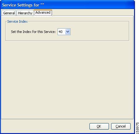
Step 2 ![]() From the Set the Index for this Service drop-down list, select a service index.
From the Set the Index for this Service drop-down list, select a service index.
The service index must be an integer in the range from 1 to 499; zero is reserved for the default service.
Note ![]() The system automatically assigns a free number for the new service. Modify this number only where a specific index value must be assigned to a specific service.
The system automatically assigns a free number for the new service. Modify this number only where a specific index value must be assigned to a specific service.
Step 3 ![]() Click OK.
Click OK.
The Service Settings dialog box closes.
The service is added to the service tree as a child to the service selected in the Parent Service drop-down list.
How to View Services
You can view a hierarchy tree of all existing services and see their associated service elements.
Step 1 ![]() In the current service configuration, click the Classification tab.
In the current service configuration, click the Classification tab.
The Classification tab appears (Figure 7-5).
Figure 7-5 Classification Tab
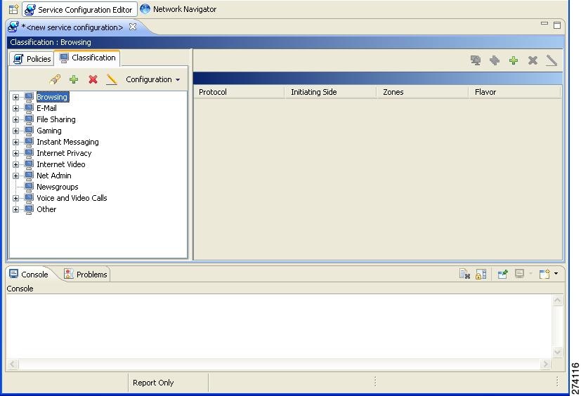
A list of all services is displayed in the service tree (left pane).
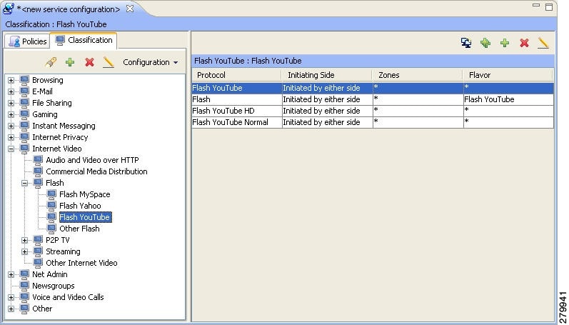
Step 2 ![]() Click a service in the hierarchy to display its service elements.
Click a service in the hierarchy to display its service elements.
A list of all service elements defined for this service is displayed in the right (Service Elements) pane (Figure 7-6).
Figure 7-6 Service Elements
Step 3 ![]() To view more information about a service, select a service from the service tree and click the Edit Service (
To view more information about a service, select a service from the service tree and click the Edit Service ( ) icon.
The Service Settings dialog box appears.
Step 4 ![]() Click OK.
Click OK.
The Service Settings dialog box closes.
How to Edit Services
You can modify the parameters of a service, even those parameters included in the Console installation.
To add, modify, or delete service elements, see "Managing Service Elements" section.
Step 1 ![]() In the Services tab, select a service from the service tree.
In the Services tab, select a service from the service tree.
Step 2 ![]() In the left pane, click the Edit Service () icon.
In the left pane, click the Edit Service () icon.
The Service Settings dialog box appears.
Step 3 ![]() (Optional) Give a new name to the service.
(Optional) Give a new name to the service.
Enter a new name in the Name field.
Step 4 ![]() (Optional) Give a new description for the service.
(Optional) Give a new description for the service.
Enter a new description in the Description field.
Step 5 ![]() To change hierarchical settings, click the Hierarchy tab.
To change hierarchical settings, click the Hierarchy tab.
The Hierarchy tab opens.
a. ![]() To set a different parent service, select the desired service from the Parent Service drop-down list.
To set a different parent service, select the desired service from the Parent Service drop-down list.
b. ![]() To share a global usage counter with the parent service, uncheck the Map this Service to an exclusive Global usage counter check box.
To share a global usage counter with the parent service, uncheck the Map this Service to an exclusive Global usage counter check box.
The name of the parent service's counter is displayed in the Global counter used by this service field.
c. ![]() To define an exclusive global usage counter, check the Map this Service to an exclusive Global usage counter check box.
To define an exclusive global usage counter, check the Map this Service to an exclusive Global usage counter check box.
The name in the read-only Global counter of this service field changes to reflect your choice.
The Counter Index drop-down list is enabled.
Note ![]() The system provides a default value of the counter index. Do not modify this value.
The system provides a default value of the counter index. Do not modify this value.
d. ![]() To share a subscriber usage counter with the parent service, uncheck the Map this Service to an exclusive Subscriber usage counter check box.
To share a subscriber usage counter with the parent service, uncheck the Map this Service to an exclusive Subscriber usage counter check box.
The name of the parent service's counter is displayed in the Subscriber counter used by this service field.
e. ![]() To define an exclusive subscriber usage counter, check the Map this Service to an exclusive Subscriber usage counter check box.
To define an exclusive subscriber usage counter, check the Map this Service to an exclusive Subscriber usage counter check box.
The name in the read-only Subscriber counter of this service field changes to reflect your choice.
The Counter Index drop-down list is enabled.
Note ![]() The system provides a default value of the counter index. Do not modify this value.
The system provides a default value of the counter index. Do not modify this value.
Step 6 ![]() To change the service index:
To change the service index:
a. ![]() In the Service Settings dialog box, click the Advanced tab.
In the Service Settings dialog box, click the Advanced tab.
The Advanced tab opens.
b. ![]() From the Set the Index for this Service drop-down list, select a service index.
From the Set the Index for this Service drop-down list, select a service index.
The service index must an integer in the range from 1 to 499; zero is reserved for the default service.
Note ![]() The system provides a default value of the service index. Do not modify this value.
The system provides a default value of the service index. Do not modify this value.
Step 7 ![]() Click OK.
Click OK.
The Service Settings dialog box closes.
The changes to the service are saved.
How to Delete Services
You can delete all services, even those services in the Console installation, except for the default service.
Step 1 ![]() In the Services tab, select a service from the service tree.
In the Services tab, select a service from the service tree.
Step 2 ![]() In the left pane, click the Delete Service (
In the left pane, click the Delete Service ( ) icon.
Step 3 ![]() A Service Warning message appears (Figure 7-7).
A Service Warning message appears (Figure 7-7).
Figure 7-7 Service Warning
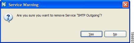
Step 4 ![]() Click Yes.
Click Yes.
•![]() If any package has a rule for this service (see "Managing Rules" section), a second Service Warning message appears (Figure 7-8).
If any package has a rule for this service (see "Managing Rules" section), a second Service Warning message appears (Figure 7-8).
Figure 7-8 Service Warning
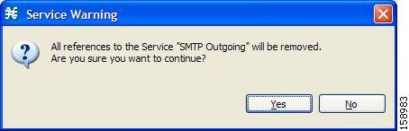
•![]() Click Yes.
Click Yes.
The service is deleted and is no longer displayed in the service tree. Any rules for the service are also deleted.
Children of the deleted service are not deleted; they move up one level in the service tree.
Managing Service Elements
A service is a collection of service elements; to complete the definition of a service, you must define its service elements. A service element maps a specific protocol, initiating side, zone, and flavor to the selected service.
For more information, see "Managing Protocols" section, "Managing Zones" section, and "Managing Flavors" section.
A service configuration can contain up to 10,000 service elements. Every service element must be unique.
A service element maps a traffic flow, that meets all the following criteria, to its service:
•![]() The flow uses the specified protocol of the service element.
The flow uses the specified protocol of the service element.
•![]() The flow is initiated by the side (network, subscriber, or either) specified for the service element.
The flow is initiated by the side (network, subscriber, or either) specified for the service element.
•![]() The destination of the flow is an address that belongs to the specified zone of the service element.
The destination of the flow is an address that belongs to the specified zone of the service element.
•![]() The flow matches the specified flavor of the service element.
The flow matches the specified flavor of the service element.
•![]() The service element is the most specific service element satisfying the first four criteria.
The service element is the most specific service element satisfying the first four criteria.
How to Add Service Elements
When necessary, you can add new service elements to a service. (The most useful service elements are included in the Console installation.) A service may have any number of service elements (subject to the limit of 10,000 service elements per service configuration).
Note ![]() Every service element must be unique. If, at any stage, the new service element is the same as an existing one, an error message is displayed in the dialog box, and the Finish button is dimmed. To proceed, modify the value in at least one field.
Every service element must be unique. If, at any stage, the new service element is the same as an existing one, an error message is displayed in the dialog box, and the Finish button is dimmed. To proceed, modify the value in at least one field.
Step 1 ![]() In the Services tab, select a service from the service tree.
In the Services tab, select a service from the service tree.
Step 2 ![]() In the right (Service Elements) pane, click the Add Service Element ().
In the right (Service Elements) pane, click the Add Service Element ().
The New Service Element dialog box appears (Figure 7-9).
Figure 7-9 New Service Element
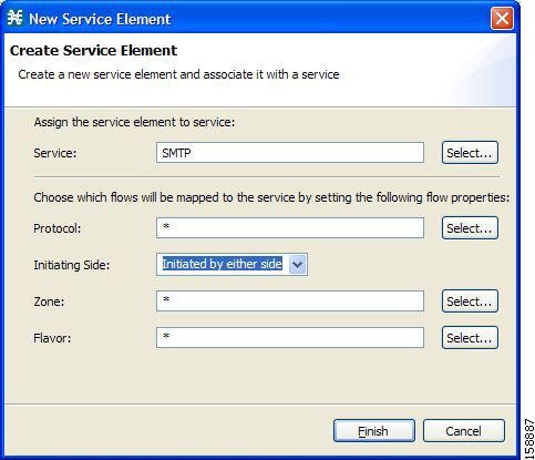
Step 3 ![]() To change the service to which this service element is assigned, click the Select button next to the Service field.
To change the service to which this service element is assigned, click the Select button next to the Service field.
The Select a Service dialog box appears (Figure 7-10), displaying a list of all services.
Figure 7-10 Select a Service
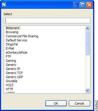
Step 4 ![]() Select a service from the list.
Select a service from the list.
Step 5 ![]() Click OK.
Click OK.
The Select a Service dialog box closes.
The selected service is displayed in the Service field of the New Service Element dialog box.
Step 6 ![]() Click the Select button next to the Protocol field.
Click the Select button next to the Protocol field.
Note ![]() The default value (an asterisk, *) means that no protocol checking is performed when testing whether a flow maps to this service element.
The default value (an asterisk, *) means that no protocol checking is performed when testing whether a flow maps to this service element.
The Select a Protocol dialog box appears (Figure 7-11), displaying a list of all protocols.
Note ![]() If you select a flavor (Step 15) before you select a protocol, only protocols relevant to the selected flavor are displayed.
If you select a flavor (Step 15) before you select a protocol, only protocols relevant to the selected flavor are displayed.
Figure 7-11 Select a Protocol
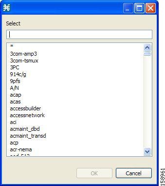
Step 7 ![]() Select a protocol from the list. You can type in the field at the top of the dialog box to help locate the desired protocol.
Select a protocol from the list. You can type in the field at the top of the dialog box to help locate the desired protocol.
Step 8 ![]() Click OK.
Click OK.
The Select a Protocol dialog box closes.
The selected protocol is displayed in the Protocol field of the New Service Element dialog box.
Step 9 ![]() In the Initiating Side field (Figure 7-12), click the drop-down arrow.
In the Initiating Side field (Figure 7-12), click the drop-down arrow.
Figure 7-12 Initiating Side Field
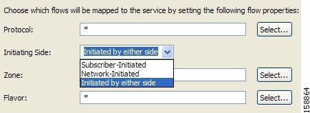
Step 10 ![]() Select the appropriate initiating side from the drop-down list.
Select the appropriate initiating side from the drop-down list.
The following options are available:
•![]() Subscriber-Initiated—Transactions are initiated at the subscriber side towards (a server at) the network side.
Subscriber-Initiated—Transactions are initiated at the subscriber side towards (a server at) the network side.
•![]() Network-Initiated—Transactions are initiated at the network side towards (a server at) the subscriber side.
Network-Initiated—Transactions are initiated at the network side towards (a server at) the subscriber side.
•![]() Initiated by either side
Initiated by either side
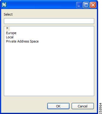
Step 11 ![]() Click the Select button next to the Zone field.
Click the Select button next to the Zone field.
Note ![]() The default value (an asterisk, *) means that no zone checking is performed when testing whether a flow maps to this service element.
The default value (an asterisk, *) means that no zone checking is performed when testing whether a flow maps to this service element.
The Select a Zone dialog box appears (Figure 7-13), displaying a list of all zones.
Figure 7-13 Select a Zone
Step 12 ![]() Select a zone from the list.
Select a zone from the list.
Step 13 ![]() Click OK.
Click OK.
The Select a Zone dialog box closes.
The selected zone is displayed in the Zone field of the New Service Element dialog box.
Note ![]() If you select a zone in which data flows are classified using zones only, the Protocol, Initiating Side, and Flavor fields are disabled.
If you select a zone in which data flows are classified using zones only, the Protocol, Initiating Side, and Flavor fields are disabled.
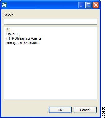
Step 14 ![]() Click the Select button next to the Flavor field.
Click the Select button next to the Flavor field.
Note ![]() The default value (an asterisk, *) means that no flavor checking is performed when testing whether a flow maps to this service element.
The default value (an asterisk, *) means that no flavor checking is performed when testing whether a flow maps to this service element.
The Select a Flavor dialog box appears (Figure 7-14), displaying a list of all flavors relevant to the protocol selected in Step 7.
Note ![]() You can only select a ToS flavor if you select the default value (*, meaning any protocol) for the protocol.
You can only select a ToS flavor if you select the default value (*, meaning any protocol) for the protocol.
Figure 7-14 Select a Flavor
Step 15 ![]() Select a flavor from the list.
Select a flavor from the list.
Step 16 ![]() Click OK.
Click OK.
The Select a Flavor dialog box closes.
The selected flavor is displayed in the Flavor field of the New Service Element dialog box.
Step 17 ![]() Click Finish.
Click Finish.
The New Service Element dialog box closes.
The new service element is added to the service.
A new row, representing the service element, is added to the service element list in the Service Elements pane.
How to Duplicate Service Elements
Duplicating an existing service element is a useful way to add a new service element similar to an existing service element. It is faster to duplicate a service element and then modify it than to define the service element from beginning.
Note ![]() Every service element must be unique. If, at any stage, the new service element is the same as an existing one, an error message is displayed in the dialog box, and the Finish button is dimmed. To proceed, modify the value in at least one field.
Every service element must be unique. If, at any stage, the new service element is the same as an existing one, an error message is displayed in the dialog box, and the Finish button is dimmed. To proceed, modify the value in at least one field.
Step 1 ![]() In the Services tab, select a service from the service tree.
In the Services tab, select a service from the service tree.
A list of associated service elements is displayed in the Service Elements pane.
Step 2 ![]() In the Service Elements pane, select a service element to duplicate.
In the Service Elements pane, select a service element to duplicate.
Step 3 ![]() Click the Duplicate Service Element (
Click the Duplicate Service Element ( ) icon.
The Copy Service Element dialog box appears (Figure 7-15).
Figure 7-15 Copy Service Element
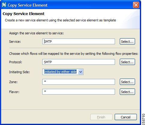
Step 4 ![]() Modify the service element (see "How to Edit Service Elements" section).
Modify the service element (see "How to Edit Service Elements" section).
Note ![]() Before you can save the new service element, you must change the value in at least one field.
Before you can save the new service element, you must change the value in at least one field.
How to Edit Service Elements
You can modify all service elements, even those service elements that are included in the Console installation.
Note ![]() Every service element must be unique. If, at any stage, the modified service element is the same as an existing one, an error message is displayed in the dialog box, and the Finish button is dimmed. To proceed, modify the value in at least one field.
Every service element must be unique. If, at any stage, the modified service element is the same as an existing one, an error message is displayed in the dialog box, and the Finish button is dimmed. To proceed, modify the value in at least one field.
Step 1 ![]() In the Services tab, select a service from the service tree.
In the Services tab, select a service from the service tree.
A list of associated service elements is displayed in the Service Elements pane.
Step 2 ![]() In the Service Elements pane, select a service element to edit.
In the Service Elements pane, select a service element to edit.
Step 3 ![]() In the Service Elements pane, click the Edit Service Element () icon.
In the Service Elements pane, click the Edit Service Element () icon.
The Edit Service Element dialog box appears (Figure 7-16).
Figure 7-16 Edit Service Element
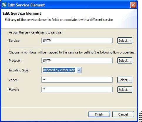
Step 4 ![]() To change the service to which this service element is assigned, click the Select button next to the Service field.
To change the service to which this service element is assigned, click the Select button next to the Service field.
The Select a Service dialog box appears, displaying a list of all services.
Step 5 ![]() Select a service from the list.
Select a service from the list.
Step 6 ![]() Click OK.
Click OK.
The Select a Service dialog box closes.
The selected service is displayed in the Service field of the Edit Service Element dialog box.
Step 7 ![]() To change the protocol of this service element, click the Select button next to the Protocol field.
To change the protocol of this service element, click the Select button next to the Protocol field.
Note ![]() An asterisk (*) means that no protocol checking is performed when testing whether a flow maps to this service element.
An asterisk (*) means that no protocol checking is performed when testing whether a flow maps to this service element.
The Select a Protocol dialog box appears, displaying a list of all protocols.
Step 8 ![]() Select a protocol from the list; you can type in the field at the top of the dialog box to help locate the desired protocol.
Select a protocol from the list; you can type in the field at the top of the dialog box to help locate the desired protocol.
Step 9 ![]() Click OK.
Click OK.
The Select a Protocol dialog box closes.
The selected protocol is displayed in the Protocol field of the Edit Service Element dialog box.
Step 10 ![]() To change the initiating side of this service element, click the drop-down arrow in the Initiating Side field.
To change the initiating side of this service element, click the drop-down arrow in the Initiating Side field.
Step 11 ![]() Select the appropriate initiating side from the drop-down list.
Select the appropriate initiating side from the drop-down list.
The following options are available:
•![]() Subscriber-Initiated—Transactions are initiated at the subscriber side towards (a server at) the network side.
Subscriber-Initiated—Transactions are initiated at the subscriber side towards (a server at) the network side.
•![]() Network-Initiated—Transactions are initiated at the network side towards (a server at) the subscriber side.
Network-Initiated—Transactions are initiated at the network side towards (a server at) the subscriber side.
•![]() Initiated by either side
Initiated by either side
Step 12 ![]() To change the zone of this service element, click the Select button next to the Zone field.
To change the zone of this service element, click the Select button next to the Zone field.
Note ![]() An asterisk (*) means that no zone checking is performed when testing whether a flow maps to this service element.
An asterisk (*) means that no zone checking is performed when testing whether a flow maps to this service element.
The Select a Zone dialog box appears, displaying a list of all zones.
Step 13 ![]() Select a zone from the list.
Select a zone from the list.
Step 14 ![]() Click OK.
Click OK.
The Select a Zone dialog box closes.
The selected zone is displayed in the Zone field of the Edit Service Element dialog box.
Step 15 ![]() To change the flavor of this service element, click the Select button next to the Flavor field.
To change the flavor of this service element, click the Select button next to the Flavor field.
Note ![]() An asterisk (*) means that no flavor checking is performed when testing whether a flow maps to this service element.
An asterisk (*) means that no flavor checking is performed when testing whether a flow maps to this service element.
The Select a Flavor dialog box appears, displaying a list of all flavors.
Step 16 ![]() Select a flavor from the list.
Select a flavor from the list.
Step 17 ![]() Click OK.
Click OK.
The Select a Flavor dialog box closes.
The selected flavor is displayed in the Flavor field of the Edit Service Element dialog box.
Step 18 ![]() Click Finish.
Click Finish.
The Edit Service Element dialog box closes.
The changes to the service element are saved.
The changes to the service element appear in the service element list in the Service Elements pane.
How to Delete Service Element
You can delete all service elements, even those service elements that are included in the Console installation.
Step 1 ![]() In the Services tab, select a service from the service tree.
In the Services tab, select a service from the service tree.
A list of associated service elements is displayed in the Service Elements pane.
Step 2 ![]() In the Service Elements pane, select a service element to delete.
In the Service Elements pane, select a service element to delete.
Step 3 ![]() In the Service Elements pane, click the Delete Service Element () icon.
In the Service Elements pane, click the Delete Service Element () icon.
A Service Warning message appears (Figure 7-17).
Figure 7-17 Service Warning

Step 4 ![]() Click Yes.
Click Yes.
The service element is deleted and is no longer part of the selected service.
How to Move Service Elements
You can move an existing service element from one service to a different service.
Step 1 ![]() In the Services tab, select a service from the service tree.
In the Services tab, select a service from the service tree.
A list of associated service elements is displayed in the Service Elements pane.
Step 2 ![]() In the Service Elements pane, select a service element to move.
In the Service Elements pane, select a service element to move.
Step 3 ![]() Click the Move Service Element to Another Service (
Click the Move Service Element to Another Service ( ) icon.
The Move Service Element dialog box appears (Figure 7-18), displaying the complete service tree.
Figure 7-18 Move Service Element
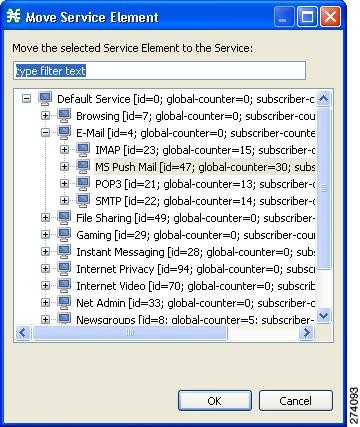
Step 4 ![]() From the service tree, select a service.
From the service tree, select a service.
Step 5 ![]() Click OK.
Click OK.
The Move Service Element dialog box closes.
The service element is moved to the selected service.
Managing Protocols
A protocol is composed of an application protocol signature, the destination port or ports, a unique name, and an optional description.
Protocols are used to define service elements (see the "Managing Service Elements" section).
You can add new protocols (for example, to classify a new gaming protocol that uses a specific port). You can also edit or delete existing ones.
A service configuration can contain up to 10,000 protocols.
Cisco SCA BB supports many commercial and common protocols.
For a complete list of protocols included with the current release of Cisco SCA BB, see the "Information About Protocols" section in the "Default Service Configuration Reference Tables" chapter of Cisco Service Control Application for Broadband Reference Guide.
This section explains the following procedures:
As new protocols are released, Cisco provides files containing the new protocol signatures so that you can add the signatures to your service configuration. See the "How to Import a Dynamic Signature Script into a Service Configuration" section.
Viewing Protocols
This section explains the following procedures:
•![]() How to Filter the Protocols List
How to Filter the Protocols List
How to View Protocols
You can view a list of all protocols and their associated protocol elements.
The protocols are listed in ASCII sort order (that is, 0... 9, A... Z, a... z).
The protocol elements are not sorted; they are listed in the order in which they were added to the protocol.
Step 1 ![]() From the Classification tab in the left pane, choose Configuration > Classification > Protocols.
From the Classification tab in the left pane, choose Configuration > Classification > Protocols.
The Protocol Settings dialog box appears (Figure 7-19).
Figure 7-19 Protocol Settings
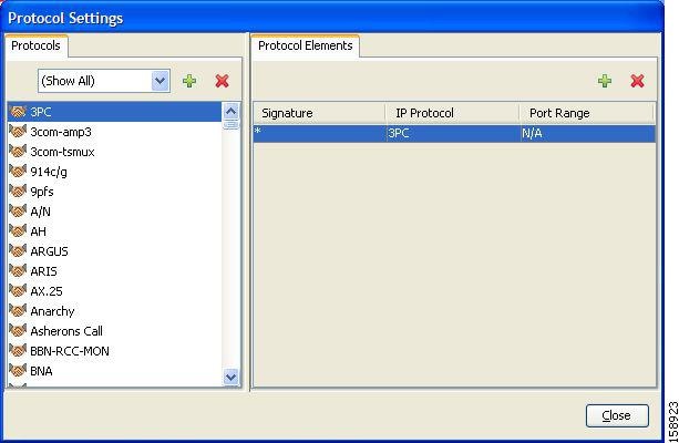
The Protocols tab displays a list of existing protocols.
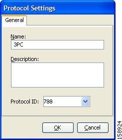
Step 2 ![]() Double-click a protocol to view its description and ID.
Double-click a protocol to view its description and ID.
The Protocol Settings dialog box appears (Figure 7-20), displaying the protocol name, description, and ID.
Figure 7-20 Protocol Settings
Step 3 ![]() Click Cancel.
Click Cancel.
The Protocol Settings dialog box closes.
Step 4 ![]() To view a list of protocol elements, select a protocol in the list in the Protocol Settings dialog box.
To view a list of protocol elements, select a protocol in the list in the Protocol Settings dialog box.
Protocol elements are displayed in the Protocol Elements tab.
Step 5 ![]() Click Close.
Click Close.
The Protocol Settings dialog box closes.
How to Filter the Protocols List
You can filter the protocols by type, so that the Protocols tab displays only the selected type of protocol.
The categories of protocols include:
•![]() Generic Protocols—Generic IP, Generic TCP, and Generic UDP protocols, used for transactions that are not specifically mapped to a protocol by any other protocol type.
Generic Protocols—Generic IP, Generic TCP, and Generic UDP protocols, used for transactions that are not specifically mapped to a protocol by any other protocol type.
•![]() IP Protocols—Protocols (such as ICMP), other than TCP and UDP protocols, identified according to the IP protocol number of the transaction.
IP Protocols—Protocols (such as ICMP), other than TCP and UDP protocols, identified according to the IP protocol number of the transaction.
•![]() Port-Based Protocols—TCP and UDP protocols, classified according to their well-known ports. The default service configuration includes more than 750 common port-based protocols.
Port-Based Protocols—TCP and UDP protocols, classified according to their well-known ports. The default service configuration includes more than 750 common port-based protocols.
•![]() Signature-Based Protocols—Protocols classified according to a Layer 7 application signature. Includes the most common protocols, such as HTTP and FTP, and a large group of popular P2P protocols.
Signature-Based Protocols—Protocols classified according to a Layer 7 application signature. Includes the most common protocols, such as HTTP and FTP, and a large group of popular P2P protocols.
•![]() P2P Protocols—Peer-to-peer file-sharing application protocols, classified according to a Layer 7 application signature.
P2P Protocols—Peer-to-peer file-sharing application protocols, classified according to a Layer 7 application signature.
•![]() VoIP Protocols—Voice-over-IP application protocols, classified according to a Layer 7 application signature.
VoIP Protocols—Voice-over-IP application protocols, classified according to a Layer 7 application signature.
•![]() SIP Protocols—Protocols classified according to a Layer 7 application signature that is SIP or has SIP characteristics.
SIP Protocols—Protocols classified according to a Layer 7 application signature that is SIP or has SIP characteristics.
•![]() Worm Protocols—Protocols classified according to a Layer 7 application signature that is based on traffic patterns of internet worms.
Worm Protocols—Protocols classified according to a Layer 7 application signature that is based on traffic patterns of internet worms.
•![]() Packet Stream Pattern Based Protocols—Protocols classified according to a Layer 7 application signature that is based on the pattern of the packet stream (for example, the stream's symmetry, average packet size, and rate) rather than on the payload content of the packet.
Packet Stream Pattern Based Protocols—Protocols classified according to a Layer 7 application signature that is based on the pattern of the packet stream (for example, the stream's symmetry, average packet size, and rate) rather than on the payload content of the packet.
•![]() Unidirectionally Detected Protocols—Protocols having a unidirectional signature.
Unidirectionally Detected Protocols—Protocols having a unidirectional signature.
•![]() Behavioral Protocols
Behavioral Protocols
•![]() E-Mail and Newsgroup Protocols
E-Mail and Newsgroup Protocols
•![]() Gaming Protocols
Gaming Protocols
•![]() HTTP Protocols
HTTP Protocols
•![]() Instant Messaging Protocols
Instant Messaging Protocols
•![]() Net Admin Protocols
Net Admin Protocols
•![]() Video Protocols
Video Protocols
•![]() Tunneling Protocols
Tunneling Protocols
•![]() ClickStream Protocols
ClickStream Protocols
Note ![]() Some protocols belong to more than one category. In particular, all predefined P2P, VoIP, SIP, Worm, and Packet Stream Pattern-Based Protocols are also defined as Signature-Based Protocols.
Some protocols belong to more than one category. In particular, all predefined P2P, VoIP, SIP, Worm, and Packet Stream Pattern-Based Protocols are also defined as Signature-Based Protocols.
Step 1 ![]() From the Classification tab in the left pane, choose Configuration > Classification > Protocols.
From the Classification tab in the left pane, choose Configuration > Classification > Protocols.
The Protocol Settings dialog box appears.
Step 2 ![]() From the drop-down list in the Protocols tab, select the type of protocol to display.
From the drop-down list in the Protocols tab, select the type of protocol to display.
The protocols of the selected type appear in the Protocols tab.
Step 3 ![]() Click Close.
Click Close.
The Protocol Settings dialog box closes.
Note ![]() The setting in the drop-down list is not saved. The next time you open the Protocol Settings dialog box, all protocols are displayed.
The setting in the drop-down list is not saved. The next time you open the Protocol Settings dialog box, all protocols are displayed.
How to Add Protocols
You can add new protocols to a service configuration, subject to the limit of 10,000 protocols per service configuration.
Step 1 ![]() From the Classification tab in the left pane, choose Configuration > Classification > Protocols.
From the Classification tab in the left pane, choose Configuration > Classification > Protocols.
The Protocol Settings dialog box appears.
Step 2 ![]() In the Protocols tab, click the Add Protocol () icon.
In the Protocols tab, click the Add Protocol () icon.
The Protocol Settings dialog box appears (Figure 7-21).
Figure 7-21 Protocol Settings
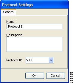
Step 3 ![]() In the Name field, enter a unique name for the new protocol.
In the Name field, enter a unique name for the new protocol.
Step 4 ![]() (Optional) From the Protocol ID drop-down list, select an ID for the protocol.
(Optional) From the Protocol ID drop-down list, select an ID for the protocol.
The protocol ID must be an integer in the range from 5000 to 9998; lower values are reserved for protocols provided by Cisco SCA BB.
Note ![]() The system provides the value of the protocol ID. Do not modify this field.
The system provides the value of the protocol ID. Do not modify this field.
Step 5 ![]() Click OK.
Click OK.
The Protocol Settings dialog box closes.
The new protocol is displayed in the Protocols tab. You can now add protocol elements to it. See "How to Add Protocol Elements" section.
How to Edit Protocols
You can modify the parameters of a protocol, even those for those protocols that are included in the Console installation.
To add, modify, or delete protocol elements, see "Managing Protocol Elements" section.
Step 1 ![]() From the Classification tab in the left pane, choose Configuration > Classification > Protocols.
From the Classification tab in the left pane, choose Configuration > Classification > Protocols.
The Protocol Settings dialog box appears.
Step 2 ![]() In the Protocols tab, double-click a protocol.
In the Protocols tab, double-click a protocol.
A second Protocol Settings dialog box appears (Figure 7-22).
Figure 7-22 Protocol Settings
Step 3 ![]() Modify fields in the Protocol Settings dialog box.
Modify fields in the Protocol Settings dialog box.
•![]() In the Name field, enter a new name for the protocol.
In the Name field, enter a new name for the protocol.
•![]() From the Protocol ID drop-down list, select an ID for the protocol.
From the Protocol ID drop-down list, select an ID for the protocol.
The protocol ID must be an integer in the range from 5000 to 9998; lower values are reserved for protocols provided by Cisco SCA BB.
Note ![]() The system provides the protocol ID. Do not modify this field.
The system provides the protocol ID. Do not modify this field.
Step 4 ![]() Click OK.
Click OK.
The Protocol Settings dialog box closes.
The new values of the protocol parameters are saved.
Step 5 ![]() Click Close.
Click Close.
The Protocol Settings dialog box closes.
How to Delete Protocols
You can delete all protocols, even those protocols that are included in the Console installation.
Step 1 ![]() From the Classification tab in the left pane, choose Configuration > Classification > Protocols.
From the Classification tab in the left pane, choose Configuration > Classification > Protocols.
The Protocol Settings dialog box appears.
Step 2 ![]() In the Protocols tab, select a Protocol.
In the Protocols tab, select a Protocol.
Step 3 ![]() In the Protocols tab, click the Delete Protocol () icon.
In the Protocols tab, click the Delete Protocol () icon.
A Protocol Warning message appears (Figure 7-23).
Figure 7-23 Protocol Warning
Step 4 ![]() Click Yes.
Click Yes.
•![]() If any service element maps the selected protocol to a service (see "Managing Service Elements" section), a second Protocol Warning message appears (see Figure 7-24) (even if the service is not used by any package).
If any service element maps the selected protocol to a service (see "Managing Service Elements" section), a second Protocol Warning message appears (see Figure 7-24) (even if the service is not used by any package).
Figure 7-24 Protocol Warning
•![]() Click Yes.
Click Yes.
The Protocol is deleted from the Protocols tab.
Step 5 ![]() Click Close.
Click Close.
The Protocol Settings dialog box closes.
Managing Protocol Elements
A protocol is a collection of protocol elements.
To complete the definition of a protocol, you must define its protocol elements. A protocol element maps a specific signature, IP protocol, and port range to the selected protocol. Every protocol element in a service configuration must be unique.
If a traffic flow meets all of the following four criteria, it is mapped to a specific protocol:
•![]() The flow belongs to the specified signature of the protocol element.
The flow belongs to the specified signature of the protocol element.
•![]() The flow protocol is the specified IP protocol of the protocol element.
The flow protocol is the specified IP protocol of the protocol element.
•![]() (If the IP protocol is TCP or UDP) The destination port is within the specified port range of the protocol element.
(If the IP protocol is TCP or UDP) The destination port is within the specified port range of the protocol element.
•![]() The protocol element is the most specific protocol element satisfying the first three criteria.
The protocol element is the most specific protocol element satisfying the first three criteria.
How to Add Protocol Elements
You can add any number of protocol elements to a protocol.
Note ![]() When you set the parameters of the protocol element, the values of the parameters are saved as you enter them.
When you set the parameters of the protocol element, the values of the parameters are saved as you enter them.
Step 1 ![]() From the Classification tab in the left pane, choose Configuration > Classification > Protocols.
From the Classification tab in the left pane, choose Configuration > Classification > Protocols.
The Protocol Settings dialog box appears.
Step 2 ![]() In the Protocols tab, select a protocol.
In the Protocols tab, select a protocol.
Step 3 ![]() In the Protocol Elements tab, click the Add Protocol Element () icon.
In the Protocol Elements tab, click the Add Protocol Element () icon.
A protocol element is added to the protocol.
A new row, representing the protocol element, is added to the protocol element list in the Protocol Element tab.
Step 4 ![]() Click in the Signature cell of the protocol element, and then click the Browse button that appears in the cell.
Click in the Signature cell of the protocol element, and then click the Browse button that appears in the cell.
Note ![]() The default value (an asterisk, *) means that no signature checking is performed when testing whether a flow maps to this protocol element.
The default value (an asterisk, *) means that no signature checking is performed when testing whether a flow maps to this protocol element.
The Select a Signature dialog box appears (Figure 7-25), displaying a list of all signatures.
Figure 7-25 Select a Signature
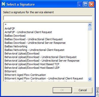
Step 5 ![]() Select a signature from the list.
Select a signature from the list.
Note ![]() Select the Generic signature to allow a flow that has no matching signature in the protocol signature database to be mapped to this protocol element (if the flow also matches the IP protocol and port range of the protocol element).
Select the Generic signature to allow a flow that has no matching signature in the protocol signature database to be mapped to this protocol element (if the flow also matches the IP protocol and port range of the protocol element).
Step 6 ![]() Click OK.
Click OK.
The Select a Signature dialog box closes.
The selected signature is displayed in the Signature cell of the Protocol Settings dialog box.
Step 7 ![]() Click in the IP Protocol cell of the protocol element, and then click the Browse button that appears in the cell.
Click in the IP Protocol cell of the protocol element, and then click the Browse button that appears in the cell.
Note ![]() The default value (an asterisk, *) means that no IP protocol checking is performed when testing whether a flow maps to this protocol element.
The default value (an asterisk, *) means that no IP protocol checking is performed when testing whether a flow maps to this protocol element.
The Select an IP Protocol dialog box appears (Figure 7-26), displaying a list of all IP protocols.
Figure 7-26 Select an IP Protocol
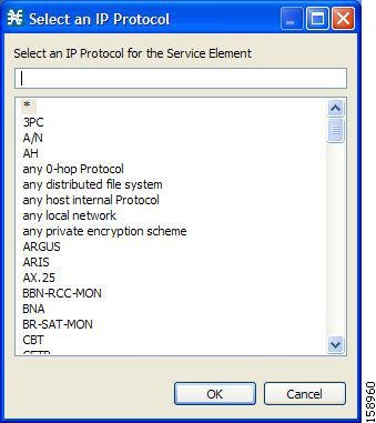
Step 8 ![]() Select an IP protocol from the list.
Select an IP protocol from the list.
Step 9 ![]() Click OK.
Click OK.
The Select an IP Protocol dialog box closes
The selected IP protocol is displayed in the IP Protocol cell of the Protocol Settings dialog box.
Step 10 ![]() In the Port Range cell, enter a port or range of ports. (For a range of ports, use a hyphen between the first and last ports in the range.)
In the Port Range cell, enter a port or range of ports. (For a range of ports, use a hyphen between the first and last ports in the range.)
Note ![]() Specifying a port range is only possible when the specified IP protocol is either TCP or UDP (or undefined, taking the wild-card value, *).
Specifying a port range is only possible when the specified IP protocol is either TCP or UDP (or undefined, taking the wild-card value, *).
Only a flow whose port matches one of these ports are mapped to this protocol element.
The protocol element is defined.
Step 11 ![]() Click Close.
Click Close.
The Protocol Settings dialog box closes.
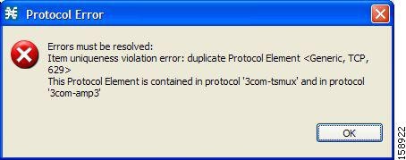
•![]() Instead, if the protocol element that you have defined is not unique in this service configuration, a Protocol Error message appears (Figure 7-27).
Instead, if the protocol element that you have defined is not unique in this service configuration, a Protocol Error message appears (Figure 7-27).
Figure 7-27 Protocol Error
a. ![]() Click OK.
Click OK.
b. ![]() Modify or delete the protocol element.
Modify or delete the protocol element.
c. ![]() Click Close.
Click Close.
The Protocol Settings dialog box closes.
How to Edit Protocol Elements
You can modify all protocol elements, even those protocol elements that are included in the Console installation.
Note ![]() All changes to the protocol element are saved as you make them.
All changes to the protocol element are saved as you make them.
Step 1 ![]() From the Classification tab in the left pane, choose Configuration > Classification > Protocols.
From the Classification tab in the left pane, choose Configuration > Classification > Protocols.
The Protocol Settings dialog box appears.
Step 2 ![]() In the Protocols tab, select a protocol.
In the Protocols tab, select a protocol.
Step 3 ![]() In the Protocol Elements tab, select a protocol element.
In the Protocol Elements tab, select a protocol element.
Step 4 ![]() Click in the Signature cell of the protocol element, and then click the Browse button that appears in the cell.
Click in the Signature cell of the protocol element, and then click the Browse button that appears in the cell.
The Select a Signature dialog box appears.
Step 5 ![]() Select a signature from the list.
Select a signature from the list.
Step 6 ![]() Click OK.
Click OK.
The Select a Signature dialog box closes.
Step 7 ![]() Click in the IP Protocol cell of the protocol element, and then click the Browse button that appears in the cell.
Click in the IP Protocol cell of the protocol element, and then click the Browse button that appears in the cell.
The Select an IP Protocol dialog box appears.
Step 8 ![]() Select an IP protocol from the list.
Select an IP protocol from the list.
Step 9 ![]() Click OK.
Click OK.
The Select an IP Protocol dialog box closes.
Step 10 ![]() In the Port Range cell of the protocol element, enter a port or range of ports.
In the Port Range cell of the protocol element, enter a port or range of ports.
Changes to the protocol element are saved as you make them.
Step 11 ![]() Click Close.
Click Close.
The Protocol Settings dialog box closes.
•![]() Instead, if the protocol element that you have modified is not unique in this service configuration, a Protocol Error message appears.
Instead, if the protocol element that you have modified is not unique in this service configuration, a Protocol Error message appears.
a. ![]() Click OK.
Click OK.
b. ![]() Modify or delete the protocol element.
Modify or delete the protocol element.
c. ![]() Click Close.
Click Close.
The Protocol Settings dialog box closes.
How to Delete Protocol Elements
You can delete all protocol elements, even those protocol elements that are included in the Console installation.
Step 1 ![]() From the Classification tab in the left pane, choose Configuration > Classification > Protocols.
From the Classification tab in the left pane, choose Configuration > Classification > Protocols.
The Protocol Settings dialog box appears.
Step 2 ![]() Select a protocol in the Protocols tab.
Select a protocol in the Protocols tab.
Step 3 ![]() In the Protocol Elements tab, select a protocol element.
In the Protocol Elements tab, select a protocol element.
Step 4 ![]() In the Protocol Elements tab, click the Delete Protocol Element () icon.
In the Protocol Elements tab, click the Delete Protocol Element () icon.
A Protocol Warning message appears (Figure 7-28).
Figure 7-28 Protocol Warning

Step 5 ![]() Click Yes.
Click Yes.
The protocol element is deleted from the Protocol Elements tab.
Step 6 ![]() Click Close.
Click Close.
The Protocol Settings dialog box closes.
Managing Zones
A zone is a collection of destination IP addresses; usually the addresses in one zone are related in some way.
Zones are used to classify network sessions; each network session is assigned to a service element based on its destination IP address.
A service configuration can contain up to 10,000 zone items on Cisco SCE 2000 and up to 20,000 on Cisco SCE 8000. Every zone item must be unique.
This section explains the following procedures:
•![]() Importing zones, see "How to Import Service Configuration Data" section
Importing zones, see "How to Import Service Configuration Data" section
•![]() Exporting zones, see "How to Export Service Configuration Data" section
Exporting zones, see "How to Export Service Configuration Data" section
BGP Autonomous System Dynamic Detection
The BGP Autonomous System (BGP AS) Dynamic Detection feature enables you to provision the BGP autonomous system as IP prefixes to the Cisco SCE zones.
With the BGP AS Dynamic Detection feature, you can:
•![]() Add the complete AS number node and all the IP prefixes under it to a new zone.
Add the complete AS number node and all the IP prefixes under it to a new zone.
•![]() Add the IP Prefixes obtained from the AS number nodes to an existing zone.
Add the IP Prefixes obtained from the AS number nodes to an existing zone.
•![]() Add IP prefixes to a new zone.
Add IP prefixes to a new zone.
•![]() Delete IP prefixes from a zone.
Delete IP prefixes from a zone.
For details, see the following sections:
•![]() BGP AS Dynamic Detection Workflow
BGP AS Dynamic Detection Workflow
•![]() Enabling BGP AS Dynamic Detection
Enabling BGP AS Dynamic Detection
•![]() Collecting and Storing the BGP Autonomous System (AS) Details
Collecting and Storing the BGP Autonomous System (AS) Details
•![]() Creating a New Zone with Select BGP AS Numbers and Prefixes
Creating a New Zone with Select BGP AS Numbers and Prefixes
•![]() Understanding BGP AS Numbers and Prefixes Color Schema
Understanding BGP AS Numbers and Prefixes Color Schema
•![]() Updating a Zone with Select BGP AS Numbers and Prefixes
Updating a Zone with Select BGP AS Numbers and Prefixes
•![]() Deleting IP Prefixes from a Zone
Deleting IP Prefixes from a Zone
How to View Zones
You can view a list of all zones and their associated zone items.
Step 1 ![]() From the Classification tab in the left pane, choose Configuration > Classification > Zones.
From the Classification tab in the left pane, choose Configuration > Classification > Zones.
The Zone Settings dialog box appears (Figure 7-29).
The Zones tab displays a list of all zones. The first zone in the list is selected, and its zone items are displayed in the Zone Items tab.
Figure 7-29 Zone Settings
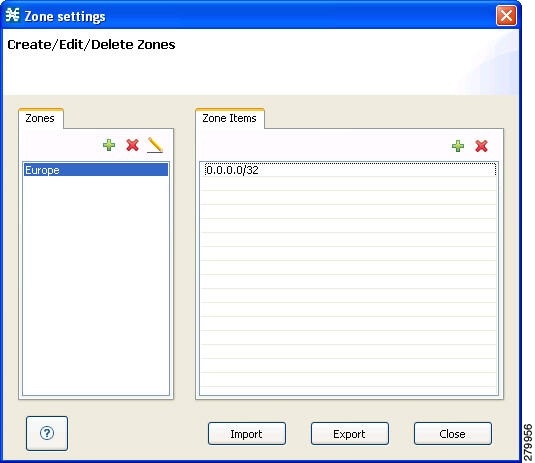
Step 2 ![]() Click a zone in the list to display its zone items.
Click a zone in the list to display its zone items.
The zone items of the selected zone are displayed in the Zone Items tab.
Step 3 ![]() Click Close.
Click Close.

Timesaver ![]() If you enable the automatic zone provisioning, an Advanced Import button will be available. Click the Advanced Import button to import the BGP AS numbers and prefixes to create Zones. See the "Creating a New Zone with Select BGP AS Numbers and Prefixes" section.
If you enable the automatic zone provisioning, an Advanced Import button will be available. Click the Advanced Import button to import the BGP AS numbers and prefixes to create Zones. See the "Creating a New Zone with Select BGP AS Numbers and Prefixes" section.
How to Add Zones
Step 1 ![]() From the Classification tab in the left pane, choose Configuration > Classification > Zones.
From the Classification tab in the left pane, choose Configuration > Classification > Zones.
The Zone Settings dialog box appears.
Step 2 ![]() In the Zones tab, click the Add Zone () icon.
In the Zones tab, click the Add Zone () icon.
The Zone Settings dialog box appears (Figure 7-30).
Figure 7-30 Zone Settings
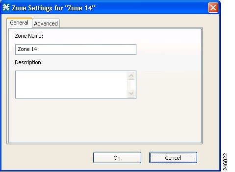
Step 3 ![]() In the Name field, enter a unique name for the new zone.
In the Name field, enter a unique name for the new zone.
Step 4 ![]() From the Advanced tab, from the Zone Index drop-down list, select an ID for the zone. The zone ID must be a positive integer in the range from 1 to 32767.
From the Advanced tab, from the Zone Index drop-down list, select an ID for the zone. The zone ID must be a positive integer in the range from 1 to 32767.
Note ![]() The system provides the value of the zone ID. Do not modify this field.
The system provides the value of the zone ID. Do not modify this field.
Figure 7-31 Zone Settings - Advanced Tab
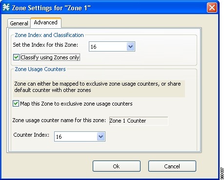
Step 5 ![]() (Optional) Check the Classify using zones only check box. Click Yes in the pop up window to confirm. If you enable this option, the Cisco SCE classifies the data flows based on the zone to which the data flows belong.
(Optional) Check the Classify using zones only check box. Click Yes in the pop up window to confirm. If you enable this option, the Cisco SCE classifies the data flows based on the zone to which the data flows belong.
Note ![]() If you enable this option on an existing zone, every service element that references the selected zone is deleted.
If you enable this option on an existing zone, every service element that references the selected zone is deleted.
Step 6 ![]() Check the Map this Zone to exclusive zone usage counters check box to map the Zone to exclusive zone usage counters, or share default counter with other zones.
Check the Map this Zone to exclusive zone usage counters check box to map the Zone to exclusive zone usage counters, or share default counter with other zones.
The Zone Settings dialog box appears (Figure 7-31).
Step 7 ![]() From the Counter Index drop-down list, select an index for the zone.
From the Counter Index drop-down list, select an index for the zone.
The Counter Index must be a positive integer in the range from 1 to 1023.
Step 8 ![]() Click OK.
Click OK.
The Zone Settings dialog box closes.
The new zone is added to the Zones tab. You can now add zone items. (See "How to Add Zone Items" section.)
How to Edit Zones
You can modify zone parameters at any time.
To add, modify, or delete zone items, see "Managing Zone Items" section.
Step 1 ![]() From the Classification tab in the left pane, choose Configuration > Classification > Zones.
From the Classification tab in the left pane, choose Configuration > Classification > Zones.
The Zone Settings dialog box appears.
Step 2 ![]() In the Zones tab, select a zone.
In the Zones tab, select a zone.
Step 3 ![]() Click the Edit Zone () icon.
Click the Edit Zone () icon.
The Zone Settings dialog box appears.
Step 4 ![]() Modify fields in the dialog box.
Modify fields in the dialog box.
•![]() In the Name field, enter a new name for the zone.
In the Name field, enter a new name for the zone.
•![]() From the Zone Index drop-down list, select an ID for the zone.
From the Zone Index drop-down list, select an ID for the zone.
The zone ID must be a positive integer in the range from 1 to 32767.
Note ![]() The system provides the value of the zone ID. Do not modify this field.
The system provides the value of the zone ID. Do not modify this field.
Step 5 ![]() Click OK.
Click OK.
The Zone Settings dialog box closes.
The new values of the zone parameters are saved.
Step 6 ![]() Click Close.
Click Close.
The Zone Settings dialog box closes.
How to Delete Zones
You can delete any or all zones.
Step 1 ![]() From the Classification tab in the left pane, choose Configuration > Classification > Zones.
From the Classification tab in the left pane, choose Configuration > Classification > Zones.
The Zone Settings dialog box appears.
Step 2 ![]() In the Zones tab, select a zone.
In the Zones tab, select a zone.
Step 3 ![]() In the Zones tab, click the Delete Zone () icon.
In the Zones tab, click the Delete Zone () icon.
A Zone Warning message appears (Figure 7-32).
Figure 7-32 Zone Warning
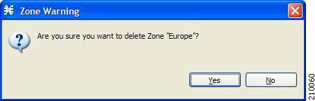
Step 4 ![]() Click OK.
Click OK.
•![]() If any service element references the selected zone, a second Zone Warning message appears (Figure 7-33).
If any service element references the selected zone, a second Zone Warning message appears (Figure 7-33).
Figure 7-33 Zone Warning
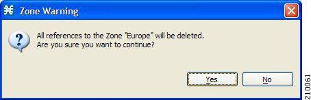
•![]() Click Yes.
Click Yes.
Every service element that references the selected zone is deleted.
The zone is deleted and is no longer displayed in the Zones tab.
Step 5 ![]() Click Close.
Click Close.
The Zone Settings dialog box closes.
Managing Zone Items
A zone is a collection of related zone items. A zone item is an IP address or a range of IP addresses.
A service configuration can contain up to 20,000 zone items on SCE8000 and up to 10,000 zone items on SCE2000. Every zone item must be unique.
How to Add Zone Items
You can add several zone items to a zone. The limit is 10,000 zone items per service configuration on Cisco SCE 2000 and 20,000 zone items per service configuration on Cisco SCE 8000. From Cisco SCA BB Release 3.8.0, software-based support for IPv6 zones is available on Cisco SCE 8000 devices. You can add up to 5000 IPv6 zones per Cisco SCE 8000 device.
Step 1 ![]() From the Classification tab in the left pane, choose Configuration > Classification > Zones.
From the Classification tab in the left pane, choose Configuration > Classification > Zones.
The Zone Settings dialog box appears.
Step 2 ![]() In the Zones tab, select a zone.
In the Zones tab, select a zone.
Step 3 ![]() In the Zone Items tab, click the Add Zone Item () icon.
In the Zone Items tab, click the Add Zone Item () icon.
A new line is added to the Zone Items table.
Step 4 ![]() Double-click the new list item and enter a valid value.
Double-click the new list item and enter a valid value.
A valid value is either a single IP address (for example, 63.111.106.7 or ABCD:1111:97EF:F641:0F2A:ABCD:1111:97EF) or a range of IP addresses (for example, 194.90.12.0/24 or ABCD:1111:97EF:F641:0F2A:ABCD:1111:97EF/128). For IPv6 zones, the valid range is from 0 to 128.
Step 5 ![]() Repeat Steps 3 and 4 for other IP addresses that are part of this zone.
Repeat Steps 3 and 4 for other IP addresses that are part of this zone.
Step 6 ![]() Click Close.
Click Close.
The Zone Settings dialog box closes.
•![]() Instead, if the zone item that you have defined is not unique in this service configuration, a Zone Error message appears (Figure 7-34).
Instead, if the zone item that you have defined is not unique in this service configuration, a Zone Error message appears (Figure 7-34).
Figure 7-34 Zone Error
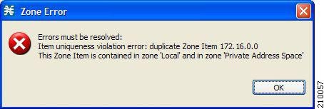
a. ![]() Click OK.
Click OK.
b. ![]() Modify or delete the zone item.
Modify or delete the zone item.
c. ![]() Click Close.
Click Close.
The Zone Settings dialog box closes.
How to Edit Zone Items
Step 1 ![]() From the Classification tab in the left pane, choose Configuration > Classification > Zones.
From the Classification tab in the left pane, choose Configuration > Classification > Zones.
The Zone Settings dialog box appears.
Step 2 ![]() In the Zones tab, select a zone.
In the Zones tab, select a zone.
Step 3 ![]() In the Zone Items tab, double-click a zone item.
In the Zone Items tab, double-click a zone item.
Step 4 ![]() Enter a new value for the zone item.
Enter a new value for the zone item.
A valid value is either a single IP address (for example, 63.111.106.7 or ABCD:1111:97EF:F641:0F2A:ABCD:1111:97EF) or a range of IP addresses (for example, 194.90.12.0/24 or ABCD:1111:97EF:F641:0F2A:ABCD:1111:97EF/128). For IPv6 zones, the valid range is from 0 to 128.
Step 5 ![]() Click Close.
Click Close.
The Zone Settings dialog box closes.
•![]() Instead, if the zone item that you have modified is not unique in this service configuration, a Zone Error message appears.
Instead, if the zone item that you have modified is not unique in this service configuration, a Zone Error message appears.
a. ![]() Click OK.
Click OK.
b. ![]() Modify or delete the zone item.
Modify or delete the zone item.
c. ![]() Click Close.
Click Close.
The Zone Settings dialog box closes.
How to Delete Zone Items
Step 1 ![]() From the Classification tab in the left pane, choose Configuration > Classification > Zones.
From the Classification tab in the left pane, choose Configuration > Classification > Zones.
The Zone Settings dialog box appears.
Step 2 ![]() In the Zones tab, select a zone.
In the Zones tab, select a zone.
Step 3 ![]() In the Zone Items tab, select a zone item.
In the Zone Items tab, select a zone item.
Step 4 ![]() In the Zone Items tab, click the Delete Zone Item () icon.
In the Zone Items tab, click the Delete Zone Item () icon.
The zone item is deleted.
Step 5 ![]() Click Close.
Click Close.
The Zone Settings dialog box closes.
BGP AS Dynamic Detection Workflow
This section provides details on the BGP AS Dynamic Detection workflow:
1. ![]() When you run the asFetch.bat script, the script downloads the AS number and IP prefixes from the configured BGP router using the SNMP MIBs
When you run the asFetch.bat script, the script downloads the AS number and IP prefixes from the configured BGP router using the SNMP MIBs
2. ![]() The script converts the prefixes to IP ranges and stores the details in a local file. If you configure a scheduler to run the script periodically, during each run, the IP file gets overwritten with a new one.
The script converts the prefixes to IP ranges and stores the details in a local file. If you configure a scheduler to run the script periodically, during each run, the IP file gets overwritten with a new one.
3. ![]() Cisco SCA BB:
Cisco SCA BB:
a. ![]() Maps each zone name to the parameter of SCA BB zone configuration, such as Zone Index.
Maps each zone name to the parameter of SCA BB zone configuration, such as Zone Index.
b. ![]() Pushes parameters such as zone and zone items (BGP routes) to the Cisco SCE while applying the configuration.
Pushes parameters such as zone and zone items (BGP routes) to the Cisco SCE while applying the configuration.
c. ![]() Configures the Services configured on various zones and pushes the configuration to the Cisco SCE.
Configures the Services configured on various zones and pushes the configuration to the Cisco SCE.
4. ![]() Cisco SCE controls the service bandwidth based on the services configured on various zones.
Cisco SCE controls the service bandwidth based on the services configured on various zones.
Enabling BGP AS Dynamic Detection
By default, BGP AS Dynamic Detection is disabled on Cisco SCA BB.
To enable BGP AS Dynamic Detection, complete these steps:
Step 1 ![]() Choose Windows > Preferences.
Choose Windows > Preferences.
Step 2 ![]() In the Preferences window, expand the Service Configuration.
In the Preferences window, expand the Service Configuration.
Step 3 ![]() Click Automatic Zone Provisioning.
Click Automatic Zone Provisioning.
Step 4 ![]() Check the Enable Automatic Zone Provisioning check box.
Check the Enable Automatic Zone Provisioning check box.
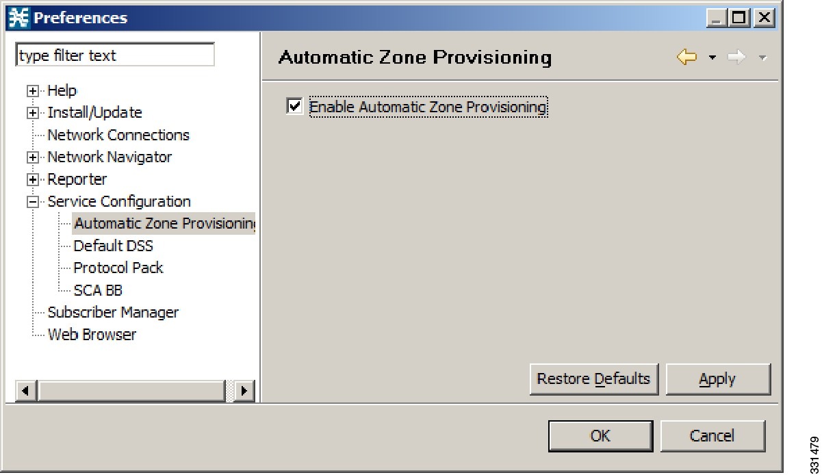
Step 5 ![]() Click Apply.
Click Apply.
Step 6 ![]() Click OK.
Click OK.
Collecting and Storing the BGP Autonomous System (AS) Details
The Cisco SCA BB asFetch script uses SNMP MIBs to fetch the BGP AS numbers and prefixes. Cisco SCA BB, Release 3.7.2, supports only SNMP version 2.
The routerInfo.properties file, asFetch.bat, and asFetch.sh are in the sca_bb_util\bin folder.
To collect and store the BGP AS details, complete these steps:
Step 1 ![]() Enter the router IP and SNMP community string in the routerInfo.properties file.
Enter the router IP and SNMP community string in the routerInfo.properties file.
Step 2 ![]() Run the asFetch.bat script.
Run the asFetch.bat script.
The script fetches the AS number and IP prefix details and saves them in the BGPRouter<number>.csv file that is present in the same folder in which you have extracted the asFetch script. Prior to performing Step 2, ensure that the following prerequisites are fulfilled:
–![]() If AS numbers and IP prefixes have to be generated for more than one router IP, enter the router IP address of the community string separated by a comma (,) in the routerInfo.properties file.
If AS numbers and IP prefixes have to be generated for more than one router IP, enter the router IP address of the community string separated by a comma (,) in the routerInfo.properties file.
–![]() Run the asFetch.bat file to generate the BGPRouter<number>.csv files based on the number of IP addresses entered in the properties file. For example, if two IP addresses are specified in the properties file, The BGPRouter1.csv and BGPRouter2.csv files get generated.These .csv files contain the AS number and IP prefix details. These files can be imported from the Zone settings window.
Run the asFetch.bat file to generate the BGPRouter<number>.csv files based on the number of IP addresses entered in the properties file. For example, if two IP addresses are specified in the properties file, The BGPRouter1.csv and BGPRouter2.csv files get generated.These .csv files contain the AS number and IP prefix details. These files can be imported from the Zone settings window.
You can run the script manually or use a scheduler to run the script periodically.
Creating a New Zone with Select BGP AS Numbers and Prefixes
Before attempting to add the BGP AS numbers and prefixes to zones, enable automatic zone provisioning and run the asFetch script to get the BGP AS details into the BGPRouter<number>.csv file.
To create a new zone and add select BGP AS numbers and prefixes, complete the following steps:
Step 1 ![]() From the Service Configuration Editor window, choose Configuration > Classification > Zones.
From the Service Configuration Editor window, choose Configuration > Classification > Zones.
Step 2 ![]() In the Zone Settings window, click Advanced Import.
In the Zone Settings window, click Advanced Import.
Step 3 ![]() Browse to the folder in which the BGPRouter<number>.csv file is saved, and select the BGPRouter<number>.csv file.
Browse to the folder in which the BGPRouter<number>.csv file is saved, and select the BGPRouter<number>.csv file.
Step 4 ![]() Click Open.
Click Open.
The AS No & Prefixes dialog box appears.

Step 5 ![]() Select the corresponding AS Number.
Select the corresponding AS Number.
Step 6 ![]() Click Add.
Click Add.
Step 7 ![]() Enter a New Zone Name.
Enter a New Zone Name.
Step 8 ![]() Click OK.
Click OK.
Step 9 ![]() Click OK.
Click OK.
Understanding BGP AS Numbers and Prefixes Color Schema
The AS Number and Prefixes dialog box uses various colors to indicate new prefixes, prefixes added to a zone, or changes to the AS Number to which the prefix belongs.
Green color indicates a new prefix that does not belong to any zone. After you add the prefix to a zone, the color of the prefix in the prefix list and the zone changes to black. If you remove the prefix from the zone, the color of the prefix in the prefix list changes to green again.
Blue color indicates that the prefix has moved from one AS to another. This helps you decide whether to move the prefix to another zone.
Red color indicates that the prefix is not a part of the AS Numbers and Prefixes list.
Updating a Zone with Select BGP AS Numbers and Prefixes
To update a zone with select BGP AS numbers and prefixes, complete the following steps:
Step 1 ![]() From the Service Configuration Editor window, choose Configuration > Classification > Zones.
From the Service Configuration Editor window, choose Configuration > Classification > Zones.
Step 2 ![]() In the Zone Settings window, click Advanced Import.
In the Zone Settings window, click Advanced Import.
Step 3 ![]() Browse to the folder in which the BGPRouter<number>.csv file is saved and select the BGPRouter<number>.csv file.
Browse to the folder in which the BGPRouter<number>.csv file is saved and select the BGPRouter<number>.csv file.
Step 4 ![]() Click Open.
Click Open.
The AS No & Prefixes dialog box appears.
Step 5 ![]() Select the corresponding AS Number.
Select the corresponding AS Number.
Step 6 ![]() Click Update.
Click Update.
Step 7 ![]() Choose a zone from the drop-down list.
Choose a zone from the drop-down list.
Step 8 ![]() Click OK.
Click OK.
Step 9 ![]() Click OK.
Click OK.
Timesaver ![]() From the AS No & Prefixes dialog box, you can drag and drop the required AS numbers and IP prefixes to the required zones.
From the AS No & Prefixes dialog box, you can drag and drop the required AS numbers and IP prefixes to the required zones.
Deleting IP Prefixes from a Zone
You can delete IP prefixes only from a zone and not from the AS Numbers and Prefixes list.
To delete IP prefixes from a zone:
Step 1 ![]() Select the prefixes you want to delete.
Select the prefixes you want to delete.
Step 2 ![]() Click Delete.
Click Delete.
Managing Protocol Signatures
A protocol signature is a set of parameters that uniquely identify a protocol.
Viewing Signatures
•![]() How to Filter the Signatures List
How to Filter the Signatures List
How to View Signatures
You can view a list of all signatures and the protocol to which each is assigned.
Step 1 ![]() From the Classification tab in the left pane, choose Configuration > Classification > Signatures Settings.
From the Classification tab in the left pane, choose Configuration > Classification > Signatures Settings.
The Signatures Settings dialog box appears (Figure 7-35).
Figure 7-35 Signatures Settings
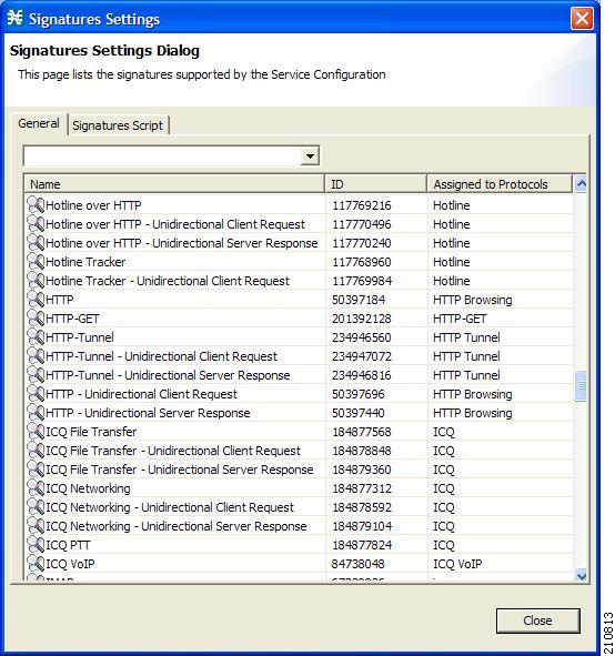
Step 2 ![]() Click Close.
Click Close.
The Signatures Settings dialog box closes.
How to Filter the Signatures List
You can filter the signature by type, so that the Signatures Settings dialog box lists only the selected type of signature.
The signature categories are:
•![]() DSS Contributed Signatures
DSS Contributed Signatures
•![]() Not Assigned to any Protocol
Not Assigned to any Protocol
•![]() P2P Signatures
P2P Signatures
•![]() VoIP Signatures
VoIP Signatures
•![]() SIP Signatures
SIP Signatures
•![]() Worm Signatures
Worm Signatures
•![]() Packet Stream Pattern Based Protocols Signatures
Packet Stream Pattern Based Protocols Signatures
•![]() Unidirectionally Detected Signatures
Unidirectionally Detected Signatures
•![]() Behavioral Signatures
Behavioral Signatures
•![]() E-Mail and Newsgroups Signatures
E-Mail and Newsgroups Signatures
•![]() Gaming Signatures
Gaming Signatures
•![]() HTTP Signatures
HTTP Signatures
•![]() Instant Messaging Signatures
Instant Messaging Signatures
•![]() Net Admin Signatures
Net Admin Signatures
•![]() Video Signatures
Video Signatures
•![]() Tunneling Signatures
Tunneling Signatures
•![]() ClickStream Signatures
ClickStream Signatures
Note ![]() Some signatures belong to more than one category.
Some signatures belong to more than one category.
Step 1 ![]() From the Console main menu, choose Configuration > Classification > Signatures Settings.
From the Console main menu, choose Configuration > Classification > Signatures Settings.
The Signatures Settings dialog box appears.
Step 2 ![]() From the drop-down list, select the type of signature to display.
From the drop-down list, select the type of signature to display.
The signatures of the selected type appear in the dialog box.
Step 3 ![]() Click Close.
Click Close.
The Signatures Settings dialog box closes.
Dynamic Signatures
New protocols are being introduced all the time. Dynamic signatures is a mechanism that allows new protocols to be added to the protocol list and, from there, to service configurations. Dynamic Signature is especially useful for classifying the traffic of a new protocol (for example, a new P2P protocol in a P2P-Control solution).
•![]() Installing new signatures to an active service configuration is described in Working with Protocol Packs.
Installing new signatures to an active service configuration is described in Working with Protocol Packs.
•![]() Creating and modifying signatures is described in Using the Signature Editor.
Creating and modifying signatures is described in Using the Signature Editor.
•![]() Using servconf, the Cisco SCA BB Server Configuration Utility, to apply signatures is described in The Cisco SCA BB Service Configuration Utility.
Using servconf, the Cisco SCA BB Server Configuration Utility, to apply signatures is described in The Cisco SCA BB Service Configuration Utility.
The following sections describe working with dynamic signatures in the Service Configuration Editor.
•![]() Dynamic Signature Script Files.
Dynamic Signature Script Files.
Dynamic Signature Script Files
Dynamic signatures are provided in special Dynamic Signatures Script (DSS) files that you can add to a service configuration using either the Console or the Service Configuration API. After a DSS file is imported into a service configuration, the new protocols it describes:
•![]() Appear in the protocol list.
Appear in the protocol list.
•![]() May be added to services.
May be added to services.
•![]() Are used when viewing reports.
Are used when viewing reports.
To simplify the configuration of new protocols added by a DSS, the DSS may specify a Buddy Protocol for a new protocol. If, when loading a DSS, the application encounters the Buddy Protocol, it automatically duplicates the set of service elements that use the Buddy Protocol, and replaces all references to the Buddy Protocol with references to the new protocol. The association of the new protocol to services matches that of the Buddy Protocol.
The following configuration actions are performed automatically when you import a DSS into a service configuration:
•![]() Signatures are updated and new signatures are loaded.
Signatures are updated and new signatures are loaded.
•![]() Protocol elements are created for new signatures of existing protocols.
Protocol elements are created for new signatures of existing protocols.
•![]() New protocols are added to the protocol list, and protocol elements are created for them.
New protocols are added to the protocol list, and protocol elements are created for them.
•![]() Service elements are created for new protocols according to the configuration of Buddy Protocols.
Service elements are created for new protocols according to the configuration of Buddy Protocols.
The import procedure preserves all service and protocol settings.
Note ![]() After importing a DSS, associate the newly added protocols with services.
After importing a DSS, associate the newly added protocols with services.
Cisco or its partners releases DSS files periodically in accordance with customer requirements and market needs.
DSS files contain new protocols and signatures, and update previously defined signatures. Updating a service configuration with the new DSS is explained in How to Import a Dynamic Signature Script into a Service Configuration.
Note ![]() You can create your own DSS files or modify the Cisco release DSS file using the Signature Editor tool (see "Managing DSS Files" section).
You can create your own DSS files or modify the Cisco release DSS file using the Signature Editor tool (see "Managing DSS Files" section).
•![]() How to View Information About the Current Dynamic Signatures
How to View Information About the Current Dynamic Signatures
•![]() How to Import a Dynamic Signature Script into a Service Configuration
How to Import a Dynamic Signature Script into a Service Configuration
•![]() How to Remove Dynamic Signatures
How to Remove Dynamic Signatures
How to View Information About the Current Dynamic Signatures
Step 1 ![]() From the Classification tab in the left pane, choose Configuration > Classification > Signatures Settings.
From the Classification tab in the left pane, choose Configuration > Classification > Signatures Settings.
The Signatures Settings dialog box appears.
Step 2 ![]() Click the Signatures Script tab.
Click the Signatures Script tab.
The Signatures Script tab opens (Figure 7-36).
•![]() If no DSS file was imported into the current service configuration, the Signatures Settings dialog box displays a message informing you of this.
If no DSS file was imported into the current service configuration, the Signatures Settings dialog box displays a message informing you of this.
Figure 7-36 Signature Settings
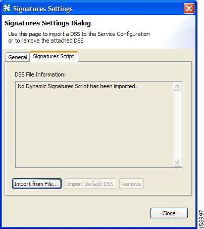
•![]() If a DSS file was imported into the current service configuration, the Signatures Settings dialog box displays information about the current dynamic signatures and the DSS file from which they were imported (Figure 7-37).
If a DSS file was imported into the current service configuration, the Signatures Settings dialog box displays information about the current dynamic signatures and the DSS file from which they were imported (Figure 7-37).
Figure 7-37 Signature Settings
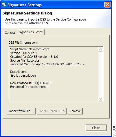
Step 3 ![]() Click Close.
Click Close.
The Signatures Settings dialog box closes.
How to Import a Dynamic Signature Script into a Service Configuration
You can import signatures into a service configuration from a DSS file provided by Cisco or one of its partners (described in this section), or from a DSS file that you have created or modified using the Signature Editor tool (see "Managing DSS Files" section).
Note ![]() It is recommended that you import the latest default DSS file (see "How to Import the Default DSS File Automatically" section) when creating a service configuration, and that you use this option only to apply a new DSS to existing service configuration.
It is recommended that you import the latest default DSS file (see "How to Import the Default DSS File Automatically" section) when creating a service configuration, and that you use this option only to apply a new DSS to existing service configuration.
Step 1 ![]() From the Classification tab in the left pane, choose Configuration > Classification > Signatures Settings.
From the Classification tab in the left pane, choose Configuration > Classification > Signatures Settings.
The Signatures Settings dialog box appears.
Step 2 ![]() Click the Signatures Script tab.
Click the Signatures Script tab.
The Signatures Script tab opens.
Step 3 ![]() Click Import from File.
Click Import from File.
An Import Warning message appears (Figure 7-38).
Figure 7-38 Import Warning
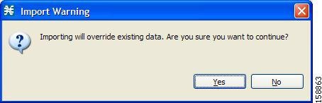
Step 4 ![]() Click Yes.
Click Yes.
The Import from file dialog box appears.
Step 5 ![]() Browse to the DSS file and click Open.
Browse to the DSS file and click Open.
The Import from file dialog box closes.
The signatures in the DSS file are imported into the service configuration.
Information about the imported signatures and their DSS file is displayed in the Signatures Settings dialog box.
Step 6 ![]() Click Close.
Click Close.
The Signatures Settings dialog box closes.
How to Remove Dynamic Signatures
You can remove the installed dynamic signatures from a service configuration.
Note ![]() The DSS file is not deleted.
The DSS file is not deleted.
Step 1 ![]() From the Classification tab in the left pane, choose Configuration > Classification > Signatures Settings.
From the Classification tab in the left pane, choose Configuration > Classification > Signatures Settings.
The Signatures Settings dialog box appears.
Step 2 ![]() Click the Signatures Script tab.
Click the Signatures Script tab.
The Signatures Script tab opens.
Step 3 ![]() Click Remove.
Click Remove.
A Dynamic Signature Script Confirmation message appears (Figure 7-39).
Figure 7-39 Dynamic Signature Script Confirmation
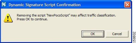
Step 4 ![]() Click OK.
Click OK.
•![]() If any service element references a protocol whose signature is included in the imported DSS file, a Dynamic Signature Script Removal Error message appears (Figure 7-40).
If any service element references a protocol whose signature is included in the imported DSS file, a Dynamic Signature Script Removal Error message appears (Figure 7-40).
Figure 7-40 Dynamic Signature Script Removal Error
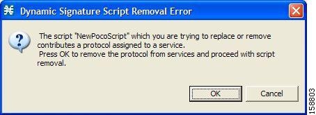
•![]() Click Yes.
Click Yes.
Every service element that references a protocol whose signature is included in the imported DSS file is deleted.
The dynamic signatures are removed from the service configuration.
The Remove button is dimmed.
If the dynamic signatures were imported from the default DSS file, the Import Default DSS button is enabled.
Step 5 ![]() Click Close.
Click Close.
The Signatures Settings dialog box closes.
The Default DSS File
Whenever a protocol pack becomes available from Cisco (or one of its partners), you should update offline service configurations (stored as PQB files on the workstation). The protocol pack (see "Protocol Packs" section) is provided as either an SPQI file or a DSS file.
You can either offer updates automatically to every service configuration created or edited at the workstation, or apply them from the workstation to the Cisco SCE platform. You make the latest update available by installing the most recent DSS or SPQI file as the default DSS file. You can install the file on the workstation either from the Console or by using The Cisco SCA BB Signature Configuration Utility.
•![]() The default DSS file is automatically offered for import when you perform any service configuration operation (such as creating a new service configuration or editing an existing one) from the Console on a service configuration that was not yet updated.
The default DSS file is automatically offered for import when you perform any service configuration operation (such as creating a new service configuration or editing an existing one) from the Console on a service configuration that was not yet updated.
•![]() The default DSS file is imported by default when any service configuration operation (such as applying an existing service configuration) is performed using servconf, The Cisco SCA BB Signature Configuration Utility. You can disable this option.
The default DSS file is imported by default when any service configuration operation (such as applying an existing service configuration) is performed using servconf, The Cisco SCA BB Signature Configuration Utility. You can disable this option.
Note ![]() Users are expected to update the default DSS on their management workstation whenever they obtain a new protocol pack, as explained in the following section.
Users are expected to update the default DSS on their management workstation whenever they obtain a new protocol pack, as explained in the following section.
•![]() Setting and Clearing the Default DSS File
Setting and Clearing the Default DSS File
•![]() Importing Dynamic Signatures from the Default DSS File
Importing Dynamic Signatures from the Default DSS File
Setting and Clearing the Default DSS File
The default DSS file should normally be the latest protocol pack provided by Cisco (or one of its partners). If necessary, modify the protocol pack using the Signature Editor tool (see "How to Edit DSS Files" section) to add signatures of new protocols until they become available from Cisco.
Whenever a new protocol pack becomes available, set it as the default DSS file. There is no need to clear the current default DSS file; it is overwritten by the new protocol pack.
•![]() How to Set a Protocol Pack as the Default DSS File
How to Set a Protocol Pack as the Default DSS File
•![]() How to Clear the Default DSS File
How to Clear the Default DSS File
How to Set a Protocol Pack as the Default DSS File
Step 1 ![]() From the Console main menu, choose Window > Preferences.
From the Console main menu, choose Window > Preferences.
The Preferences dialog box appears (Figure 7-41).
Step 2 ![]() From the menu tree in the left pane of the dialog box, choose Service Configuration > Default DSS.
From the menu tree in the left pane of the dialog box, choose Service Configuration > Default DSS.
The Default DSS area opens in the right pane of the dialog box.
Figure 7-41 Preferences
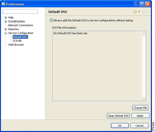
Step 3 ![]() Click Choose File.
Click Choose File.
An Open dialog box appears.
Step 4 ![]() From the Files of type drop-down list, select the file type of the protocol pack.
From the Files of type drop-down list, select the file type of the protocol pack.
Step 5 ![]() Browse to the protocol pack.
Browse to the protocol pack.
Step 6 ![]() Click Open.
Click Open.
The Open dialog box closes.
Information about the default DSS file is displayed in the Default DSS area of the Preferences dialog box (Figure 7-42).
Figure 7-42 Preferences - Default DSS
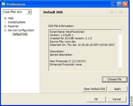
Step 7 ![]() Click OK.
Click OK.
The DSS file is copied to C:\Documents and Settings\<username>\.p-cube\default3.6.5.dss as the default DSS file. In Windows 7, the DSS file is copied to C:\Users\<username>\.p-cube\.
The Preferences dialog box closes.
How to Clear the Default DSS File
Step 1 ![]() From the Console main menu, choose Window > Preferences.
From the Console main menu, choose Window > Preferences.
The Preferences dialog box appears.
Step 2 ![]() From the menu tree in the left pane of the dialog box, choose Service Configuration > Default DSS.
From the menu tree in the left pane of the dialog box, choose Service Configuration > Default DSS.
The Default DSS area opens in the right pane of the dialog box.
Step 3 ![]() Click Clear Default DSS.
Click Clear Default DSS.
The default DSS file, C:\Documents and Settings\<username>\.p-cube\default3.6.5.dss, is deleted. In Windows 7, the default DSS file is C:\Users\<username>\.p-cube\default3.6.5.dss.
All information is deleted from the Default DSS area.
Note ![]() Deleting the default DSS file does not remove the imported dynamic signatures from the current service configuration.
Deleting the default DSS file does not remove the imported dynamic signatures from the current service configuration.
Step 4 ![]() Click OK.
Click OK.
The Preferences dialog box closes.
Importing Dynamic Signatures from the Default DSS File
If a default DSS file is installed, the application offers to import the dynamic signatures from the file when you create a new service configuration or when you open an existing service configuration that has not imported the signatures. Alternatively, you can manually import the dynamic signatures.
•![]() How to Import the Default DSS File Automatically
How to Import the Default DSS File Automatically
•![]() How to Import the Default DSS File Manually
How to Import the Default DSS File Manually
How to Import the Default DSS File Automatically
Step 1 ![]() Open an existing service configuration or create a new one.
Open an existing service configuration or create a new one.
A Default Signature message appears (Figure 7-43).
Figure 7-43 Default Signature

Step 2 ![]() Click Yes to import the default DSS file; click No to continue without importing the default DSS file.
Click Yes to import the default DSS file; click No to continue without importing the default DSS file.
How to Import the Default DSS File Manually
Step 1 ![]() From the Classification tab in the left pane, choose Configuration > Classification > Signatures Settings.
From the Classification tab in the left pane, choose Configuration > Classification > Signatures Settings.
The Signatures Settings dialog box appears (Figure 7-44).
Step 2 ![]() Click the Signatures Script tab.
Click the Signatures Script tab.
The Signatures Script tab opens, with the Import Default DSS button enabled.
Figure 7-44 Signatures Settings
Step 3 ![]() Click Import Default DSS.
Click Import Default DSS.
An Import Warning message appears (Figure 7-45).
Figure 7-45 Import Warning
Step 4 ![]() Click Yes.
Click Yes.
The signatures in the default DSS file are imported into the service configuration.
The Import Default DSS button is dimmed.
Information about the imported signatures and the default DSS file is displayed in the Signatures Settings dialog box.
Step 5 ![]() Click Close.
Click Close.
The Signatures Settings dialog box closes.
Managing Flavors
Flavors are advanced classification elements that are used to classify network sessions.
Flavors are based on specific Layer 7 properties. For example, users can associate an HTTP flow with a service based on different parts of the destination URL of the flow.
Note ![]() When you configure flavors, you cannot configure < and > symbols to be part of a URL.
When you configure flavors, you cannot configure < and > symbols to be part of a URL.
Flavors are supported only for small number of protocols, and for each such protocol there are different applicable flavor types. Flavor types are listed in the table in the following section.
There is a maximum number of flavor items for each flavor type (see "Maximum Number of Flavor Items per Flavor Type" section). For each flavor type, every flavor item must be unique.
Note ![]() If unidirectional classification is enabled in the active service configuration, flavors are not used for traffic classification.
If unidirectional classification is enabled in the active service configuration, flavors are not used for traffic classification.
•![]() Importing Flavor, see How to Import Service Configuration Data
Importing Flavor, see How to Import Service Configuration Data
•![]() Exporting Flavor, see How to Export Service Configuration Data
Exporting Flavor, see How to Export Service Configuration Data
Flavor Types and Parameters
Flavors are advanced classification elements that classify network sessions according to signature-specific Layer 7 properties.
When Layer 7 application properties are used as session parameters, such as with an HTTP User Agent, They are treated as character strings.
Layer 7 parameter-based flavor items may apply to the Layer 7 prefix (parameter beginning), Layer 7 suffix (parameter end), or a combination of Layer 7 prefixes and suffixes. A partial string must be followed by "*" in a prefix and preceded by "*" in a suffix.
Table 7-1 lists available flavor types.
Note ![]() Composite Flavors are pairs of two defined flavors.
Composite Flavors are pairs of two defined flavors.
How to View Flavors
You can view a list of all flavors and their associated flavor items.
Step 1 ![]() From the Classification tab in the left pane, choose Configuration > Classification > Flavors.
From the Classification tab in the left pane, choose Configuration > Classification > Flavors.
The dialog box appears (Figure 7-46).
Figure 7-46 Flavor Settings
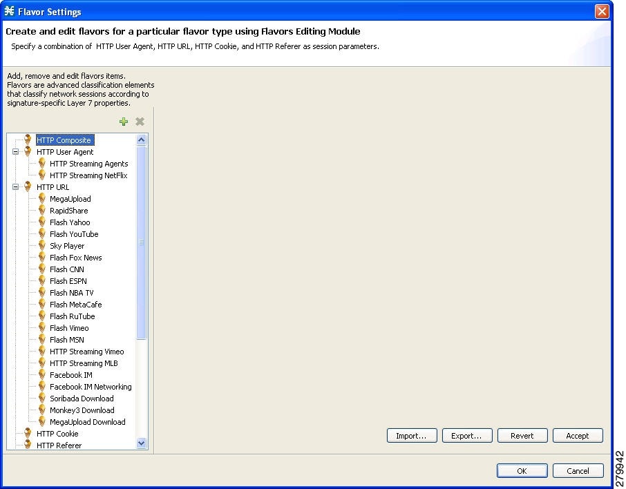
The left area displays a tree showing all flavors of each flavor type.
Step 2 ![]() Click a flavor in the tree to display its flavor items (Figure 7-47).
Click a flavor in the tree to display its flavor items (Figure 7-47).
Figure 7-47 Flavor Settings
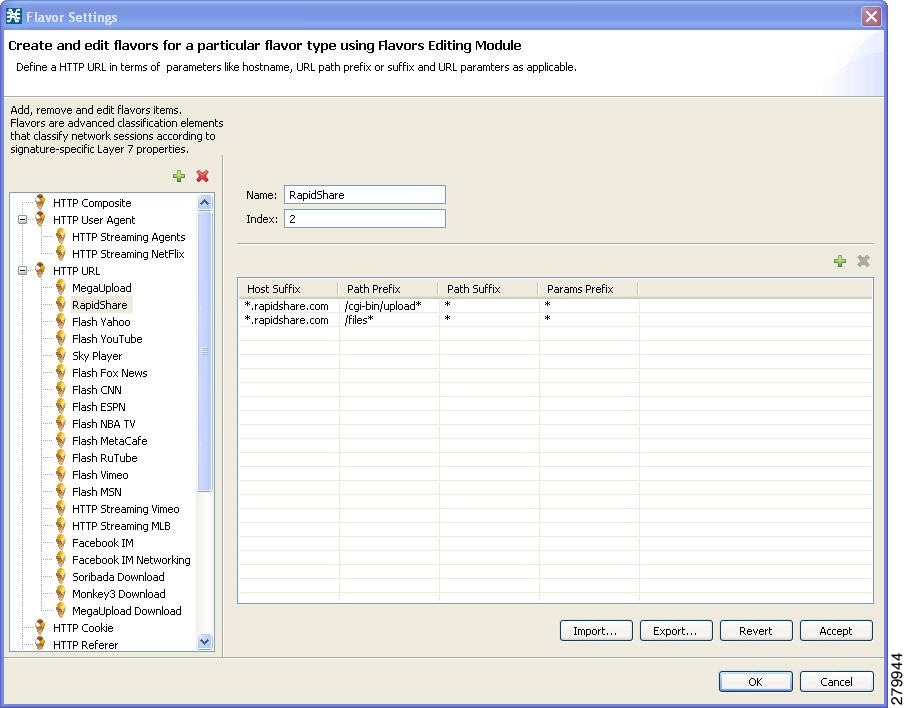
The flavor items are displayed in the right area.
Step 3 ![]() Click OK.
Click OK.
The Flavor Settings dialog box closes.
How to Add Flavors
You can import flavors from a CSV file. CSV files can be created by exporting flavors or created manually as described in the "CSV File Formats" chapter of Cisco Service Control Application Suite for Broadband Reference Guide.
You can add any number of flavors to a service configuration.
Step 1 ![]() From the Classification tab in the left pane, choose Configuration > Classification > Flavors.
From the Classification tab in the left pane, choose Configuration > Classification > Flavors.
The Flavor Settings dialog box appears (Figure 7-48).
Step 2 ![]() In the flavor tree, select a flavor type.
In the flavor tree, select a flavor type.
Step 3 ![]() Click the Add Flavor () icon.
Click the Add Flavor () icon.
A new flavor of the selected type is added to the flavor tree.
Figure 7-48 Flavor Settings - Adding Flavors
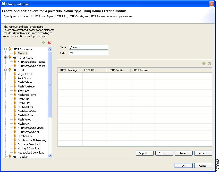
Step 4 ![]() In the Name field, enter a name for the new flavor.
In the Name field, enter a name for the new flavor.
Note ![]() You can use the default name for the flavor. It is recommended that you enter a meaningful name.
You can use the default name for the flavor. It is recommended that you enter a meaningful name.
Step 5 ![]() (Optional) In the Index field, enter a unique integer value.
(Optional) In the Index field, enter a unique integer value.
Note ![]() Cisco SCA BB provides a value for the Index. There is no need to change it.
Cisco SCA BB provides a value for the Index. There is no need to change it.
The flavor index must be a positive integer in the range from 1 to 2147483647.
You have defined the flavor. You can now add flavor items. (See "How to Add Flavor Items" section.)
How to Edit Flavors
You can modify flavor parameters at any time.
To add, modify, or delete flavor items, see "Managing Flavor Items" section.
Step 1 ![]() From the Classification tab in the left pane, choose Configuration > Classification > Flavors.
From the Classification tab in the left pane, choose Configuration > Classification > Flavors.
The Flavor Settings dialog box appears.
Step 2 ![]() In the flavor tree, select a flavor.
In the flavor tree, select a flavor.
The name and index of the flavor (and its flavor items) are displayed in the right area.
Step 3 ![]() Modify fields in the dialog box:
Modify fields in the dialog box:
•![]() In the Name field, enter a new name for the flavor.
In the Name field, enter a new name for the flavor.
•![]() In the Index field, enter a new, unique index for the flavor.
In the Index field, enter a new, unique index for the flavor.
The flavor index must be a positive integer in the range from 1 to 2147483647.
Step 4 ![]() Click OK.
Click OK.
The Flavor Settings dialog box closes.
How to Delete Flavors
You can delete any or all flavors.
Step 1 ![]() From the Classification tab in the left pane, choose Configuration > Classification > Flavors.
From the Classification tab in the left pane, choose Configuration > Classification > Flavors.
The Flavor Settings dialog box appears.
Step 2 ![]() In the flavor tree, right-click a flavor.
In the flavor tree, right-click a flavor.
A popup menu appears.
Step 3 ![]() Click the Delete () icon.
Click the Delete () icon.
A Confirm Delete message appears (Figure 7-49).
Figure 7-49 Confirm Delete
Step 4 ![]() Click OK.
Click OK.
•![]() If any service element references the selected flavor, a Confirm References Delete message appears (Figure 7-50).
If any service element references the selected flavor, a Confirm References Delete message appears (Figure 7-50).
Figure 7-50 Confirm References Deletion
•![]() Click Yes.
Click Yes.
Every service element that references the selected flavor is deleted.
The flavor is deleted and is no longer displayed in the flavor tree.
Step 5 ![]() Click Close.
Click Close.
The Flavor Settings dialog box closes.
Managing Flavor Items
A flavor is a collection of related flavor items.
A flavor item is a value of a property or properties of a flow. These properties depend on the flavor type (see "Flavor Types and Parameters" section).
There is a maximum number of flavor items for each flavor type. For each flavor type, every flavor item must be unique.
•![]() Maximum Number of Flavor Items per Flavor Type
Maximum Number of Flavor Items per Flavor Type
Maximum Number of Flavor Items per Flavor Type
Table 7-2 lists the maximum number of flavor items for each flavor type.
How to Add Flavor Items
You can add any number of flavor items to a flavor (subject to the limitation of the total number of each type of flavor item per service configuration, as listed in the previous section).
Step 1 ![]() From the Classification tab in the left pane, choose Configuration > Classification > Flavors.
From the Classification tab in the left pane, choose Configuration > Classification > Flavors.
The Flavor Settings dialog box appears (Figure 7-51).
Step 2 ![]() In the flavor tree, click a flavor.
In the flavor tree, click a flavor.
Step 3 ![]() Above the flavor item list, click the Create New Flavor Item icon.
Above the flavor item list, click the Create New Flavor Item icon.
Figure 7-51 Flavor Settings
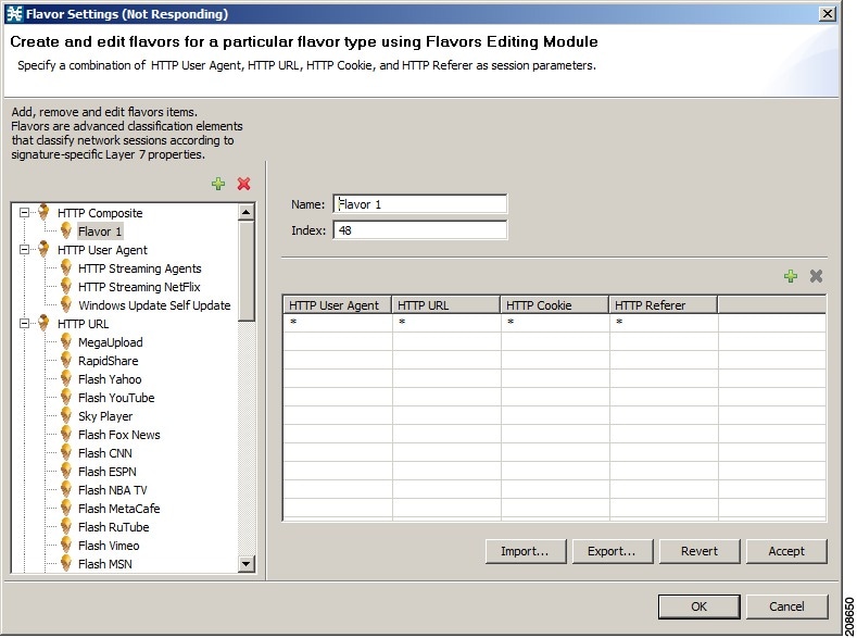
A new flavor item is added to the flavor item list. The number and type of parameters in the flavor item depend on the flavor type (see "Flavor Types and Parameters" section).
The new flavor item has a default value of all wild cards (*, asterisks).
Step 4 ![]() For each cell of the new flavor item, click the asterisk and then enter an appropriate value.
For each cell of the new flavor item, click the asterisk and then enter an appropriate value.
For composite flavors and for the HTTP Content Category flavor:
a. ![]() Click the asterisk.
Click the asterisk.
A Browse button is displayed in the cell.
b. ![]() Click the Browse button.
Click the Browse button.
A Select dialog box appears (Figure 7-52), displaying all valid values for the parameter.
Figure 7-52 Select an HTTP User Agent
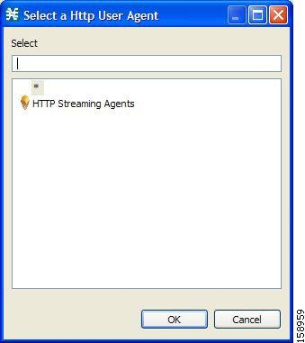
c. ![]() Select an appropriate value from the list.
Select an appropriate value from the list.
d. ![]() Click OK.
Click OK.
The Select dialog box closes.
The selected value is displayed in the cell.
Step 5 ![]() Repeat Steps 3 and 4 for other flavor items.
Repeat Steps 3 and 4 for other flavor items.
Step 6 ![]() Click OK.
Click OK.
The Flavor Settings dialog box closes.
How to Edit Flavor Items
Step 1 ![]() From the Classification tab in the left pane, choose Configuration > Classification > Flavors.
From the Classification tab in the left pane, choose Configuration > Classification > Flavors.
The Flavor Settings dialog box appears.
Step 2 ![]() In the flavor tree, select a flavor.
In the flavor tree, select a flavor.
Step 3 ![]() In the flavor item list, select a flavor item.
In the flavor item list, select a flavor item.
Step 4 ![]() For each cell of the selected flavor item, click the asterisk and then enter an appropriate value.
For each cell of the selected flavor item, click the asterisk and then enter an appropriate value.
For composite flavors and for the HTTP Content Category flavor:
a. ![]() Click the asterisk.
Click the asterisk.
A Browse button is displayed in the cell.
b. ![]() Click the Browse button.
Click the Browse button.
A Select dialog box appears, displaying all valid values for the parameter.
c. ![]() Select an appropriate value from the list.
Select an appropriate value from the list.
d. ![]() Click OK.
Click OK.
The Select dialog box closes.
The selected value is displayed in the cell.
Step 5 ![]() Click OK.
Click OK.
The Flavor Settings dialog box closes.
How to Delete Flavor Items
Step 1 ![]() From the Classification tab in the left pane, choose Configuration > Classification > Flavors.
From the Classification tab in the left pane, choose Configuration > Classification > Flavors.
The Flavor Settings dialog box appears.
Step 2 ![]() In the flavor tree, select a flavor.
In the flavor tree, select a flavor.
Step 3 ![]() In the flavor item list, right-click anywhere in a flavor item.
In the flavor item list, right-click anywhere in a flavor item.
A popup menu appears.
Step 4 ![]() Click the Delete () icon.
Click the Delete () icon.
The flavor item is deleted and is no longer displayed in the flavor item list.
Step 5 ![]() Click Close.
Click Close.
The Flavor Settings dialog box closes.
Example: How to Import a List of URLs and Block Them
The following example shows how to import a URL file and configure the Cisco SCE to block these URLs
Step 1 ![]() Create a new flavor under the HTTP URL flavor type, as described in How to Add Flavors.
Create a new flavor under the HTTP URL flavor type, as described in How to Add Flavors.
Step 2 ![]() Import a CSV file containing the URLS you wish to block.
Import a CSV file containing the URLS you wish to block.
For further information, see "How to Import Service Configuration Data" section.
Note ![]() The CSV file formats are described in the "CSV File Formats" chapter of Cisco Service Control Application Suit for Broadband Reference Guide.
The CSV file formats are described in the "CSV File Formats" chapter of Cisco Service Control Application Suit for Broadband Reference Guide.
Step 3 ![]() Define a Service.
Define a Service.
For further information, see "How to Add a Service to a Service Configuration" section.
Step 4 ![]() Within the defined Service, add a service element that uses the new Flavor.
Within the defined Service, add a service element that uses the new Flavor.
For further information, see "How to Add Service Elements" section.
Step 5 ![]() Add a rule to the package in which you want to block the URLs, and associate it with the new Service.
Add a rule to the package in which you want to block the URLs, and associate it with the new Service.
For further information, see "How to Add Rules to a Package" section.
Step 6 ![]() Configure the rule to block the flow.
Configure the rule to block the flow.
For further information, see "How to Define Per-Flow Actions for a Rule" section.
Managing Content Filtering
Content filtering involves classification and control of HTTP flows according to the requested URL. The classification of the URL is performed by accessing an external database.
Cisco SCA BB provides content filtering by integrating with a SurfControl Content Portal Authority (CPA) server.
Note ![]() Content filtering is not supported when unidirectional classification is enabled.
Content filtering is not supported when unidirectional classification is enabled.
•![]() Information About Content Filtering
Information About Content Filtering
•![]() How to Configure the RDR Formatter
How to Configure the RDR Formatter
•![]() How to Enter Line Interface Configuration Mode
How to Enter Line Interface Configuration Mode
•![]() Managing Content Filtering Settings
Managing Content Filtering Settings
Information About Content Filtering
The Cisco HTTP Content Filtering solution consists of:
•![]() The Cisco SCE application
The Cisco SCE application
•![]() The Cisco CPA client
The Cisco CPA client
•![]() The SurfControl CPA server
The SurfControl CPA server
The Cisco SCE application classifies each HTTP flow according to the category returned by the CPA server. This classification is then used for Cisco SCA BB traffic control and reporting. For example, you can define a rule to block browsing of the "Adult/Sexually Explicit" category or to generate reports on the volume consumed by browsing the "Kids" or "Shopping" categories.
The Cisco SCE Application
The Cisco service control application runs on the Cisco SCE platform. It forwards HTTP URLs that it extracts from traffic to the CPA client and uses the categorization results to classify the original HTTP flow to a service. This classification is then used for normal Cisco SCA BB traffic control and reporting.
The Cisco SCE application communicates with the CPA client using Raw Data Records (RDRs). See "How to Configure the RDR Formatter" section.
The Cisco CPA Client
The Cisco CPA client runs on the Cisco SCE platform. It sends URL queries to the CPA server for categorization, and updates Cisco SCA BB with the categorization results.
The CPA client is installed as part of the Cisco SCA BB application (PQI) installation. Use the Cisco SCE platform Command-Line Interface (CLI) (see "The Content Filtering CLI" section) to configure and monitor the client.
The SurfControl CPA Server
The CPA server runs on a dedicated machine. It receives categorization requests from the CPA client, connects to the SurfControl Content Database, and responds with the category ID of the queried URL.
The SurfControl CPA Server is installed on a separate server that must be accessible from the Cisco SCE platform. Details of the installation are not within the scope of this document.
The Content Filtering CLI
Use the Cisco SCE platform Command-Line Interface (CLI) to configure and monitor content filtering using SurfControl CPA. For more information about the Cisco SCE platform CLI, see the Cisco SCE8000 CLI Command Reference.
•![]() Description of CPA Client CLI Commands
Description of CPA Client CLI Commands
CPA Client CLI Commands
The commands listed here are explained in the following section.
•![]() Use the following CLI commands to configure the Cisco CPA client:
Use the following CLI commands to configure the Cisco CPA client:
[no] cpa-client
cpa-client destination
<address> [port <port>]
cpa-client retries
<number_of_retries>
•![]() These commands are line interface configuration commands. To run these commands you must enter line interface configuration mode (see "How to Enter Line Interface Configuration Mode" section).
These commands are line interface configuration commands. To run these commands you must enter line interface configuration mode (see "How to Enter Line Interface Configuration Mode" section).
•![]() Use the following CLI command in EXEC mode to monitor the status of the Cisco CPA client:
Use the following CLI command in EXEC mode to monitor the status of the Cisco CPA client:
show interface LineCard
<slot> cpa-client
Description of CPA Client CLI Commands
Table 7-3 gives a description of the Cisco CPA client CLI commands listed in the previous section and their default values.
Table 7-4 lists the information shown when monitoring the Cisco CPA client.
How to Configure the RDR Formatter
To enable the RDR formatter to issue HTTP categorization requests, configure the RDR formatter on the Cisco SCE platform.
Step 1 ![]() Make the appropriate Cisco SCE platform CLI command.
Make the appropriate Cisco SCE platform CLI command.
#>RDR-formatter destination 127.0.0.1 port 33001 category number 4 priority 100
Related Info
For more information about configuring the RDR formatter, see either the "Raw Data Formatting: The RDR Formatter and NetFlow Exporting" chapter of Cisco SCE8000 10GBE Software Configuration Guide or the "Raw Data Formatting: The RDR Formatter and NetFlow Exporting" chapter of Cisco SCE8000 GBE Software Configuration Guide.
How to Enter Line Interface Configuration Mode
To run line interface configuration commands you must enter line interface configuration mode and see the SCE(config if)# prompt displayed.
Step 1 ![]() At the Cisco SCE platform CLI prompt
At the Cisco SCE platform CLI prompt (SCE#), type configure.
Step 2 ![]() Press Enter.
Press Enter.
The SCE(config)# prompt appears.
Step 3 ![]() Type
Type interface LineCard 0.
Step 4 ![]() Press Enter.
Press Enter.
The SCE(config if)# prompt appears.
Managing Content Filtering Settings
Applying HTTP URL content filtering requires the following steps in the Service Configuration Editor:
1. ![]() Import the content filtering configuration file into your service configuration.
Import the content filtering configuration file into your service configuration.
By default, Cisco SCA BB creates a separate flavor (of type HTTP Content Category) for each content category and a service element for each new flavor. A new top-level service, "HTTP Browsing with Categories", is created, comprising these service elements.
2. ![]() Create new services and map the new category flavors to them.
Create new services and map the new category flavors to them.
3. ![]() Create additional rule entries for ClickStream services for each flavor.
Create additional rule entries for ClickStream services for each flavor.
You must configure ClickStream Services with the HTTP Browsing services for optimal HTTP content filtering.
4. ![]() Add content filtering rules to existing packages or create new packages that include content filtering rules.
Add content filtering rules to existing packages or create new packages that include content filtering rules.
5. ![]() Enable content filtering for selected packages.
Enable content filtering for selected packages.
6. ![]() Apply the service configuration.
Apply the service configuration.
•![]() Importing Content Filtering Categories
Importing Content Filtering Categories
•![]() How to Enable Content Filtering
How to Enable Content Filtering
•![]() How to View Content Filtering Settings
How to View Content Filtering Settings
•![]() How to Configure Content Filtering
How to Configure Content Filtering
•![]() How to Remove Content Filtering Settings
How to Remove Content Filtering Settings
Importing Content Filtering Categories
Before you can control HTTP flows based on content, you must import an XML file provided with the installation.
After you unzip the installation package, this file is located in the URL Filtering subfolder.
Note ![]() You cannot import content filtering categories when unidirectional classification is enabled.
You cannot import content filtering categories when unidirectional classification is enabled.
•![]() HTTP Content Category Flavors
HTTP Content Category Flavors
•![]() HTTP Browsing with Categories Service Elements
HTTP Browsing with Categories Service Elements
•![]() How to Import Content Filtering Categories Using the Import Dialog Box
How to Import Content Filtering Categories Using the Import Dialog Box
•![]() How to Import Content Filtering Categories Using the HTTP Content Filtering Settings Dialog Box
How to Import Content Filtering Categories Using the HTTP Content Filtering Settings Dialog Box
HTTP Content Category Flavors
By default, Cisco SCA BB creates a separate flavor (of type HTTP Content Category) for each content category when importing the XML file (Figure 7-53).
Figure 7-53 Flavor Settings
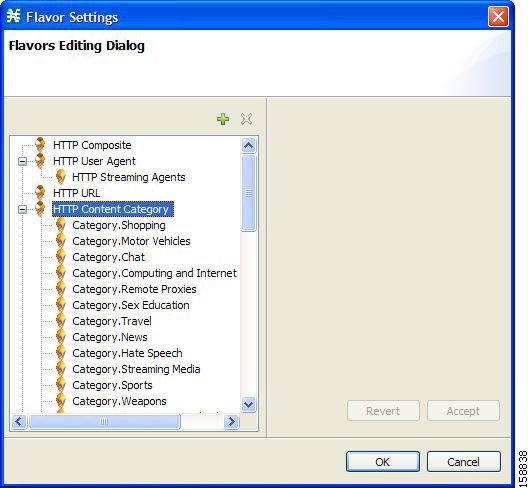
You can create additional HTTP Content Category Flavors that include two or more content categories. (See "How to Add Flavors" section.)
HTTP Browsing with Categories Service Elements
By default, Cisco SCA BB creates a service element for each flavor created when importing the XML file. A new top-level service, HTTP Browsing with Categories, is created, comprising these service elements (Figure 7-54).
Figure 7-54 Service Configuration Editor
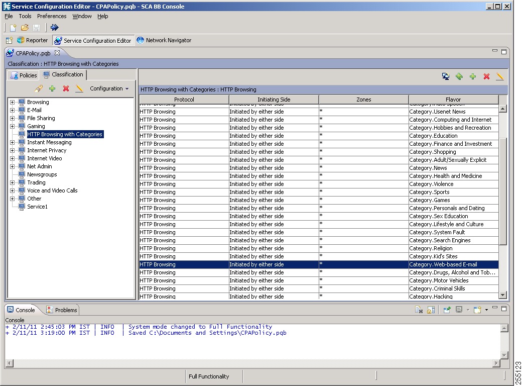
Note ![]() To view this new service, you must save and close the service configuration and then reopen it.
To view this new service, you must save and close the service configuration and then reopen it.
How to Import Content Filtering Categories Using the Import Dialog Box
You can import content filtering categories using either the File > Import menu option or the Configuration > Classification > Content Filtering menu option.
This procedure explains how to import using the File > Import menu option.
Note ![]() This is equivalent to the following procedure.
This is equivalent to the following procedure.
Step 1 ![]() From the Console main menu, choose File > Import.
From the Console main menu, choose File > Import.
The Import dialog box appears (Figure 7-55).
Figure 7-55 Import
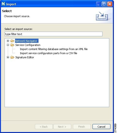
Step 2 ![]() From the import source list, select Import content filtering database settings from an XML file.
From the import source list, select Import content filtering database settings from an XML file.
Step 3 ![]() Click Next.
Click Next.
The Import Content Filtering Database Settings dialog box appears (Figure 7-56).
Figure 7-56 Import Content Filtering Database Settings
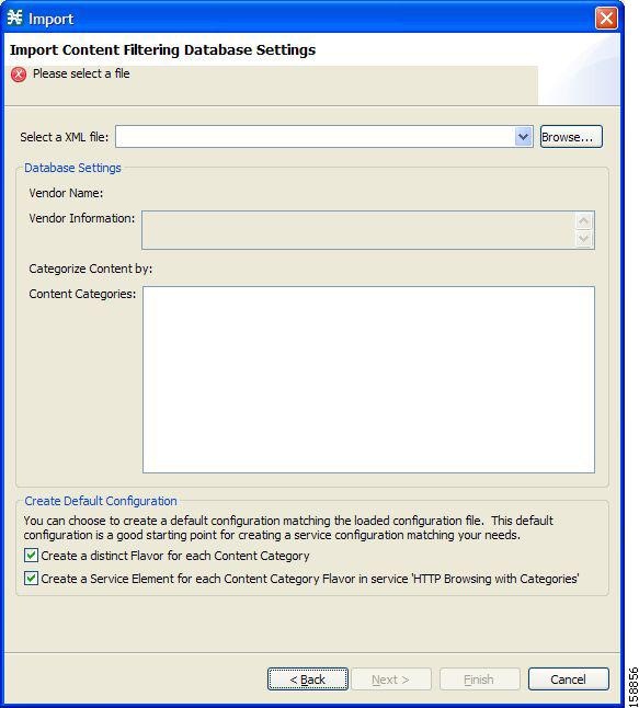
Step 4 ![]() Click the Browse button next to the Select an XML file field.
Click the Browse button next to the Select an XML file field.
An Open dialog box appears.
Step 5 ![]() Browse to the folder containing the file to import, and select it.
Browse to the folder containing the file to import, and select it.
Note ![]() For CPAof SurfControl, the file is named surfcontrol.xml.
For CPAof SurfControl, the file is named surfcontrol.xml.
Step 6 ![]() Click Open to select the file.
Click Open to select the file.
The Open dialog box closes.
Information about the content of the XML file is displayed in the Database Settings pane of the Import Content Filtering Database Settings dialog box.
Step 7 ![]() By default, Cisco SCA BB creates a separate flavor (of type HTTP Content Category) for each content category when importing the XML file.
By default, Cisco SCA BB creates a separate flavor (of type HTTP Content Category) for each content category when importing the XML file.
•![]() To disable this option, uncheck the Create a distinct Flavor for each Content Category check box.
To disable this option, uncheck the Create a distinct Flavor for each Content Category check box.
Note ![]() It is recommended that you do not disable this option.
It is recommended that you do not disable this option.
Step 8 ![]() By default, Cisco SCA BB creates a service element for each flavor created in the previous Step. A new top-level service, HTTP Browsing with Categories, is created, comprising these service elements.
By default, Cisco SCA BB creates a service element for each flavor created in the previous Step. A new top-level service, HTTP Browsing with Categories, is created, comprising these service elements.
•![]() To disable this option, uncheck the Create a Service Element for each Content Category Flavor in Service `HTTP Browsing with Categories' check box.
To disable this option, uncheck the Create a Service Element for each Content Category Flavor in Service `HTTP Browsing with Categories' check box.
Note ![]() It is recommended that you do not disable this option.
It is recommended that you do not disable this option.
Step 9 ![]() Click Finish.
Click Finish.
The Import Content Filtering Database Settings dialog box closes.
Information from the imported file is displayed in the Database Settings tab of the HTTP Content Filtering Settings dialog box (Figure 7-57).
Figure 7-57 HTTP Content Filtering Settings
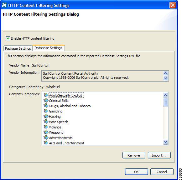
Step 10 ![]() Click OK.
Click OK.
The HTTP Content Filtering Settings dialog box closes.
How to Import Content Filtering Categories Using the HTTP Content Filtering Settings Dialog Box
You can import content filtering categories using either the File > Import menu option or the Configuration > Classification > Content Filtering menu option.
This procedure explains how to import using the Configuration > Classification > Content Filtering menu option.
Note ![]() This is equivalent to the How to Import Content Filtering Categories Using the Import Dialog Box procedure.
This is equivalent to the How to Import Content Filtering Categories Using the Import Dialog Box procedure.
Step 1 ![]() From the Classification tab in the left pane, choose Configuration > Classification > Content Filtering.
From the Classification tab in the left pane, choose Configuration > Classification > Content Filtering.
The HTTP Content Filtering Settings dialog box appears.
Step 2 ![]() Click the Database Settings tab.
Click the Database Settings tab.
The Database Settings tab opens.
Step 3 ![]() Click Import.
Click Import.
The Import Content Filtering Database Settings dialog box appears.
Step 4 ![]() Click the Browse button next to the Select an XML file field.
Click the Browse button next to the Select an XML file field.
An Open dialog box appears.
Step 5 ![]() Browse to the folder containing the file to import, and select it.
Browse to the folder containing the file to import, and select it.
Note ![]() For the CPA of SurfControl, the file is named surfcontrol.xml.
For the CPA of SurfControl, the file is named surfcontrol.xml.
Step 6 ![]() Click Open to select the file.
Click Open to select the file.
The Open dialog box closes.
Information about the content of the XML file is displayed in the Database Settings pane of the Import Content Filtering Database Settings dialog box.
Step 7 ![]() By default, Cisco SCA BB creates a separate flavor (of type HTTP Content Category) for each content category when importing the XML file.
By default, Cisco SCA BB creates a separate flavor (of type HTTP Content Category) for each content category when importing the XML file.
•![]() To disable this option, uncheck the Create a distinct Flavor for each Content Category check box.
To disable this option, uncheck the Create a distinct Flavor for each Content Category check box.
Note ![]() It is recommended that you do not disable this option.
It is recommended that you do not disable this option.
Step 8 ![]() By default, Cisco SCA BB creates a service element for each flavor created in the previous Step. A new top-level service, HTTP Browsing with Categories, is created, comprising these service elements.
By default, Cisco SCA BB creates a service element for each flavor created in the previous Step. A new top-level service, HTTP Browsing with Categories, is created, comprising these service elements.
•![]() To disable this option, uncheck the Create a Service Element for each Content Category Flavor in Service `HTTP Browsing with Categories' check box.
To disable this option, uncheck the Create a Service Element for each Content Category Flavor in Service `HTTP Browsing with Categories' check box.
Note ![]() It is recommended that you do not disable this option.
It is recommended that you do not disable this option.
Step 9 ![]() Click Finish.
Click Finish.
The Import Content Filtering Database Settings dialog box closes.
Information from the imported file is displayed in the Database Settings tab of the HTTP Content Filtering Settings dialog box (Figure 7-58).
Figure 7-58 HTTP Content Filtering Settings
Step 10 ![]() Click OK.
Click OK.
The HTTP Content Filtering Settings dialog box closes.
How to Enable Content Filtering
You can specify the packages where content filtering is enabled. For packages where content filtering is disabled, HTTP flows are classified normally.
To configure content filtering, complete the following steps:
Step 1 ![]() From the Classification tab in the left pane, choose Configuration > Classification > Content Filtering.
From the Classification tab in the left pane, choose Configuration > Classification > Content Filtering.
The HTTP Content Filtering Settings dialog box appears (Figure 7-59).
The Package Settings tab displays a list of all packages defined for the current service configuration.
Figure 7-59 HTTP Content Filtering Settings
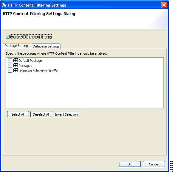
Step 2 ![]() Check the Enable HTTP content filtering check box.
Check the Enable HTTP content filtering check box.
Step 3 ![]() Check the check box next to each package for which content filtering is to be applied.
Check the check box next to each package for which content filtering is to be applied.
Step 4 ![]() Click OK.
Click OK.
The HTTP Content Filtering Settings dialog box closes.
How to View Content Filtering Settings
You can view whether content filtering is enabled and to which packages content filtering is applied, and information about the content filtering vendor and the content categories of the vendor.
Step 1 ![]() From the Classification tab in the left pane, choose Configuration > Classification > Content Filtering.
From the Classification tab in the left pane, choose Configuration > Classification > Content Filtering.
The HTTP Content Filtering Settings dialog box appears.
The Package Settings tab displays a list of all packages defined for the current service configuration, and shows for which packages content filtering is enabled.
Step 2 ![]() Click the Database Settings tab.
Click the Database Settings tab.
The Database Settings tab opens.
This tab displays information about the content filtering vendor and the content categories of the vendor.
Step 3 ![]() Click OK.
Click OK.
The HTTP Content Filtering Settings dialog box closes.
How to Configure Content Filtering
While configuring Content Filtering, you must enter the ClickStream-New Page and ClickStream-New Site services along with HTTP Browsing protocol services for optimal HTTP content filtering.
The term ClickStream refers to all events generated by user clicks, including enter. If configured, Cisco SCE identifies the HTTP transactions on the flows that were initialized due to direct user actions such as click on a link, enter a URL in the browser address bar and press enter.
To configure Content Filtering, complete the following steps:
Step 1 ![]() Open Cisco SCA BB Service Configuration Editor with the default content filtering file (PQB).
Open Cisco SCA BB Service Configuration Editor with the default content filtering file (PQB).
Step 2 ![]() Add a new service Service1.
Add a new service Service1.
Step 3 ![]() Verify that you do not have duplicate service elements. Cisco SCA BB does not allow duplicate service elements.
Verify that you do not have duplicate service elements. Cisco SCA BB does not allow duplicate service elements.
Step 4 ![]() Move the desired service element from HTTP Browsing with Categories to Service1.
Move the desired service element from HTTP Browsing with Categories to Service1.
Step 5 ![]() In Service1, add a service element using protocol ClickStream-New Page and with the same Flavor selected in Step 4.
In Service1, add a service element using protocol ClickStream-New Page and with the same Flavor selected in Step 4.
Step 6 ![]() In Service1, add a service element using protocol ClickStream-New Site and with the same Flavor selected in Step 4.
In Service1, add a service element using protocol ClickStream-New Site and with the same Flavor selected in Step 4.
Step 7 ![]() Save the service configuration file (PQB).
Save the service configuration file (PQB).
Step 8 ![]() Use the service to create rules in the desired package.
Use the service to create rules in the desired package.
Example: Configuring Content Filtering for Web Based E-mail
To configure content filtering for Web Based E-mail, complete the following steps:
Step 1 ![]() Open Cisco SCA BB Service Configuration Editor with the default content filtering file (PQB).
Open Cisco SCA BB Service Configuration Editor with the default content filtering file (PQB).
Step 2 ![]() Add a new service Service1.
Add a new service Service1.
Step 3 ![]() Move the service element Category.Web-based E-mail from HTTP Browsing with Categories to Service1.
Move the service element Category.Web-based E-mail from HTTP Browsing with Categories to Service1.
Step 4 ![]() In Service1, add a service element using protocol ClickStream-New Page and Flavor Category.Web-based E-mail.
In Service1, add a service element using protocol ClickStream-New Page and Flavor Category.Web-based E-mail.
Step 5 ![]() In Service1, add a service element using protocol ClickStream-New Site and Flavor Category.Web-based E-mail.
In Service1, add a service element using protocol ClickStream-New Site and Flavor Category.Web-based E-mail.
Step 6 ![]() Save the service configuration file (PQB) and use the service to create rules in the desired package.
Save the service configuration file (PQB) and use the service to create rules in the desired package.
How to Remove Content Filtering Settings
You can remove all content filtering settings at any time.
Removing the settings:
•![]() Removes content category flavor items from flavors
Removes content category flavor items from flavors
•![]() Deletes all the content category flavor items
Deletes all the content category flavor items
•![]() Disables content filtering
Disables content filtering
Step 1 ![]() From the Classification tab in the left pane, choose Configuration > Classification > Content Filtering.
From the Classification tab in the left pane, choose Configuration > Classification > Content Filtering.
The HTTP Content Filtering Settings dialog box appears.
Step 2 ![]() Click the Database Settings tab.
Click the Database Settings tab.
The Database Settings tab opens.
Step 3 ![]() Click Remove.
Click Remove.
A Confirm Content Filtering Settings Removal dialog box appears (Figure 7-60).
Figure 7-60 Confirm Content Filtering Settings Removal
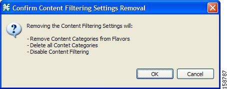
Step 4 ![]() Click OK.
Click OK.
All content filtering settings are removed.
Vendor Name, Vendor Information, and Content Categories are deleted from the HTTP Content Filtering Settings dialog box.
Step 5 ![]() Click OK.
Click OK.
The HTTP Content Filtering Settings dialog box closes.
•![]() Generic Protocols—Generic IP, Generic TCP, and Generic UDP protocols, used for transactions that are not specifically mapped to a protocol by any other protocol type.
Generic Protocols—Generic IP, Generic TCP, and Generic UDP protocols, used for transactions that are not specifically mapped to a protocol by any other protocol type.
•![]() IP Protocols—Protocols (such as ICMP), other than TCP and UDP protocols, identified according to the IP protocol number of the transaction.
IP Protocols—Protocols (such as ICMP), other than TCP and UDP protocols, identified according to the IP protocol number of the transaction.
•![]() Port-Based Protocols—TCP and UDP protocols, classified according to their well-known ports. The default service configuration includes more than 750 common port-based protocols.
Port-Based Protocols—TCP and UDP protocols, classified according to their well-known ports. The default service configuration includes more than 750 common port-based protocols.
•![]() Signature-Based Protocols—Protocols classified according to a Layer 7 application signature. Includes the most common protocols, such as HTTP and FTP, and a large group of popular P2P protocols.
Signature-Based Protocols—Protocols classified according to a Layer 7 application signature. Includes the most common protocols, such as HTTP and FTP, and a large group of popular P2P protocols.
•![]() P2P Protocols—Peer-to-peer file-sharing application protocols classified according to a Layer 7 application signature.
P2P Protocols—Peer-to-peer file-sharing application protocols classified according to a Layer 7 application signature.
•![]() VoIP Protocols—Voice-over-IP application protocols classified according to a Layer 7 application signature.
VoIP Protocols—Voice-over-IP application protocols classified according to a Layer 7 application signature.
•![]() SIP Protocols—Protocols classified according to a Layer 7 application signature that is SIP or has SIP characteristics.
SIP Protocols—Protocols classified according to a Layer 7 application signature that is SIP or has SIP characteristics.
•![]() Worm Protocols—Protocols classified according to a Layer 7 application signature that is based on traffic patterns of Internet worms.
Worm Protocols—Protocols classified according to a Layer 7 application signature that is based on traffic patterns of Internet worms.
•![]() Packet Stream Pattern Based Protocols—Protocols classified according to a Layer 7 application signature that is based on the pattern of the packet stream (for example, the stream's symmetry, average packet size, and rate) rather than on the packet's payload content.
Packet Stream Pattern Based Protocols—Protocols classified according to a Layer 7 application signature that is based on the pattern of the packet stream (for example, the stream's symmetry, average packet size, and rate) rather than on the packet's payload content.
•![]() Unidirectionally Detected Protocols—Protocols having a unidirectional signature.
Unidirectionally Detected Protocols—Protocols having a unidirectional signature.
Note ![]() Some protocols belong to more than one category. In particular, all predefined P2P, VoIP, SIP, Worm, and Packet Stream Pattern-Based Protocols are also defined as Signature-Based Protocols.
Some protocols belong to more than one category. In particular, all predefined P2P, VoIP, SIP, Worm, and Packet Stream Pattern-Based Protocols are also defined as Signature-Based Protocols.
Step 1 ![]() From the Classification tab in the left pane, choose Configuration > Classification > Protocols.
From the Classification tab in the left pane, choose Configuration > Classification > Protocols.
The Protocol Settings dialog box appears.
Step 2 ![]() From the drop-down list in the Protocols tab, select the type of protocol to display.
From the drop-down list in the Protocols tab, select the type of protocol to display.
The protocols of the selected type appear in the Protocols tab.
Step 3 ![]() Click Close.
Click Close.
The Protocol Settings dialog box closes.
Note ![]() The setting in the drop-down list is not saved. The next time you open the Protocol Settings dialog box, all protocols are displayed.
The setting in the drop-down list is not saved. The next time you open the Protocol Settings dialog box, all protocols are displayed.
Managing OS Fingerprinting
Cisco SCE detects the operating system (OS) used by a subscriber by using the passive OS Fingerprinting. In passive OS fingerprinting, TCP and IP header received from target host is analyzed to identify the OS.
Cisco SCE uses OS fingerprinting signatures to identify the subscriber OS. By default, Cisco SCOS contains a signature file that contains a default set of OS. Details of unknown OS may be added to the signature files using the Cisco SCA BB Console.
Cisco SCE also determines whether the subscriber is behind a NAT and whether the same subscriber is connecting using multiple OS. If multiple OS is detected for the same subscriber, Cisco SCE considers the subscriber as using a NAT.
From the Cisco SCA BB Console, you can also configure Cisco SCE to send the OS information of the subscriber in Gx messages.
Note ![]() The OS Fingerprinting feature is supported only on Cisco SCE 8000 devices.
The OS Fingerprinting feature is supported only on Cisco SCE 8000 devices.
Limitations:
•![]() OS information is available only for logged-in or active subscribers.
OS information is available only for logged-in or active subscribers.
•![]() The signature database is built based on the default settings used by various OS. If the user changes the default parameters like TCP window size through registries, it would not be possible or may lead to wrong classification of the OS.
The signature database is built based on the default settings used by various OS. If the user changes the default parameters like TCP window size through registries, it would not be possible or may lead to wrong classification of the OS.
•![]() If the subscriber has only one flow, then OS type is be detected. Subscribers that have only UDP flows are not detected
If the subscriber has only one flow, then OS type is be detected. Subscribers that have only UDP flows are not detected
•![]() If all users behind a NAT use the same OS, it will not be possible to identify NAT.
If all users behind a NAT use the same OS, it will not be possible to identify NAT.
•![]() If a subscriber runs multiple OS using VMWare, it may be detected as NAT even though the subscriber is not in a NAT environment
If a subscriber runs multiple OS using VMWare, it may be detected as NAT even though the subscriber is not in a NAT environment
•![]() OS finger printing is not done continuously for any subscriber. So, if a subscriber changes OS or moves to a NAT environment during the time when he is not sampled, OS Information and NAT cannot be detected.
OS finger printing is not done continuously for any subscriber. So, if a subscriber changes OS or moves to a NAT environment during the time when he is not sampled, OS Information and NAT cannot be detected.
Managing OS Fingerprinting
You can configure OS Fingerprinting using the Cisco SCA BB Console.
•![]() How to Enable OS Fingerprinting
How to Enable OS Fingerprinting
•![]() How to Install OS Fingerprinting Signatures
How to Install OS Fingerprinting Signatures
•![]() How to View Subscriber OS Information
How to View Subscriber OS Information
How to Enable OS Fingerprinting
Step 1 ![]() In Service Configuration Editor, select Configuration > OS Finger Print....
In Service Configuration Editor, select Configuration > OS Finger Print....
The OS Fingerprinting Settings dialog box appears (Figure 7-61).
Step 2 ![]() Check the Enable OS Finger Printing check box.
Check the Enable OS Finger Printing check box.
Figure 7-61 OS Finger Print Settings Dialog Box
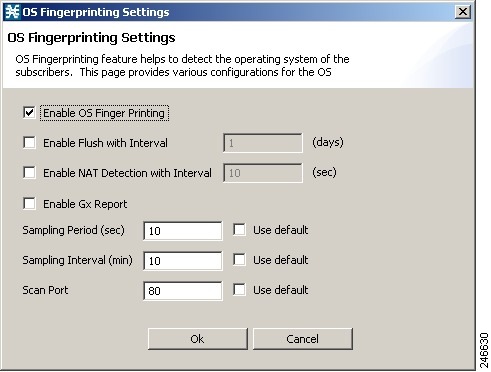
Step 3 ![]() Enable Flush with Interval—Check the Enable Flush with Interval check box and enter the interval in days to configure the interval after which the OS information will be reset.
Enable Flush with Interval—Check the Enable Flush with Interval check box and enter the interval in days to configure the interval after which the OS information will be reset.
Step 4 ![]() (Optional) Enable NAT Detection with Interval—Check the Enable NAT Detection with Interval check box and enter the interval in seconds to configure the time period with-in which multiple OS detection will trigger NAT identification. Default value is 10 seconds.
(Optional) Enable NAT Detection with Interval—Check the Enable NAT Detection with Interval check box and enter the interval in seconds to configure the time period with-in which multiple OS detection will trigger NAT identification. Default value is 10 seconds.
Step 5 ![]() (Optional) Enable Gx Report—Check the Enable Gx Report check box to enable Gx Reports.
(Optional) Enable Gx Report—Check the Enable Gx Report check box to enable Gx Reports.
Step 6 ![]() Sampling Period (sec)—Configure how long flows from a subscriber will finger-printed. Default is 10 seconds. Check the Use default check box to use the default period.
Sampling Period (sec)—Configure how long flows from a subscriber will finger-printed. Default is 10 seconds. Check the Use default check box to use the default period.
Step 7 ![]() Sampling Interval (min)—Enter the time in minutes to configure the frequency at which flows will be finger-printed. Default is 10 minutes. Check the Use default check box to use default interval.
Sampling Interval (min)—Enter the time in minutes to configure the frequency at which flows will be finger-printed. Default is 10 minutes. Check the Use default check box to use default interval.
Step 8 ![]() (Optional) Scan Port—Enter a value for Scan Port used for opening OS finger printing flows. Check the Use default check box to use the default port—port 80—for the flows. Ports 20, 21, 69, and 5060 are not allowed.
(Optional) Scan Port—Enter a value for Scan Port used for opening OS finger printing flows. Check the Use default check box to use the default port—port 80—for the flows. Ports 20, 21, 69, and 5060 are not allowed.
Step 9 ![]() Click Ok.
Click Ok.
Note ![]() After enabling OSFP in Cisco SCE using Cisco SCA BB console, enable the OSFP Reports in Cisco Service Control Collection Manager. For details on enabling the OSFP Reports in Cisco Service Control Collection Manager, see the Cisco Service Control Collection Manager User Guide.
After enabling OSFP in Cisco SCE using Cisco SCA BB console, enable the OSFP Reports in Cisco Service Control Collection Manager. For details on enabling the OSFP Reports in Cisco Service Control Collection Manager, see the Cisco Service Control Collection Manager User Guide.
How to Install OS Fingerprinting Signatures
Step 1 ![]() (Optional) Using Network Navigator, add the device on which you need to install the signatures.
(Optional) Using Network Navigator, add the device on which you need to install the signatures.
Step 2 ![]() Enable OS Fingerprinting. See the "How to Enable OS Fingerprinting" section.
Enable OS Fingerprinting. See the "How to Enable OS Fingerprinting" section.
Step 3 ![]() Apply the configuration to the device.
Apply the configuration to the device.
Step 4 ![]() In the Site Manager tree, right-click a Cisco SCE device. A popup menu appears.
In the Site Manager tree, right-click a Cisco SCE device. A popup menu appears.
Step 5 ![]() From the menu, select Install OS Finger Printing Signature....
From the menu, select Install OS Finger Printing Signature....
The Password Management dialog box appears. For details on password management, see the "Password Management" section.
Step 6 ![]() Enter the User Name and Password, and click Update.
Enter the User Name and Password, and click Update.
The Update OSFP Signature window appears.
Step 7 ![]() Enter the path to signature file in the Select OSFP Signature File field or Browse to the signature file.
Enter the path to signature file in the Select OSFP Signature File field or Browse to the signature file.
Step 8 ![]() Click Finish.
Click Finish.
A confirmation message appears in the Console.
How to View Subscriber OS Information
Step 1 ![]() Enable OS Fingerprinting. See the "How to Enable OS Fingerprinting" section.
Enable OS Fingerprinting. See the "How to Enable OS Fingerprinting" section.
Step 2 ![]() Apply the configuration to the device.
Apply the configuration to the device.
Step 3 ![]() From Subscriber Manager, view the Subscriber list. See Figure 11-6.
From Subscriber Manager, view the Subscriber list. See Figure 11-6.
Step 4 ![]() Right-click on the device, and select View Online Status.
Right-click on the device, and select View Online Status.
The online status of the subscriber appears near the console panel with the OS information. The OS Fingerprinting is available for Anonymous Groups through Anonymous Group Manager GUI Tool.
How To Disable OS Fingerprinting
Step 1 ![]() In the Service Configuration Editor, select Configuration > OS Finger Print....
In the Service Configuration Editor, select Configuration > OS Finger Print....
The OS Finger Printing Settings dialog box appears.
Step 2 ![]() Uncheck the Enable OS Finger Printing check box.
Uncheck the Enable OS Finger Printing check box.
The OS Fingerprinting CLI
Use the following CLI command in EXEC mode to monitor the OS details of the subscriber:
show os-fingerprinting subscriber-name
The following is a sample output of the command. In this example, Cisco SCE has detected a NAT and behind the NAT two OS. One is iOS with an index number 65 and another OS that is not known to Cisco SCE:
SCE8000#> show os-fingerprinting subscriber-name 192.168.0.5@testofp
Subscriber 192.168.0.5@testofp OS-Info:
IP Address:192.168.0.5
OS-INFO:
1. INDEX: 65 OS Name: iOS
UNKNOWN OS FOUND
NAT DETECTED
 Feedback