- About this Guide
- Cisco Service Control Overview
- System Overview
- Traffic Processing Overview
- Getting Started
- Using the Network Navigator
- Using the Service Configuration Editor
- Using the Service Configuration Editor: Traffic Classification
- Using the Service Configuration Editor: Traffic Accounting and Reporting
- Using the Service Configuration Editor: Traffic Control
- Using the Service Configuration Editor: Additional Options
- Using the Subscriber Manager GUI Tool
- Using the Anonymous Group Manager Tool
- Using the Signature Editor
- Additional Management Tools and Interfaces
Cisco Service Control Application for Broadband User Guide, Release 3.8.x
Bias-Free Language
The documentation set for this product strives to use bias-free language. For the purposes of this documentation set, bias-free is defined as language that does not imply discrimination based on age, disability, gender, racial identity, ethnic identity, sexual orientation, socioeconomic status, and intersectionality. Exceptions may be present in the documentation due to language that is hardcoded in the user interfaces of the product software, language used based on RFP documentation, or language that is used by a referenced third-party product. Learn more about how Cisco is using Inclusive Language.
- Updated:
- February 23, 2012
Chapter: Using the Network Navigator
- Introduction
- The Network Navigator Tool
- Managing Sites
- Managing Devices
- Password Management
- Managing Cisco SCE Devices
- How to Configure Cisco SCE and Collection Manager Devices Using a Wizard
- How to Generate Tech Support Info Files for Cisco SCE Devices
- How to Retrieve the Online Status of Cisco SCE Devices
- How to Install a Protocol Pack
- How to Apply Service Configurations to Cisco SCE Devices
- How to Retrieve Service Configurations from Cisco SCE Devices
- How to Install PQI Files on Cisco SCE Devices
- How to Install a Cisco SCE OS Software Package on Cisco SCE Devices
- Managing Subscriber Manager Devices
- Managing Collection Manager Devices
- Managing Database Devices
Using the Network Navigator
Introduction
To manage a network entity—Cisco Service Control Engine (Cisco SCE) platform, Subscriber Manager (SM), or Collection Manager (CM)—from the Console, you must first define it as a device in the Network Navigator.
This chapter describes how to use the Network Navigator tool to create a model of all local and remote sites and devices that are part of the Cisco Service Control solution, how to manage the devices remotely, and other functionality that is part of the Network Navigator tool.
The Usage Analysis wizard, which can be used to create a simple model of devices and connect to them, is also described in this chapter.
This chapter consists of these sections:
•![]() Working with Network Navigator Configuration Files
Working with Network Navigator Configuration Files
•![]() Network Settings Requirements
Network Settings Requirements
The Network Navigator Tool
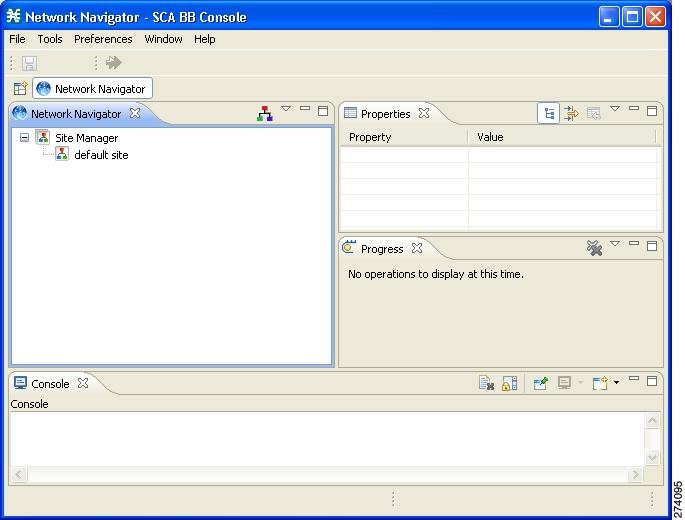
The Network Navigator tool (Figure 5-1) contains four views:
•![]() Network Navigator view—Displays all sites and devices that you have defined as part of your system, in the Site Manager tree.
Network Navigator view—Displays all sites and devices that you have defined as part of your system, in the Site Manager tree.
•![]() Properties view—Displays the editable properties of the node selected in the Site Manager tree in the Network Navigator view.
Properties view—Displays the editable properties of the node selected in the Site Manager tree in the Network Navigator view.
•![]() Progress view—Displays a progress bar when you perform an operation on a site or device in the Site Manager tree.
Progress view—Displays a progress bar when you perform an operation on a site or device in the Site Manager tree.
•![]() Console view—Displays log messages concerning actions performed in the Network Navigator tool.
Console view—Displays log messages concerning actions performed in the Network Navigator tool.
Figure 5-1 The Network Navigator Tool
Managing Sites
You can manage a Cisco SCE, Subscriber Manager, or CM from the Console only if the network entity is defined as a device in the Network Navigator. After a device is added to the Network Navigator, you can perform management and monitoring operations on the device.
You can also perform operations on a group of devices. For example, you can apply the same service configuration to a group of Cisco SCE platforms. The Network Navigator enables you to group devices by adding them under the same site. A site is a group of devices that can be managed together. At installation, the Network Navigator contains a default site with no devices. You can add devices to this site or add additional sites, as described in the following sections.
Grouping devices in sites can also help to manage the passwords for these devices (see "Password Management" section).
This section explains these procedures:
•![]() How to Add a Site to the Site Manager
How to Add a Site to the Site Manager
How to Add a Site to the Site Manager
Before adding devices, you must add your sites to the Site Manager. To add a device to a site, complete these steps:
Step 1 ![]() In the Network Navigator view, right-click the Site Manager node.
In the Network Navigator view, right-click the Site Manager node.
A popup menu appears (Figure 5-2).
Figure 5-2 Site Manager Menu
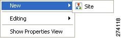
Step 2 ![]() From the menu, select New > Site.
From the menu, select New > Site.
A new Site node is added to the Site Manager.
Step 3 ![]() In the Properties view, enter a name for the site in the Name cell.
In the Properties view, enter a name for the site in the Name cell.
Step 4 ![]() (Optional) In the Version cell, enter a version number.
(Optional) In the Version cell, enter a version number.
How to Add Devices to a Site
You can add Cisco SCE, Subscriber Manager, CM, or database devices to a site.
•![]() How to Add Cisco SCE Devices to a Site
How to Add Cisco SCE Devices to a Site
•![]() How to Add Subscriber Manager Devices to a Site
How to Add Subscriber Manager Devices to a Site
•![]() How to Add Collection Manager Devices to a Site
How to Add Collection Manager Devices to a Site
•![]() How to Add Database Devices to a Site
How to Add Database Devices to a Site
How to Add Cisco SCE Devices to a Site
To use the Network Navigator to configure, monitor, and update the software of a Cisco SCE platform, you must first add the Cisco SCE platform to a site.
Step 1 ![]() In the Site Manager tree, right-click a site.
In the Site Manager tree, right-click a site.
A popup menu appears (Figure 5-3).
Figure 5-3 Site Manager Tree Menu
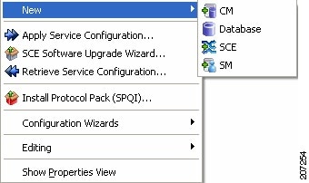
Step 2 ![]() From the menu, select New > SCE.
From the menu, select New > SCE.
The Create New SCE wizard appears.
Step 3 ![]() In the Address field, enter the IP address of the Cisco SCE.
In the Address field, enter the IP address of the Cisco SCE.
Step 4 ![]() (Optional) In the Name field, enter a meaningful name for the Cisco SCE.
(Optional) In the Name field, enter a meaningful name for the Cisco SCE.
Step 5 ![]() Click Finish.
Click Finish.
The Create New SCE wizard closes.
The new device is added to the site.
How to Add Subscriber Manager Devices to a Site
To use the Network Navigator to configure, monitor, and update the software of an Subscriber Manager, you must first add the Subscriber Manager to a site.
Step 1 ![]() In the Site Manager tree, right-click a site.
In the Site Manager tree, right-click a site.
A popup menu appears.
Step 2 ![]() From the menu, select New > SM.
From the menu, select New > SM.
The Create New SM wizard appears.
Step 3 ![]() In the Address field, enter the IP address of the SCMS Subscriber Manager.
In the Address field, enter the IP address of the SCMS Subscriber Manager.
Step 4 ![]() (Optional) In the Name field, enter a meaningful name for the Subscriber Manager.
(Optional) In the Name field, enter a meaningful name for the Subscriber Manager.
Step 5 ![]() Click Finish.
Click Finish.
The Create New SM wizard closes.
The new device is added to the site.
How to Add Collection Manager Devices to a Site
To use the Network Navigator to monitor a Collection Manager, you must first add the Collection Manager to a site.
Step 1 ![]() In the Site Manager tree, right-click a site.
In the Site Manager tree, right-click a site.
A popup menu appears.
Step 2 ![]() From the menu, select New > CM.
From the menu, select New > CM.
The Create New CM wizard appears.
Step 3 ![]() In the Address field, enter the IP address of the Collection Manager.
In the Address field, enter the IP address of the Collection Manager.
Step 4 ![]() (Optional) In the Name field, enter a meaningful name for the Collection Manager.
(Optional) In the Name field, enter a meaningful name for the Collection Manager.
Step 5 ![]() Click Finish.
Click Finish.
The Create New CM wizard closes.
The new device is added to the site.
How to Add Database Devices to a Site
To use the Reporter tool to produce reports, you must first connect to a database.
Step 1 ![]() In the Site Manager tree, right-click a site.
In the Site Manager tree, right-click a site.
A popup menu appears.
Step 2 ![]() From the menu, select New > Database.
From the menu, select New > Database.
The Create New Database wizard appears (Figure 5-4).
Figure 5-4 Create New Database
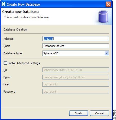
Step 3 ![]() In the Address field, enter the IP address of the database.
In the Address field, enter the IP address of the database.
Step 4 ![]() (Optional) In the Name field, enter a meaningful name for the database.
(Optional) In the Name field, enter a meaningful name for the database.
Step 5 ![]() From the Database type drop-down list, select a database type.
From the Database type drop-down list, select a database type.
Step 6 ![]() (Optional) Check the Enable Advanced Settings check box and enter new values in the Url, Driver, User, and Password fields.
(Optional) Check the Enable Advanced Settings check box and enter new values in the Url, Driver, User, and Password fields.
Step 7 ![]() Click Finish.
Click Finish.
The Create New Database wizard closes.
The new device is added to the site.
How to Delete Devices
Step 1 ![]() In the Site Manager tree, right-click a device.
In the Site Manager tree, right-click a device.
A popup menu appears.
Step 2 ![]() From the menu, select Delete.
From the menu, select Delete.
The device is deleted and removed from the Site Manager tree.
How to Delete Sites
Step 1 ![]() In the Site Manager tree, right-click a site in the Site Manager tree.
In the Site Manager tree, right-click a site in the Site Manager tree.
A popup menu appears.
•![]() Enter your password if prompted.
Enter your password if prompted.
Step 2 ![]() From the menu, select Delete.
From the menu, select Delete.
The site and all its devices are deleted and the site is removed from the Site Manager tree.
Managing Devices
The Network Navigator enables you to manage Cisco SCE, Cisco Service Control Subscriber Manager, Cisco Service Control Collection Manager, and database devices.

Note ![]() The Usage Analysis wizard enables you to create a simple model of devices and connect to those devices to perform various tasks. (See "How to Use the Usage Analysis Wizard" section.)
The Usage Analysis wizard enables you to create a simple model of devices and connect to those devices to perform various tasks. (See "How to Use the Usage Analysis Wizard" section.)
This section contains these topics:
•![]() Managing Subscriber Manager Devices
Managing Subscriber Manager Devices
•![]() Managing Collection Manager Devices
Managing Collection Manager Devices
Password Management
Normally, before you can access a device (Cisco SCE, Cisco Service Control Subscriber Manager, Cisco Service Control Collection Manager, or database), you must enter its password. When you try to perform any operation on a site device, the Network Navigator first asks for the device username and password. (Repeating the same operation on the same device does not always require a second entry of the password.)
When performing operations on multiple devices, password entry can become tedious. The Site Master Password can help you remember some or all usernames and passwords of your element by storing them as part of the site data, and entering them for you automatically when you connect to an element.
The Site Master Password protects saved usernames and passwords in the password manager. The Password Management dialog box (Figure 5-5) prompts you for the master password of the site when you wish to activate the site password manager. If you have multiple sites, each site requires a separate master password.
Figure 5-5 The Password Management Dialog Box
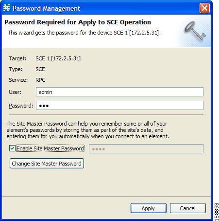
For each site, when the Password Management dialog box appears, check the Enable Site Master Password check box.
Managing Cisco SCE Devices
This section explains the following procedures:
•![]() How to Configure Cisco SCE and Collection Manager Devices Using a Wizard
How to Configure Cisco SCE and Collection Manager Devices Using a Wizard
•![]() How to Generate Tech Support Info Files for Cisco SCE Devices
How to Generate Tech Support Info Files for Cisco SCE Devices
•![]() How to Retrieve the Online Status of Cisco SCE Devices
How to Retrieve the Online Status of Cisco SCE Devices
•![]() How to Install a Protocol Pack
How to Install a Protocol Pack
•![]() How to Apply Service Configurations to Cisco SCE Devices
How to Apply Service Configurations to Cisco SCE Devices
•![]() How to Retrieve Service Configurations from Cisco SCE Devices
How to Retrieve Service Configurations from Cisco SCE Devices
•![]() How to Install PQI Files on Cisco SCE Devices
How to Install PQI Files on Cisco SCE Devices
•![]() How to Install a Cisco SCE OS Software Package on Cisco SCE Devices
How to Install a Cisco SCE OS Software Package on Cisco SCE Devices
How to Configure Cisco SCE and Collection Manager Devices Using a Wizard
The Network Navigator Device wizard allows you to configure Cisco SCE and Cisco Service Control Collection Manager devices and connect to them.
Note ![]() If they do not exist, devices defined in the wizard are added to the default site in the Site Manager tree.
If they do not exist, devices defined in the wizard are added to the default site in the Site Manager tree.
Step 1 ![]() In the Network Navigator view toolbar, click the Configure SCE and CM devices (
In the Network Navigator view toolbar, click the Configure SCE and CM devices ( ) icon.
The Welcome window of the Network Navigator Device wizard appears (Figure 5-6).
Figure 5-6 Welcome - Network Navigator Device
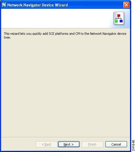
Step 2 ![]() Click Next.
Click Next.
The SCE IP Addresses page of the Network Navigator Device wizard opens (Figure 5-7).
Figure 5-7 SCE IP Addresses
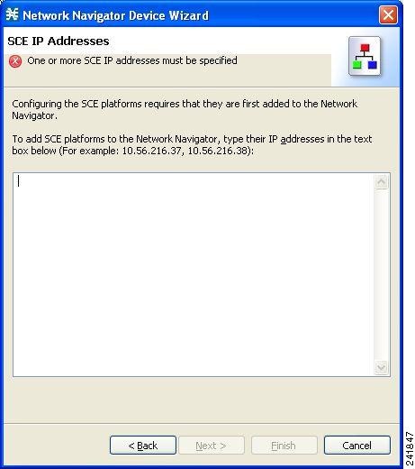
Step 3 ![]() In the edit box, enter the IP addresses of the Cisco SCE devices that should be added to the model.
In the edit box, enter the IP addresses of the Cisco SCE devices that should be added to the model.
If you started from the Network Navigator, the IP addresses of the Cisco SCE devices that you selected are displayed in the edit box. You can add additional addresses.
Note ![]() You can work with up to 20 Cisco SCE devices at one time using the wizard.
You can work with up to 20 Cisco SCE devices at one time using the wizard.
Step 4 ![]() Click Next.
Click Next.
The SCE Usernames and Passwords page of the Network Navigator Device wizard opens (Figure 5-8).
Figure 5-8 SCE Usernames and Passwords
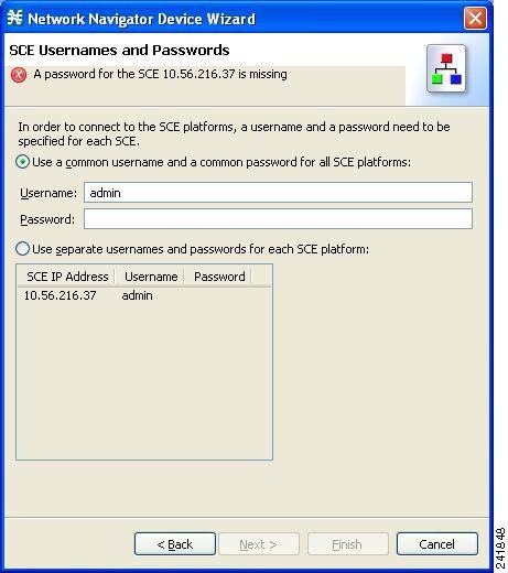
Step 5 ![]() Enter the usernames and passwords for the Cisco SCE devices.
Enter the usernames and passwords for the Cisco SCE devices.
Do one of the following:
•![]() To use the same username and password for all the Cisco SCE devices that you are adding, enter the username in the Username field and the password in the Password field.
To use the same username and password for all the Cisco SCE devices that you are adding, enter the username in the Username field and the password in the Password field.
•![]() To provide a different username and password pair for each Cisco SCE device, check the Use separate usernames and passwords for each SCE device radio button, and, for each Cisco SCE device, enter the username and password in the appropriate cell of the Cisco SCE device table.
To provide a different username and password pair for each Cisco SCE device, check the Use separate usernames and passwords for each SCE device radio button, and, for each Cisco SCE device, enter the username and password in the appropriate cell of the Cisco SCE device table.
Step 6 ![]() Click Next.
Click Next.
The CM Setup page of the Network Navigator Device wizard opens (Figure 5-9).
Figure 5-9 CM Setup
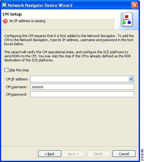
Step 7 ![]() Define the SCMS Collection Manager to use with this configuration.
Define the SCMS Collection Manager to use with this configuration.
Do one of the following:
•![]() Enter the IP address, username, and password of the CM device in the appropriate fields.
Enter the IP address, username, and password of the CM device in the appropriate fields.
If you started from the Network Navigator, this information is retrieved and displayed. You can modify these parameters.
•![]() Check the Skip this step check box.
Check the Skip this step check box.
Step 8 ![]() Click Next.
Click Next.
The Connectivity Test page of the Network Navigator Device wizard opens (Figure 5-10).
Figure 5-10 Connectivity Test
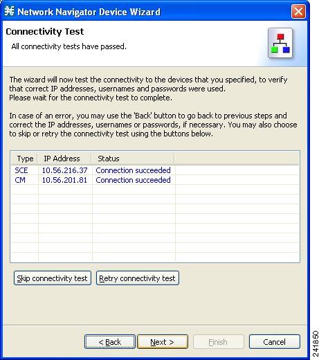
The wizard tests to see that the connections to the defined devices can be made.
Note ![]() If a connection to one or more of the devices cannot be made or if there is some problem with the connection (such as invalid version of the device) an error is displayed next to the device. You can skip these tests by clicking Skip Connections. The connections are validated when you click Finish at the end of the wizard.
If a connection to one or more of the devices cannot be made or if there is some problem with the connection (such as invalid version of the device) an error is displayed next to the device. You can skip these tests by clicking Skip Connections. The connections are validated when you click Finish at the end of the wizard.
Step 9 ![]() Click Next.
Click Next.
The Confirmation page of the Network Navigator Device wizard opens (Figure 5-11).
Figure 5-11 Confirmation
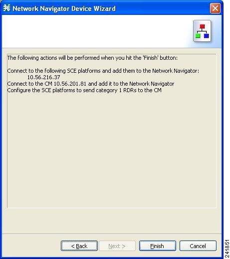
The actions that the wizard is about to take are listed on the page.
Step 10 ![]() Click Finish.
Click Finish.
The Configuration Output page of the Network Navigator Device wizard opens (Figure 5-12).
Figure 5-12 Configuration Output
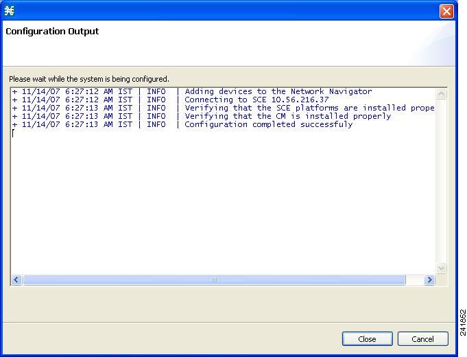
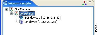
New devices are added to the default site in the Site Manager tree in the Network Navigator (Figure 5-13).
Figure 5-13 Network Navigator
The wizard attempts to connect to all devices that you defined. The operation fails if:
•![]() The wizard cannot connect to any of the Cisco SCE devices that you listed in Step 3.
The wizard cannot connect to any of the Cisco SCE devices that you listed in Step 3.
•![]() You defined a CM in Step 7, but the wizard cannot connect to it.
You defined a CM in Step 7, but the wizard cannot connect to it.
If you defined a CM in Step 7, the Cisco SCE devices are configured so that the only category 1 RDR destination is the CM.
Note ![]() RDR categories are the mechanism by which different types of RDRs can be sent to different collectors. For more information about RDR categories, see either the "Raw Data Formatting: The RDR Formatter and NetFlow Exporting" chapter of Cisco SCE8000 10GBE Software Configuration Guide or the "Raw Data Formatting: The RDR Formatter and NetFlow Exporting" chapter of Cisco SCE8000 GBE Software Configuration Guide.
RDR categories are the mechanism by which different types of RDRs can be sent to different collectors. For more information about RDR categories, see either the "Raw Data Formatting: The RDR Formatter and NetFlow Exporting" chapter of Cisco SCE8000 10GBE Software Configuration Guide or the "Raw Data Formatting: The RDR Formatter and NetFlow Exporting" chapter of Cisco SCE8000 GBE Software Configuration Guide.
A new service configuration is created:
•![]() Report Only mode.
Report Only mode.
•![]() The maximum Transaction RDR rate is set as the default value (250) divided by the number of Cisco SCE devices. (To configure the Transaction RDR, see "How to Manage Transaction RDRs" section; the content and structure of the Transaction RDR is listed in the "Transaction RDR" section in the "Raw Data Records: Formats and Field Contents" chapter of Cisco Service Control Application for Broadband Reference Guide.)
The maximum Transaction RDR rate is set as the default value (250) divided by the number of Cisco SCE devices. (To configure the Transaction RDR, see "How to Manage Transaction RDRs" section; the content and structure of the Transaction RDR is listed in the "Transaction RDR" section in the "Raw Data Records: Formats and Field Contents" chapter of Cisco Service Control Application for Broadband Reference Guide.)
Step 11 ![]() Click Finish.
Click Finish.
The Network Navigator Device wizard closes.
How to Generate Tech Support Info Files for Cisco SCE Devices
This operation generates the support file, for the Cisco SCE platform, for the use of Cisco technical support staff.
Step 1 ![]() In the Site Manager tree, right-click an SCE device.
In the Site Manager tree, right-click an SCE device.
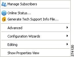
A popup menu appears (Figure 5-14).
Figure 5-14 Site Manager Tree Menu
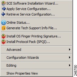
Step 2 ![]() From the menu, select Generate Tech Support Info File.
From the menu, select Generate Tech Support Info File.
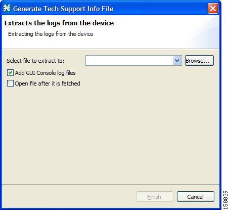
The Generate Tech Support Info File dialog box appears (Figure 5-15).
Figure 5-15 Generate Tech Support Info File
Step 3 ![]() Click Browse.
Click Browse.
A Select File dialog box appears.
Step 4 ![]() Browse to the folder where you want to save the tech support info file.
Browse to the folder where you want to save the tech support info file.
Step 5 ![]() In the File name field, enter a new file name, or select an existing ZIP file.
In the File name field, enter a new file name, or select an existing ZIP file.
Step 6 ![]() Click Open to select the file.
Click Open to select the file.
If the file exists, it is overwritten when you generate the tech support info.
The Select File dialog box closes.
Step 7 ![]() (Optional) To add log files to the output tech support info file, check the Add GUI Console log files check box.
(Optional) To add log files to the output tech support info file, check the Add GUI Console log files check box.
Step 8 ![]() (Optional) Check the Open file after it is fetched check box.
(Optional) Check the Open file after it is fetched check box.
Step 9 ![]() Click Finish.
Click Finish.
The Generate Tech Support Info File dialog box closes.
A Password Management dialog box appears.
Step 10 ![]() Enter the appropriate password. (For more information, see "Password Management" section.)
Enter the appropriate password. (For more information, see "Password Management" section.)
Step 11 ![]() Click Generate.
Click Generate.
The Password Management dialog box closes.
A Generate tech support info file progress bar appears.
The file is generated.
How to Retrieve the Online Status of Cisco SCE Devices
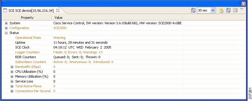
This operation provides information about the current software version and operational status of the Cisco SCE platform. The enhanced Cisco SCE online statuses are categorized as:
•![]() System—displays the platform information
System—displays the platform information
•![]() Configuration—displays the Hostname
Configuration—displays the Hostname
•![]() Status—displays the operational mode and total traffic on the Cisco SCE
Status—displays the operational mode and total traffic on the Cisco SCE
For more information on monitoring Cisco SCE online status, see the Cisco SCA BB Demo Kit Quick Start Guide.
Step 1 ![]() In the Site Manager tree, right-click an SCE device.
In the Site Manager tree, right-click an SCE device.
A popup menu appears.
Step 2 ![]() From the menu, select Online Status.
From the menu, select Online Status.
A Password Management dialog box appears.
Step 3 ![]() Enter the appropriate password. (For more information, see "Password Management" section.)
Enter the appropriate password. (For more information, see "Password Management" section.)
Step 4 ![]() Enter the SNMP RO Community String.
Enter the SNMP RO Community String.
If SNMP is not already enabled on the Cisco SCE, it gets enabled.
If RO communities are not configured on the Cisco SCE or if only RW communities are configured on the Cisco SCE, the SNMP RO community you provide here is added to the Cisco SCE.
If only RO communities are configured on the Cisco SCE, the SNMP RO community you provide here is validated first against the RO communities configured on Cisco SCE. If the RO community is valid, the online status window is launched. If the RO community is not valid, a validation message appears.
Step 5 ![]() Click Extract.
Click Extract.
The Password Management dialog box closes.
An Extracting info progress bar appears.
The Cisco SCE online status is retrieved (Figure 5-16).
Figure 5-16 Cisco SCE Online Status
How to Install a Protocol Pack
You can install a protocol pack on a single Cisco SCE platform, on selected Cisco SCE platforms, or on all Cisco SCE platforms at one or more selected sites. For more information about protocol packs, see "Working with Protocol Packs" section.
Note ![]() Cisco recommends the use of Cisco SCE Software Upgrade wizard when installing a protocol pack on multiple Cisco SCE platforms.
Cisco recommends the use of Cisco SCE Software Upgrade wizard when installing a protocol pack on multiple Cisco SCE platforms.
This section explains these procedures:
•![]() How to Install a Protocol Pack on a Single Cisco SCE Platform
How to Install a Protocol Pack on a Single Cisco SCE Platform
•![]() How to Install a Protocol Pack on Multiple Cisco SCE Platforms
How to Install a Protocol Pack on Multiple Cisco SCE Platforms
How to Install a Protocol Pack on a Single Cisco SCE Platform
Step 1 ![]() In the Site Manager tree, right-click the Cisco SCE on which you plan to install the protocol pack.
In the Site Manager tree, right-click the Cisco SCE on which you plan to install the protocol pack.
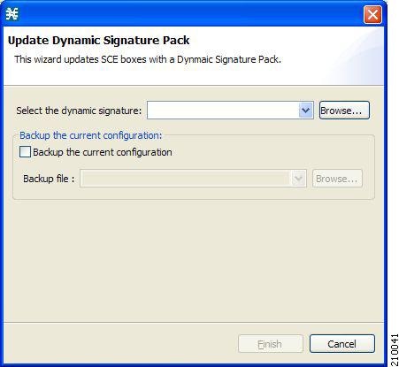
Step 2 ![]() From the popup menu that appears, select Update Dynamic Signature Pack.
From the popup menu that appears, select Update Dynamic Signature Pack.
The Update Dynamic Signature Pack dialog box appears (Figure 5-17).
Figure 5-17 Update Dynamic Signature Pack
Step 3 ![]() Click Browse.
Click Browse.
A Select file dialog box appears.
Step 4 ![]() From the Files of type drop-down list, select *.spqi or *.dss, depending on the file to be installed.
From the Files of type drop-down list, select *.spqi or *.dss, depending on the file to be installed.
Step 5 ![]() Browse to the file to be installed.
Browse to the file to be installed.
Step 6 ![]() Click Open.
Click Open.
The Select file dialog box closes.
Step 7 ![]() (Recommended) Check the Backup the current configuration check box, click Browse, and select a backup file.
(Recommended) Check the Backup the current configuration check box, click Browse, and select a backup file.
Step 8 ![]() Click Finish.
Click Finish.
A Password Management dialog box appears.
Step 9 ![]() Enter the appropriate password.
Enter the appropriate password.
For more information, see "Password Management" section.
Step 10 ![]() Click Update.
Click Update.
The Password Management dialog box closes.
An Update Dynamic Signature Pack progress bar appears.
The service configuration on the Cisco SCE platform is updated.
How to Install a Protocol Pack on Multiple Cisco SCE Platforms
You can install a protocol pack on multiple Cisco SCE Platforms using the SCE Software Upgrade wizard. See "How to Upgrade the SCE Using the SCE Software Upgrade Wizard" section.
How to Apply Service Configurations to Cisco SCE Devices
You can apply a service configuration to a single Cisco SCE platform, to selected Cisco SCE platforms, or to all Cisco SCE platforms at one or more selected sites.
Note ![]() The service configuration that you are applying must be open in the Service Configuration Editor.
The service configuration that you are applying must be open in the Service Configuration Editor.

Workaround:
Disable anomaly-based detection of malicious traffic.
In the Network Traffic tab, select Service Security.
In the Service Security Dashboard, clear the Enable anomaly detection check box.
•![]() How to Apply a Service Configuration to a Single Cisco SCE Platform
How to Apply a Service Configuration to a Single Cisco SCE Platform
•![]() How to Apply a Service Configuration to Multiple Cisco SCE Platforms
How to Apply a Service Configuration to Multiple Cisco SCE Platforms
How to Apply a Service Configuration to a Single Cisco SCE Platform
Step 1 ![]() In the Site Manager tree, right-click a Cisco SCE device.
In the Site Manager tree, right-click a Cisco SCE device.
A popup menu appears.
Step 2 ![]() From the menu, select Apply Service Configuration.
From the menu, select Apply Service Configuration.
The Choose Policy dialog box appears (Figure 5-18), listing all service configurations that are open in the Service Configuration Editor.
Note ![]() If only one service configuration is open in the Service Configuration Editor, a Password Management dialog box appears. Continue at Step 5. (If no service configurations are open in the Service Configuration Editor, an error message is displayed.)
If only one service configuration is open in the Service Configuration Editor, a Password Management dialog box appears. Continue at Step 5. (If no service configurations are open in the Service Configuration Editor, an error message is displayed.)
Figure 5-18 Choose Policy
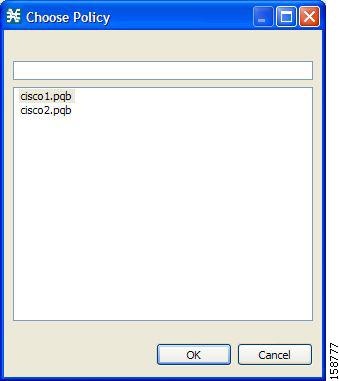
Step 3 ![]() Select a service configuration from the list.
Select a service configuration from the list.
Step 4 ![]() Click OK.
Click OK.
A Password Management dialog box appears.
Step 5 ![]() Enter the appropriate password. (For more information, see "Password Management" section.)
Enter the appropriate password. (For more information, see "Password Management" section.)
Step 6 ![]() Click Apply.
Click Apply.
The Password Management dialog box closes.
An Applying service configuration to Cisco SCE progress bar appears.
The service configuration is applied to the selected Cisco SCE platform.
How to Apply a Service Configuration to Multiple Cisco SCE Platforms
Step 1 ![]() In the Site Manager tree, select sites or Cisco SCE devices to which you are applying the service configuration and right-click one of them.
In the Site Manager tree, select sites or Cisco SCE devices to which you are applying the service configuration and right-click one of them.
Step 2 ![]() From the popup menu that appears, select Apply Service Configuration.
From the popup menu that appears, select Apply Service Configuration.
The Choose Policy dialog box appears, listing all service configurations that are open in the Service Configuration Editor.
Note ![]() If only one service configuration is open in the Service Configuration Editor, a Password Management dialog box appears. Continue at Step 4. (If no service configurations are open in the Service Configuration Editor, an error message is displayed.)
If only one service configuration is open in the Service Configuration Editor, a Password Management dialog box appears. Continue at Step 4. (If no service configurations are open in the Service Configuration Editor, an error message is displayed.)
Step 3 ![]() Select a service configuration from the list and click OK.
Select a service configuration from the list and click OK.
A separate Password Management dialog box appears for each Cisco SCE device that you have selected.
Step 4 ![]() For each Cisco SCE device, enter the password and click Apply.
For each Cisco SCE device, enter the password and click Apply.
The service configuration is applied to each selected Cisco SCE platform in turn.
How to Retrieve Service Configurations from Cisco SCE Devices
You can retrieve service configurations from a single Cisco SCE platform, from selected Cisco SCE platforms, or from all Cisco SCE platforms at one or more selected sites.
•![]() How to Retrieve Service Configurations from a Single Cisco SCE Platform
How to Retrieve Service Configurations from a Single Cisco SCE Platform
•![]() How to Retrieve Service Configurations from Multiple Cisco SCE Platforms
How to Retrieve Service Configurations from Multiple Cisco SCE Platforms
How to Retrieve Service Configurations from a Single Cisco SCE Platform
Step 1 ![]() In the Site Manager tree, right-click a Cisco SCE device.
In the Site Manager tree, right-click a Cisco SCE device.
A popup menu appears.
•![]() Enter your password if prompted.
Enter your password if prompted.
Step 2 ![]() From the menu, select Retrieve Service Configuration.
From the menu, select Retrieve Service Configuration.
A Password Management dialog box appears.
Step 3 ![]() Enter the appropriate password. (For more information, see "Password Management" section.)
Enter the appropriate password. (For more information, see "Password Management" section.)
Step 4 ![]() Click Retrieve.
Click Retrieve.
The Password Management dialog box closes.
A Retrieving from Cisco SCE progress bar appears.
The service configuration is retrieved from the Cisco SCE platform and opened in the Service Configuration Editor.
How to Retrieve Service Configurations from Multiple Cisco SCE Platforms
Step 1 ![]() In the Site Manager tree, select sites or Cisco SCE devices whose service configurations you want to retrieve, and right-click one of them.
In the Site Manager tree, select sites or Cisco SCE devices whose service configurations you want to retrieve, and right-click one of them.
Step 2 ![]() From the popup menu that appears, select Retrieve Service Configuration.
From the popup menu that appears, select Retrieve Service Configuration.
A separate Password Management dialog box appears for each Cisco SCE device that you have selected.
Step 3 ![]() For each Cisco SCE device, enter the password and click Retrieve.
For each Cisco SCE device, enter the password and click Retrieve.
The service configuration is retrieved from each Cisco SCE platform in turn, and is opened in the Service Configuration Editor.
How to Install PQI Files on Cisco SCE Devices
This operation installs the Cisco SCA BB on the Cisco SCE platform.
Note ![]() It is recommended to use the SCE Software Upgrade wizard when installing a PQI file on multiple Cisco SCE devices. See "How to Upgrade the SCE Using the SCE Software Upgrade Wizard" section.
It is recommended to use the SCE Software Upgrade wizard when installing a PQI file on multiple Cisco SCE devices. See "How to Upgrade the SCE Using the SCE Software Upgrade Wizard" section.
Note ![]() Installing a PQI file usually takes a few minutes.
Installing a PQI file usually takes a few minutes.
Step 1 ![]() In the Site Manager tree, select a Cisco SCE device.
In the Site Manager tree, select a Cisco SCE device.
Step 2 ![]() From the Console main menu, choose Network > Install Application Software (PQI).
From the Console main menu, choose Network > Install Application Software (PQI).
The Update Software dialog box appears (Figure 5-19).
Figure 5-19 Update Software
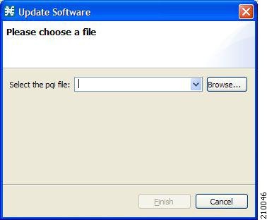
Step 3 ![]() Click Browse.
Click Browse.
A Select file dialog box appears.
Step 4 ![]() Browse to the PQI file that you are installing.
Browse to the PQI file that you are installing.
Step 5 ![]() Click Open.
Click Open.
The Select file dialog box closes.
Step 6 ![]() Click Finish.
Click Finish.
A Password Management dialog box appears.
Step 7 ![]() Enter the appropriate password. (For more information, see "Password Management" section.)
Enter the appropriate password. (For more information, see "Password Management" section.)
Step 8 ![]() Click Apply.
Click Apply.
The Password Management dialog box closes.
An Updating software to SCE progress bar appears.
The PQI file is installed on the selected Cisco SCE.
How to Install a Cisco SCE OS Software Package on Cisco SCE Devices
This operation installs the Cisco SCE OS software package (the operating system software and firmware of the Cisco SCE platform).
Note ![]() It is recommended to use the SCE Software Upgrade wizard when installing an SCE OS software package on multiple Cisco SCE platforms. See "How to Upgrade the SCE Using the SCE Software Upgrade Wizard" section.
It is recommended to use the SCE Software Upgrade wizard when installing an SCE OS software package on multiple Cisco SCE platforms. See "How to Upgrade the SCE Using the SCE Software Upgrade Wizard" section.
Step 1 ![]() In the Site Manager tree, select a Cisco SCE device.
In the Site Manager tree, select a Cisco SCE device.
Step 2 ![]() From the Console main menu, choose Network > Upgrade SCE Platform Firmware (PKG).
From the Console main menu, choose Network > Upgrade SCE Platform Firmware (PKG).
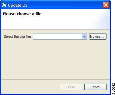
The Update OS dialog box appears (Figure 5-20).
Figure 5-20 Update OS
Step 3 ![]() Click Browse.
Click Browse.
A Select file dialog box appears.
Step 4 ![]() Browse to the PKG file containing the OS that you are installing.
Browse to the PKG file containing the OS that you are installing.
Step 5 ![]() Click Open.
Click Open.
The Select file dialog box closes.
Step 6 ![]() Click Finish.
Click Finish.
A Password Management dialog box appears.
Step 7 ![]() Enter the appropriate password. (For more information, see "Password Management" section.)
Enter the appropriate password. (For more information, see "Password Management" section.)
Step 8 ![]() Click Apply.
Click Apply.
The Password Management dialog box closes.
An Updating software to SCE progress bar appears.
The PQI file is installed on the selected Cisco SCE.
Managing Subscriber Manager Devices
•![]() How to Generate Tech Support Info Files for Subscriber Manager Devices
How to Generate Tech Support Info Files for Subscriber Manager Devices
•![]() How to Retrieve the Online Status of Subscriber Manager Devices
How to Retrieve the Online Status of Subscriber Manager Devices
•![]() How to Connect to Subscriber Manager Devices
How to Connect to Subscriber Manager Devices
How to Generate Tech Support Info Files for Subscriber Manager Devices
This operation generates the support file, for the Subscriber Manager, for the use of Cisco technical support staff.
Step 1 ![]() In the Site Manager tree, right-click an Subscriber Manager device.
In the Site Manager tree, right-click an Subscriber Manager device.
A popup menu appears (Figure 5-21).
Figure 5-21 Site Manager Tree Menu
Step 2 ![]() From the menu, select Generate Tech Support Info File.
From the menu, select Generate Tech Support Info File.
The Generate Tech Support Info File dialog box appears.
Step 3 ![]() Click Browse.
Click Browse.
A Select File dialog box appears.
Step 4 ![]() Browse to the folder where you want to save the tech support info file.
Browse to the folder where you want to save the tech support info file.
Step 5 ![]() In the File name field, enter a new file name, or select an existing ZIP file.
In the File name field, enter a new file name, or select an existing ZIP file.
Step 6 ![]() Click Open to select the file.
Click Open to select the file.
If the file exists, it is overwritten.
The Select File dialog box closes.
Step 7 ![]() (Optional) To add log files to the output tech support info file, check the Add GUI Console log files check box.
(Optional) To add log files to the output tech support info file, check the Add GUI Console log files check box.
Step 8 ![]() Check the Open file after it is fetched check box.
Check the Open file after it is fetched check box.
Step 9 ![]() Click Finish.
Click Finish.
The Generate Tech Support Info File dialog box closes.
A Password Management dialog box appears.
Step 10 ![]() Enter the appropriate password. (For more information, see "Password Management" section.)
Enter the appropriate password. (For more information, see "Password Management" section.)
Step 11 ![]() Click Generate.
Click Generate.
The Password Management dialog box closes.
A Generate tech support info file progress bar appears.
The file is generated.
How to Retrieve the Online Status of Subscriber Manager Devices
This operation provides information about the current software version and operational status of the Subscriber Manager Device.
Step 1 ![]() In the Site Manager tree, right-click an Subscriber Manager device.
In the Site Manager tree, right-click an Subscriber Manager device.
A popup menu appears.
Step 2 ![]() From the menu, select Online Status.
From the menu, select Online Status.
A Password Management dialog box appears.
Step 3 ![]() Enter the appropriate password. (For more information, see "Password Management" section.)
Enter the appropriate password. (For more information, see "Password Management" section.)
Step 4 ![]() Click Extract.
Click Extract.
The Password Management dialog box closes.
An Extracting info progress bar appears.
The SCMS Subscriber Manager online status is retrieved (Figure 5-22).
Figure 5-22 SCMS Subscriber Manager Online Status

How to Connect to Subscriber Manager Devices
To manage subscribers using the Subscriber Manager GUI tool, you must connect to an Subscriber Manager device.
Note ![]() The Subscriber Manager GUI tool performs authentication on the SCMS Subscriber Manager by opening a PRPC connection to port 14374 and attempting to log in using the username and password that you entered in the Password Management dialog box. If a PRPC server with this user is not running on the SCMS Subscriber Manager, authentication fails.
The Subscriber Manager GUI tool performs authentication on the SCMS Subscriber Manager by opening a PRPC connection to port 14374 and attempting to log in using the username and password that you entered in the Password Management dialog box. If a PRPC server with this user is not running on the SCMS Subscriber Manager, authentication fails.
If you have changed the PRPC port on the SCMS Subscriber Manager, see "User Authentication" section.
Step 1 ![]() In the Site Manager tree, right-click an Subscriber Manager device.
In the Site Manager tree, right-click an Subscriber Manager device.
A popup menu appears.
Step 2 ![]() From the menu, select Manage Subscribers.
From the menu, select Manage Subscribers.
A Password Management dialog box appears.
Step 3 ![]() Enter the appropriate password. (For more information, see "Password Management" section.)
Enter the appropriate password. (For more information, see "Password Management" section.)
Step 4 ![]() Click Connecting.
Click Connecting.
The Password Management dialog box closes.
A Connecting to progress bar appears.
You connect to the Subscriber Manager, and the Console switches to the Subscriber Manager GUI tool.
For an explanation of how to proceed, see "Using the Subscriber Manager GUI Tool" section.
Managing Collection Manager Devices
You can configure Collection Manager devices using a wizard. (See "How to Configure Cisco SCE and Collection Manager Devices Using a Wizard" section.)
How to Retrieve the Online Status of CM Devices
This operation provides information about the current software version and operational status of the Collection Manager.
Step 1 ![]() In the Site Manager tree, right-click a CM device.
In the Site Manager tree, right-click a CM device.
A popup menu appears (Figure 5-23).
Figure 5-23 Site Manager Tree Menu
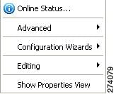
Step 2 ![]() From the menu, select Online Status.
From the menu, select Online Status.
A Password Management dialog box appears.
Step 3 ![]() Enter the appropriate password. (For more information, see "Password Management" section.)
Enter the appropriate password. (For more information, see "Password Management" section.)
Step 4 ![]() Click Extract.
Click Extract.
The Password Management dialog box closes.
An Extracting info progress bar appears.
The SCMS Collection Manager online status is retrieved.
For an example of a retrieved online status window (for a Cisco SCE platform), see "How to Retrieve the Online Status of Cisco SCE Devices" section.
Managing Database Devices
This section provides information on managing database devices.
How to Make Databases Accessible to the SCA Reporter
•![]() The Reporter DB Configuration wizard allows you to connect the Reporter to a single database. (See "How to Use the Reporter DB Configuration Wizard" section.)
The Reporter DB Configuration wizard allows you to connect the Reporter to a single database. (See "How to Use the Reporter DB Configuration Wizard" section.)
•![]() An alternative procedure is described in the "Configuring Properties" section in the "Using the Cisco Service Control Application Reporter" chapter of the Cisco Service Control Application Reporter User Guide.
An alternative procedure is described in the "Configuring Properties" section in the "Using the Cisco Service Control Application Reporter" chapter of the Cisco Service Control Application Reporter User Guide.
Step 1 ![]() In the Site Manager tree, right-click a database device.
In the Site Manager tree, right-click a database device.
A popup menu appears (Figure 5-24).
Figure 5-24 Site Manager Tree Menu
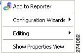
Step 2 ![]() From the menu, select Add to Reporter.
From the menu, select Add to Reporter.
The Preferences dialog box appears (Figure 5-25).
Figure 5-25 Preferences
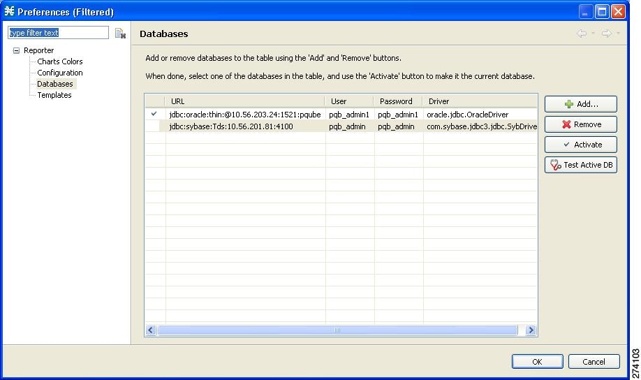
Step 3 ![]() Click Add.
Click Add.
The Add Database wizard appears (Figure 5-26).
Figure 5-26 Add Database
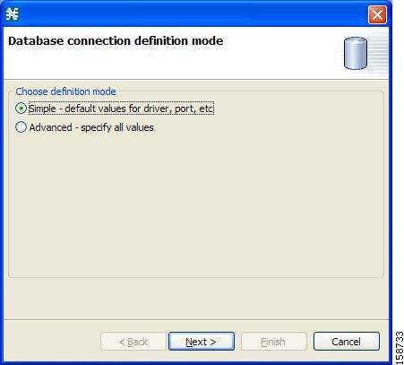
Step 4 ![]() Select one of the Choose definition mode radio buttons:
Select one of the Choose definition mode radio buttons:
•![]() Simple - default values of driver, port, etc.
Simple - default values of driver, port, etc.
•![]() Advanced - specify all values
Advanced - specify all values
Step 5 ![]() Click Next.
Click Next.
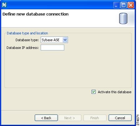
The Define new database connection page of the Add Database wizard opens:
•![]() If you selected Simple in Step 4, the Define new database connection page looks like Figure 5-27.
If you selected Simple in Step 4, the Define new database connection page looks like Figure 5-27.
Figure 5-27 Define New Database Connection - Simple
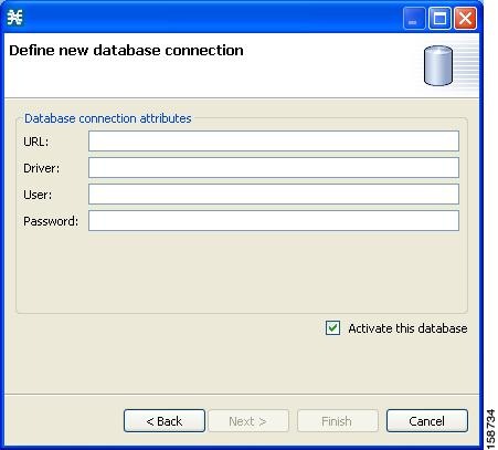
•![]() If you selected Advanced in Step 4, the Define new database connection page looks like Figure 5-28.
If you selected Advanced in Step 4, the Define new database connection page looks like Figure 5-28.
Figure 5-28 Define New Database Connection - Advanced
Step 6 ![]() Fill in all the fields.
Fill in all the fields.
Step 7 ![]() Click Finish.
Click Finish.
The Add Database wizard closes.
The definition of the database is added to the list in the Preferences dialog box.
Step 8 ![]() Repeat Steps 3 to 7 for other databases.
Repeat Steps 3 to 7 for other databases.
Step 9 ![]() If necessary, delete databases from the list in the Preferences dialog box.
If necessary, delete databases from the list in the Preferences dialog box.
Step 10 ![]() Make sure that the correct database is activated.
Make sure that the correct database is activated.
Step 11 ![]() Click OK.
Click OK.
The Preferences dialog box closes.
Working with Network Navigator Configuration Files
After you add sites and devices to the Network Navigator, you can export this data to a file to back up your settings and to share them with other users, who can import your Network Navigator settings into their Console.
If you use the Site Master Password to store the passwords of the network devices, the passwords are also exported, in encrypted form. This means that other users who import this data need to only provide the Site Master Password to access the devices.
•![]() How to Export a Network Navigator Configuration
How to Export a Network Navigator Configuration
•![]() How to Import a Network Navigator Configuration
How to Import a Network Navigator Configuration
How to Export a Network Navigator Configuration
Step 1 ![]() From the Console main menu, choose File > Export.
From the Console main menu, choose File > Export.
The Export dialog box appears (Figure 5-29).
Figure 5-29 Export
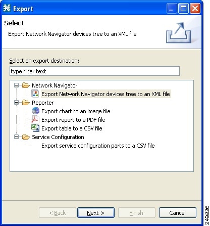
Step 2 ![]() From the export destination list, select Network Navigator Configuration to a file.
From the export destination list, select Network Navigator Configuration to a file.
Step 3 ![]() Click Next.
Click Next.
The Export Network Navigator Configuration to a file dialog box appears (Figure 5-30).
Figure 5-30 Import Network Navigator Configuration from File
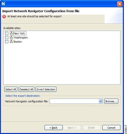
The Available sites pane lists all of the sites in the configuration.
Step 4 ![]() Select the sites to export, using the check boxes and the select buttons.
Select the sites to export, using the check boxes and the select buttons.
Step 5 ![]() In the Select the export destination area, click Browse.
In the Select the export destination area, click Browse.
An Open dialog box appears.
Step 6 ![]() Browse to the folder where you want to save the configuration file.
Browse to the folder where you want to save the configuration file.
Step 7 ![]() In the File name field, enter a new file name, or select an existing site_xml file.
In the File name field, enter a new file name, or select an existing site_xml file.
Step 8 ![]() Click Open to select the file.
Click Open to select the file.
Note ![]() If the file exists, it is overwritten.
If the file exists, it is overwritten.
The Open dialog box closes.
Step 9 ![]() Click Finish.
Click Finish.
The Export Network Navigator Configuration dialog box closes.
The configuration is saved to the file.
How to Import a Network Navigator Configuration
Step 1 ![]() From the Console main menu, choose File > Import.
From the Console main menu, choose File > Import.
The Import dialog box appears (Figure 5-31).
Figure 5-31 Import
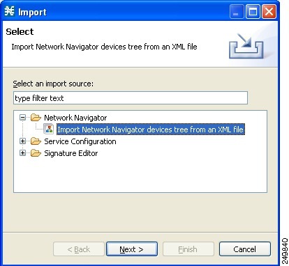
Step 2 ![]() From the import source list, select Network Navigator Configuration from file.
From the import source list, select Network Navigator Configuration from file.
Step 3 ![]() Click Next.
Click Next.
The Import Network Navigator Configuration from file dialog box appears (Figure 5-32).
Figure 5-32 Import Network Navigator Configuration from File
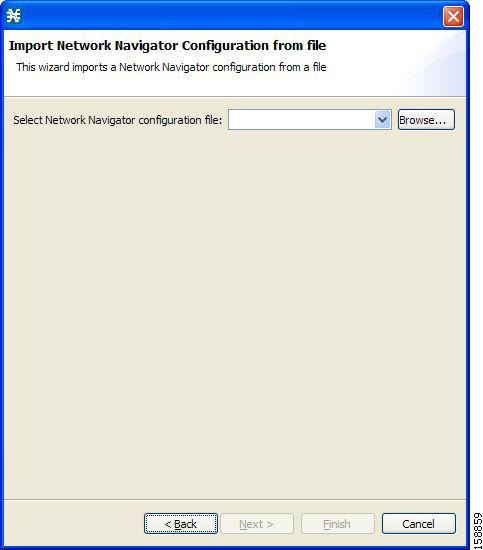
Step 4 ![]() Click Browse.
Click Browse.
An Open dialog box appears.
Step 5 ![]() Browse to the folder containing the file to import, and select a site_xml file.
Browse to the folder containing the file to import, and select a site_xml file.
Step 6 ![]() Click Open to select the file.
Click Open to select the file.
The Open dialog box closes.
Step 7 ![]() Click Finish.
Click Finish.
The Import Network Navigator Configuration dialog box closes.
The configuration is imported from the file.
Network Settings Requirements
•![]() How to Disable PRPC Authentication
How to Disable PRPC Authentication
Firewall/NAT Requirements
Table 5-1 lists the firewall/NAT open port settings required for the Network Navigator to operate properly.
The ports listed in the table are the default values. If you change a port in a device, you must modify the firewall/NAT settings accordingly. (Modifying the Console settings to connect to a different PRPC port is described in the following section.)
The SCA Reporter may have additional requirements for connecting to the database. For more information, see the Cisco Service Control Application Reporter User Guide.
User Authentication
User authentication is performed when a Proprietary Remote Procedure Call (PRPC) connection is made to a Cisco SCE platform, a CM, or an Subscriber Manager. For authentication to succeed, a PRPC server must be running at the destination, and you must know the username and password of a user of the server.
Note ![]() If you change a PRPC server port in a device (SM/CM/Cisco SCE), you must add a line to the configuration file engage.ini:
If you change a PRPC server port in a device (SM/CM/Cisco SCE), you must add a line to the configuration file engage.ini:<IP address of device>.rpc.port=<port number>For example:10.56.216.37.rpc.port=222Add one line for each (non-default) port that you use.
The file engage.ini is located in the folder Program files\Cisco SCA\SCA BB Console 3.8.x\plugins\policy.contribution_3.8.x\config\.
You define the username and password using the user/password mechanism in the Cisco SCE platform or a command-line utility in the Subscriber Manager and CM.
For more information about defining users, see the following:
•![]() Cisco SCE—See either the "TACACS+ Authentication, Authorization, and Accounting" section in the "Configuring the Management Interface and Security" chapter of Cisco SCE8000 10GBE Software Configuration Guide or the "TACACS+ Authentication, Authorization, and Accounting" section in the "Configuring the Management Interface and Security" chapter of Cisco SCE8000 GBE Software Configuration Guide.
Cisco SCE—See either the "TACACS+ Authentication, Authorization, and Accounting" section in the "Configuring the Management Interface and Security" chapter of Cisco SCE8000 10GBE Software Configuration Guide or the "TACACS+ Authentication, Authorization, and Accounting" section in the "Configuring the Management Interface and Security" chapter of Cisco SCE8000 GBE Software Configuration Guide.
•![]() Collection Manager—"Managing Users" section in the "Managing the Collection Manager" chapter of Cisco Service Control Management Suite Collection Manager User Guide.
Collection Manager—"Managing Users" section in the "Managing the Collection Manager" chapter of Cisco Service Control Management Suite Collection Manager User Guide.
•![]() Subscriber Manager—"Information About the p3rpc Utility" section in the "Command-Line Utilities" appendix of Cisco Service Control Management Suite Subscriber Manager User Guide.
Subscriber Manager—"Information About the p3rpc Utility" section in the "Command-Line Utilities" appendix of Cisco Service Control Management Suite Subscriber Manager User Guide.
Note ![]() PRPC authentication from the Cisco SCA BB Console to any CM/SM/Cisco SCE IP addresses other than the real IP address of the device is not supported. This is especially important when the CM/Subscriber Manager/Cisco SCE resides on the inside interface of a NATing router or firewall
PRPC authentication from the Cisco SCA BB Console to any CM/SM/Cisco SCE IP addresses other than the real IP address of the device is not supported. This is especially important when the CM/Subscriber Manager/Cisco SCE resides on the inside interface of a NATing router or firewall
Workaround:
Redesign your network so that the SCA BB Console is given the real IP address of the CM/SM/Cisco SCE.
Disable PRPC authentication on the Cisco SCE/CM/Subscriber Manager as described in the following sections.
How to Disable PRPC Authentication
•![]() How to Disable PRPC Authentication on a Cisco SCE Platform
How to Disable PRPC Authentication on a Cisco SCE Platform
•![]() How to Disable PRPC Authentication on a CM
How to Disable PRPC Authentication on a CM
•![]() How to Disable PRPC Authentication on an Subscriber Manager
How to Disable PRPC Authentication on an Subscriber Manager
How to Disable PRPC Authentication on a Cisco SCE Platform
Step 1 ![]() Use the CLI to disable PRPC authentication.
Use the CLI to disable PRPC authentication.
Run the following CLI in config mode:
ip rpc-adapter security-level none
How to Disable PRPC Authentication on a CM
Step 1 ![]() Edit the CM configuration file.
Edit the CM configuration file.
Edit the cm/um/config/p3cm.cfg configuration file:
[RPC.Server]
security_level=none
Step 2 ![]() Reload the CM process.
Reload the CM process.
How to Disable PRPC Authentication on an Subscriber Manager
Step 1 ![]() Edit the Subscriber Manager configuration file.
Edit the Subscriber Manager configuration file.
Edit the ~pcube/sm/server/root/config/p3sm.cfg configuration file:
[RPC.Server]
security_level=none
Step 2 ![]() Load the configuration.
Load the configuration.
Run the following CLU:
p3sm --load-config
 Feedback