Maintaining the Cisco CMC
Available Languages
Contents
Maintaining the Cisco CMC
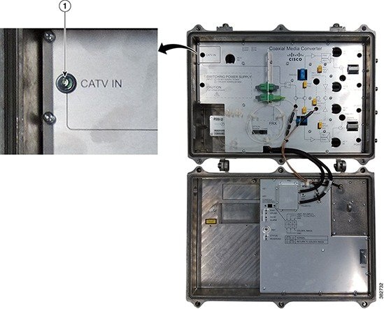
Opening the Cisco CMC
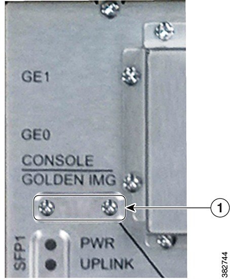
Using the Console Port on the Cisco CMC
The console port on the Cisco CMC is used for connecting the Cisco CMC to a PC using a console cable.
Warning
The console cable connection is only for initial installation and maintenance of the Cisco CMC. The console cable must not be connected during electromagnetic compliance testing. The console cable must be disconnected from the Cisco CMC after the final installation.
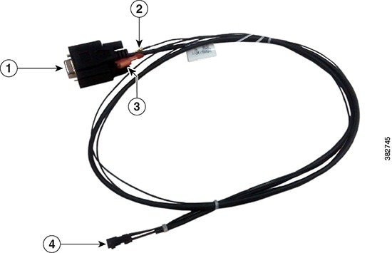
The figure below shows the console cable used with the Cisco CMC.
The table below provides the console cable connector pin definitions.
Before You BeginProcedure
- Open the Cisco CMC lid. See Opening the Cisco CMC.
- Have the following tools ready before performing this task:
What to Do Next
- Disconnect the console cable from the console port.
- Reinstall the console port cover and tighten the screws using a screwdriver.
- Close the Cisco CMC lid. See Closing the Cisco CMC.
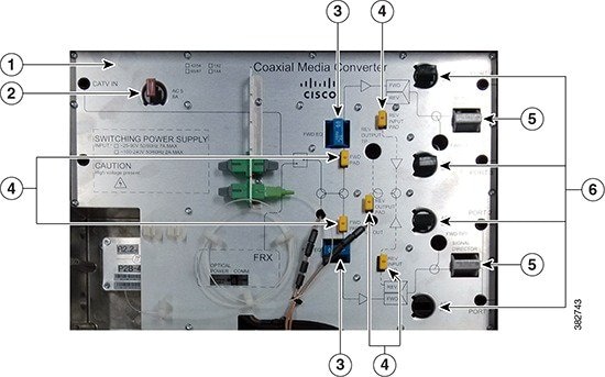
Removing and Installing the Accessories on the Cisco CMC
This section provides information on how to remove and install the following accessories located inside the Cisco CMC.
Accessory
Description
Illustration
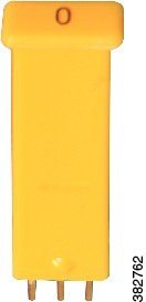
Attenuator pads
An attenuator pad produces flat (even) loss across the forward and reverse frequency spectrums. It is used during the station balancing to adjust signal levels. The loss (in dB) produced by an attenuator pad is equal to the value printed on the top of the attenuator pad. An attenuator pad with 75 Ω printed on the top works as a 75 ohm terminator.
Important:Do not change the attenuator pads, unless specified by the system design.
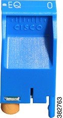
Equalizers
An equalizer produces linear tilt. It must be used on the Cisco CMC if the output tilt does not have the desired output tilt. The EQ value specified on the equalizer is the amount of tilt from lowest to highest frequency (52 to 1002 MHz).
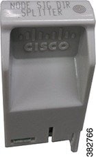
Signal director—Splitter
A splitter splits the RF input signal to feed two RF output ports. It is used for configuring the 4-way RF configuration on the Cisco CMC.
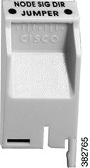
Signal director—Jumper
A jumper routes the RF input signal to the RF output port. It is used for configuring the 2-way RF configuration on the Cisco CMC.
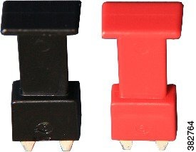
AC shunts
An AC shunt is used for configuring the power direction in the Cisco CMC with the 60VAC power supply unit. Use the red AC shunt for the RF input port and black AC shunts for the RF output ports.
Warning Remove all the AC shunts if they are installed in the Cisco CMC before connecting the coaxial cables to the F-connectors.
Note Do not use AC shunts in the Cisco CMC with the 220VAC power supply unit.
These accessories can be removed and installed in the Cisco CMC through the cutouts in the base cover.
Before You BeginProcedureOpen the Cisco CMC lid. See Opening the Cisco CMC.
What to Do Next
Close the Cisco CMC lid. See Closing the Cisco CMC.
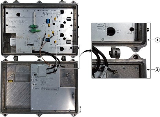
Removing the Coaxial Cable from the Cisco CMC
Before You BeginProcedure
- Open the Cisco CMC lid. See Opening the Cisco CMC.
- Have the following tools ready before performing this task:
Step 1 Remove the coaxial cable from the F-connector installed in the RF port. Step 2 Loosen the seizure screw, do not remove it. The figure below shows the location of the seizure screw inside the Cisco CMC. Step 3 Loosen the connector nut using a torque wrench and remove the F-connector from the RF port. Step 4 Reinstall the PG11-to-5/8" adapter plug in the RF port and tighten using a torque wrench (4.63 ft-lb or 6.25 Nm), if you removed a PG11 F-connector from the RF port. Step 5 Check if RF signal is present at the unused RF ports and perform one of the following:
What to Do Next
- To install the F-connector and connect the coaxial cable to the Cisco CMC, see Installing the Coaxial Cables on the Cisco CMC.
- Close the Cisco CMC lid. See Closing the Cisco CMC.
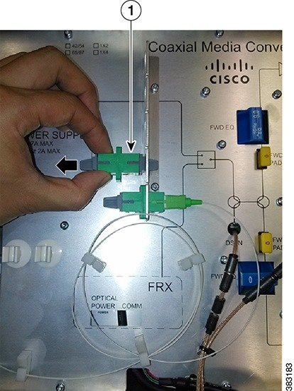
Removing the Fiber Adapter from the Cisco CMC
Before You BeginProcedureOpen the Cisco CMC lid. See Opening the Cisco CMC.
What to Do Next
- To install a fiber adapter, see Installing a Fiber Adapter on the Cisco CMC.
- Close the Cisco CMC lid. See Closing the Cisco CMC.
Removing the SFP Module from the Cisco CMC
Before You BeginProcedure
- Open the Cisco CMC lid. See Opening the Cisco CMC.
- Have the following tools ready before performing this task:
Step 1 Perform one of the following and immediately reinstall the dust plug in the SFP module:
- Disconnect the optical fiber connected to the SFP module. If the fiber port does not have any other optical fibers, remove the gland. Reinstall the 5/8" port plug in the fiber port and tighten to 6.7 ft-lb (9 Nm) using a torque wrench.
- Disconnect the RJ-45 cable connected to the SFP module. If the RJ-45 port does not have any other RJ-45 cables, remove the PG16 gland using a torque wrench. Reinstall the PG16 port plug in the RJ-45 port and tighten using a torque wrench.
Step 2 Unlock and remove the SFP module from the socket connector using one of the following:
If the SFP module has a Mylar tab latch, pull the tab gently in a slightly downward direction until the SFP module disengages from the socket connector, and then pull the SFP module straight out of the socket. Do not twist or pull the Mylar tab as it can detach from the SFP module.
If the SFP module has an Actuator button latch, gently press the Actuator button on the front of the SFP module until it clicks and the latch mechanism releases the SFP module from the socket connector. Grasp the Actuator button between your thumb and index finger, and carefully pull the SFP module straight from the socket.
If the SFP module has a Bale-clasp latch, pull the bale to eject the SFP module from the socket. If the Bale-clasp latch is obstructed and you cannot use your index finger to open it, use a small, flat-blade screwdriver or a long narrow instrument to open the bale-clasp latch. Grasp the SFP module between your thumb and index finger, and carefully remove it from the socket.
Step 3 Place the removed SFP module in an antistatic bag.
What to Do Next
- To install the SFP module, see Installing an SFP Module on the Cisco CMC.
- Close the Cisco CMC lid. See Closing the Cisco CMC.
Closing the Cisco CMC
Proper housing closure is important to maintain the Cisco CMC in good working condition. Proper closure ensures a good seal against the environment and protects the internal modules.
Caution
Avoid moisture damage and RF leakage. Follow the procedure exactly as shown below to ensure a proper seal.
The Cisco CMC has waterproof rubber and EMI gasket to seal the equipment.
Before You BeginProcedure
- Ensure that the waterproof rubber and EMI gasket on the Cisco CMC are not worn out. Wipe off any excess dirt and debris. If the waterproof rubber or EMI gasket is worn out, contact the Cisco Technical Assistance Center (TAC) for further assistance.
- Have the following tools ready before performing this task:
Step 1 Close the lid.
Caution Ensure that all the cables are out of the way when closing the lid.
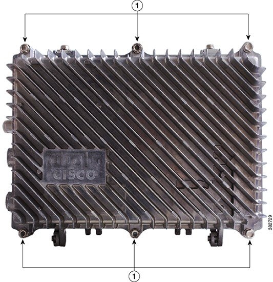
Step 2 Lightly secure the six 1/2-inch closure bolts using a hex driver or ratchet. Step 3 Tighten the six housing closure bolts from 5 ft-lb to 12 ft-lb (6.8 Nm to 16.3 Nm) using a torque wrench in the correct sequence as shown in the figure below. Step 4 Using the same sequence, tighten the closure bolts again with the same torque specification to ensure proper closure.
Notices
Copyright © 2014, Cisco Systems, Inc. All rights reserved.


 Feedback