Configure 802.1Q Trunking Between Catalyst Switches
Available Languages
Download Options
Bias-Free Language
The documentation set for this product strives to use bias-free language. For the purposes of this documentation set, bias-free is defined as language that does not imply discrimination based on age, disability, gender, racial identity, ethnic identity, sexual orientation, socioeconomic status, and intersectionality. Exceptions may be present in the documentation due to language that is hardcoded in the user interfaces of the product software, language used based on RFP documentation, or language that is used by a referenced third-party product. Learn more about how Cisco is using Inclusive Language.
Contents
Introduction
This document describes the difference of IEEE 802.1Q (dot1q) trunking between Cisco Catalyst switches that run Cisco IOS® Software.
Prerequisites
Requirements
Ensure that you meet these requirements before you attempt this configuration:
-
Knowledge of IEEE 802.1Q trunking
-
Knowledge of the configuration of Catalyst 3560 and Catalyst 6500/6000 series switches with use of command-line interface (CLI)
Components Used
The information in this document is based on these software and hardware versions:
-
Catalyst 3560 switch that runs Cisco IOS Software Release 12.2(25)SEA
-
Catalyst 6509 switch that runs Cisco IOS Software Release 12.1(26)E1
The information in this document was created from the devices in a specific lab environment. All of the devices used in this document started with a cleared (default) configuration. If your network is live, ensure that you understand the potential impact of any command.
Background Information
This document provides a sample configuration of IEEE 802.1Q (dot1q) trunking between a Cisco Catalyst 3550/3560/3750 switch that runs Cisco IOS® Software and a Catalyst 6500/6000 series switch or Catalyst 4500/4000 series switch that runs Cisco IOS Software. Trunking is a way to carry traffic from several VLANs over a point-to-point link between the two devices.
Two ways in which you can implement Ethernet trunking are:
-
Inter-Switch Link Protocol (ISL)—A Cisco proprietary protocol
-
802.1Q—An IEEE standard
Catalyst Components
The Catalyst 3560 configuration in this document is also applicable to Catalyst 3550/3750 switches that run Cisco IOS Software. The Catalyst 6500/6000 configuration in this document is also applicable to Catalyst 4500/4000 series switches that run Cisco IOS Software.
Note: Refer to this next document to learn about the trunking methods that are supported by various Catalyst switches:
-
System Requirements to Implement Trunkingon Catalyst switches
Note: This document includes only the configuration files from the switches and the output from the related sample show commands. For details on how to configure an 802.1Q trunk between Catalyst switches, refer to these next documents:
-
Configuring VLAN Trunks section of Configuring VLANs—Catalyst 3560 series switches
- Understanding VLAN Trunks section of Configuring Layer 2 Ethernet Interfaces —Catalyst 4500 series switches that run Cisco IOS Software
Background Theory
IEEE 802.1Q uses an internal tagging mechanism. The trunking device inserts a 4-byte tag in order to identify the VLAN to which a frame belongs and then recomputes the frame check sequence (FCS). For more information, refer to these documents:
-
Basic Characteristics of 802.1Q Trunking section of Trunking Between Catalyst 4500/4000, 5500/5000, and 6500/6000 Series Switches Using 802.1Q Encapsulation with Cisco CatOS System Software
Note: Next are important notes to remember for this configuration:
-
Any Ethernet interface on a Catalyst 3550/3560/3750 series switch can support 802.1Q and ISL encapsulation. The Ethernet interface on a Catalyst 3550 switch is a Layer 2 (L2) port, by default.
-
Any Ethernet port on a Catalyst 6500/6000 series switch can support 802.1Q and ISL encapsulation.
-
By default, the Catalyst 4500 series switch that runs Cisco IOS Software supports both ISL and 802.1Q trunking modes. The support is on all interfaces except blocking Gigabit ports on the WS-X4418-GB and WS-X4412-2GB-T modules. These ports do not support ISL and only support 802.1Q trunking. Ports 3 through 18 are blocking Gigabit ports on the WS-X4418-GB module. Ports 1 through 12 are blocking Gigabit ports on the WS-X4412-2GB-T module.
Note: A port is a blocking port if its connection to the backplane is oversubscribed.
-
The main difference between the Catalyst 6500/6000 and the Catalyst 4500 platforms is the default interface configuration. The Catalyst 6500/6000 switch that runs Cisco IOS Software has interfaces in shutdown mode that are Layer 3 (L3) routed ports by default. The Catalyst 4500/4000 switch that runs Cisco IOS Software has all the interfaces enabled. The interfaces are L2 switch ports by default.
-
When 802.1Q encapsulation is used on a trunk interface on the Catalyst 3750 Switches, runts can be seen on
show interfaceoutput because valid 802.1Q encapsulated packets which are 61-64 bytes that include the q-tag are counted by the Catalyst 3750 Switch as undersized frames, even though these packets are forwarded correctly. For more details, refer to Cisco bug ID CSCec14238 .
.
Note: Only registered Cisco users have access to internal Cisco tools and information.
Configure
In this section, you are presented with the information to configure the features described in this document.
Note: Use the Command Lookup Tool to obtain more information on the commands used in this section.
Note: Only registered Cisco users have access to internal Cisco tools and information.
Network Diagram
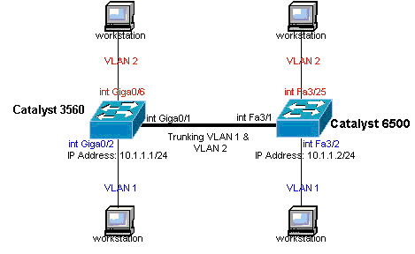
This document uses this network setup:
Note: The Gigabit Ethernet interface on the Catalyst 3560 is a 10/100/1000 Mbps negotiated Ethernet interface. Therefore, the Gigabit port on the Catalyst 3560 is connected to a Fast Ethernet (100 Mbps) port on the Catalyst 6500 in this network diagram.
 Network Diagram
Configurations
This document uses these configurations:
| Catalyst 3560 Switch |
|---|
!--- Notice: This example creates VLAN 1 and VLAN 2 |
| Catalyst 6500 Switch |
|---|
!--- Notice: This example creates VLAN 1 and VLAN 2 and sets |
Note: If you assign an interface to a VLAN that does not exist, the interface shuts down until you create the VLAN in the VLAN database. For details, refer to the Creating or Modifying an Ethernet VLAN section of Configuring VLANs.
Verify
Use this section to confirm that your configuration works properly.
The Output Interpreter Tool (OIT) supports certain show commands. Use the OIT to view an analysis of show command output.
Note: Only registered Cisco users have access to internal Cisco tools and information.
On Catalyst 3550/3560/3750/6500/4500 switches, use these commands:
-
show interfacesinterface_typemodule/porttrunk
-
show interfacesinterface_typemodule/portswitchport
-
show vlan
-
show vtp status
Sample show Command Output
Catalyst 3560 Switch
-
show interfaces interface_type module/por trunk —This command displays the trunk configuration of the interface along with the VLAN numbers for which traffic is able to be carried over the trunk.
3560# show interface gigabitethernet 0/1 trunk

Port      Mode         Encapsulation  Status        Native vlan
Gi0/1     on           802.1q         trunking      1

Port      Vlans allowed on trunk
Gi0/1     1 4094

Port      Vlans allowed and active in management domain
Gi0/1     1-2

Port      Vlans in spanning tree forwarding state and not pruned
Gi0/1     1-2
-
show interfaces interface_type module/port switchport —This command displays the switch port configuration of the interface.
In the display, check the Operational Mode and the Operational Trunking Encapsulation fields.
3560# show interface gigabitethernet 0/1 switchport
Name: Gi0/1
Switchport: Enabled
Administrative Mode: trunk
Operational Mode: trunk
Administrative Trunking Encapsulation: dot1q
Operational Trunking Encapsulation: dot1q
Negotiation of Trunking: On
Access Mode VLAN: 1 (default)
Trunking Native Mode VLAN: 1 (default)
Voice VLAN: none
Administrative private-vlan host-association: none
Administrative private-vlan mapping: none
Administrative private-vlan trunk native VLAN: none
Administrative private-vlan trunk encapsulation: dot1q
Administrative private-vlan trunk normal VLANs: none
Administrative private-vlan trunk private VLANs: none
Operational private-vlan: none
Trunking VLANs Enabled: ALL
Pruning VLANs Enabled: 2-1001
Capture Mode Disabled
Capture VLANs Allowed: ALL
Protected: false
Unknown unicast blocked: disabled
Unknown multicast blocked: disabled
Appliance trust : none
-
show vlan—This command gives information about the VLANs and the ports that belong to a particular VLAN.
3560# show vlan VLAN Name Status Ports ---- -------------------------------- --------- ------------------------------- 1 default active Gi0/2, Gi0/3, Gi0/4, Gi0/5 2 VLAN0002 active Gi0/6, Gi0/7, Gi0/8, Gi0/9 Gi0/10, Gi0/11, Gi0/12 1002 fddi-default act/unsup 1003 token-ring-default act/unsup 1004 fddinet-default act/unsup 1005 trnet-default act/unsup !--- Output suppressed.Note: The ports that are displayed in the output are only access ports. But the ports that are configured to be trunk and that are in the 'notconnected' status also show up in the show vlan output.
-
show vtp status—This command displays general information about the VTP management domain, status, and counters.
3560# show vtp status
VTP Version : 2
Configuration Revision : 0
Maximum VLANs supported locally : 1005
Number of existing VLANs : 6
VTP Operating Mode : Transparent
VTP Domain Name :
VTP Pruning Mode : Disabled
VTP V2 Mode : Disabled
VTP Traps Generation : Disabled
MD5 digest : 0x4A 0x55 0x17 0x84 0xDB 0x99 0x3F 0xD1
Configuration last modified by 10.1.1.1 at 0-0-00 00:00:00

3560# ping 10.1.1.2
Type escape sequence to abort.
Sending 5, 100-byte ICMP Echos to 10.1.1.2, timeout is 2 seconds:
!!!!!
Success rate is 100 percent (5/5), round-trip min/avg/max = 1/1/4 ms
3560#
Catalyst 6500 Switch
-
show interfacesinterface_type module/porttrunk—This command displays the trunk configuration of the interface along with the VLAN numbers for which traffic is able to be carried over the trunk.
Cat6500# show interfaces fastethernet 3/1 trunk

Port      Mode         Encapsulation  Status        Native vlan
Fa3/1     on           802.1q         trunking      1

Port      Vlans allowed on trunk
Fa3/1     1 4094

Port      Vlans allowed and active in management domain
Fa3/1     1-2

Port      Vlans in spanning tree forwarding state and not pruned
Fa3/1     1-2
-
show interfacesinterface_typemodule/portswitchport —This command displays the switch port configuration of the interface. In the display, check the Operational Mode and the Operational Trunking Encapsulation fields.
cat6500# show interface fastethernet 3/1 switchport
Name: Fa3/1
Switchport: Enabled
Administrative Mode: trunk
Operational Mode: trunk
Administrative Trunking Encapsulation: dot1q
Operational Trunking Encapsulation: dot1q
Negotiation of Trunking: On
Access Mode VLAN: 1 (default)
Trunking Native Mode VLAN: 1 (default)
Voice VLAN: none
Administrative private-vlan host-association: none
Administrative private-vlan mapping: none
Administrative private-vlan trunk native VLAN: none
Administrative private-vlan trunk encapsulation: dot1q
Administrative private-vlan trunk normal VLANs: none
Administrative private-vlan trunk private VLANs: none
Operational private-vlan: none
Trunking VLANs Enabled: ALL
Pruning VLANs Enabled: 2-1001
Capture Mode Disabled
Capture VLANs Allowed: ALL
-
show vlan—This command gives information about the VLANs and the ports that belong to a particular VLAN.
Cat6500# show vlan

VLAN Name                             Status    Ports
---- -------------------------------- --------- -------------------------------
1    default                          active    Fa3/2, Fa3/3, Fa3/4, Fa3/5
                                                Fa3/6, Fa3/7, Fa3/8, Fa3/9
                                                Fa3/10, Fa3/11, Fa3/12, Fa3/13
                                                Fa3/14, Fa3/15, Fa3/16, Fa3/17
                                                Fa3/18, Fa3/19, Fa3/20, Fa3/21
                                                Fa3/22, Fa3/23, Fa3/24
2    VLAN0002                         active    Fa3/25, Fa3/26, Fa3/27, Fa3/28
                                                Fa3/29, Fa3/30, Fa3/31, Fa3/32
                                                Fa3/33, Fa3/34, Fa3/35, Fa3/36
                                                Fa3/37, Fa3/38, Fa3/39, Fa3/40
                                                Fa3/41, Fa3/42, Fa3/43, Fa3/44
                                                Fa3/45, Fa3/46, Fa3/47, Fa3/48
1002 fddi-default                      act/unsup
1003 token-ring-default                act/unsup
1004 fddinet-default                   act/unsup
1005 trnet-default                     act/unsup


!--- Output suppressed.
Note: The ports that display are only those ports that you have configured as Layer 2 nontrunk (access) ports. The ports that are configured to be trunk and that are in the 'notconnected' status also show up in the show vlan output. For details, refer to the Configuring LAN Interfaces for Layer 2 Switching section of Configuring LAN Ports for Layer 2 Switching.
-
show vtp status—This command displays general information about the VTP management domain, status, and counters.
Cat6500# show vtp status
VTP Version                     : 2
Configuration Revision          : 0
Maximum VLANs supported locally : 1005
Number of existing VLANs        : 6
VTP Operating Mode              : Transparent
VTP Domain Name                 :
VTP Pruning Mode                : Disabled
VTP V2 Mode                     : Disabled
VTP Traps Generation            : Disabled
MD5 digest                      : 0xBF 0x86 0x94 0x45 0xFC 0xDF 0xB5 0x70
Configuration last modified by 10.1.1.2 at 0-0-00 00:00:00
-
ping
Cat6500# ping 10.1.1.1

Type escape sequence to abort.
Sending 5, 100-byte ICMP Echos to 10.1.1.1, timeout is 2 seconds:
!!!!!
Success rate is 100 percent (5/5), round-trip min/avg/max = 1/1/4 ms
Troubleshoot
There is currently no specific troubleshoot information available for this configuration. For common problems that relate to trunking and 802.1Q configuration, refer to the Common Errors section of the document Trunking Between Catalyst 4500/4000, 5500/5000, and 6500/6000 Series Switches Using 802.1Q Encapsulation with Cisco CatOS System Software.
Related Information
Revision History
| Revision | Publish Date | Comments |
|---|---|---|
2.0 |
19-Jan-2023 |
Update formatting. Fix CCW Alerts. Recertification. |
1.0 |
29-Nov-2001 |
Initial Release |
Contributed by Cisco Engineers
 Feedback
Contact Cisco
- Open a Support Case

- (Requires a Cisco Service Contract)