Configuring Site-to-Site VPN on the RV160 and RV260
Available Languages
Objective
The objective of this document is to create a site-to-site VPN on the RV160 and RV260 series routers.
Introduction
A virtual private network (VPN) is a great way to connect remote workers to a secured network. A VPN allows a remote host to act as if they were connected to the onsite secured network. In a site-to-site VPN, the local router at one location connects to a remote router through a VPN tunnel. This tunnel encapsulates data securely by using industry-standard encryption and authentication techniques to secure data sent.
Note that when you are configuring site-to-site VPN, the Local Area Network (LAN) subnets on either side of the tunnel cannot be on the same network. For example, if the Site A LAN uses the 192.168.1.x/24 subnet, Site B cannot use the same subnet. Site B have to use a different subnet like 192.168.2.x/24.
To configure a tunnel properly, enter corresponding settings (reversing local and remote) when configuring the two routers. Assume that this router is identified as Router A. Enter its settings in the Local Group Setup section while entering the settings for the other router (Router B) in the Remote Group Setup section. When you configure the other router (Router B), enter its settings in the Local Group Setup section, and enter the Router A settings in the Remote Group Setup.
Below is a table of the configuration for both Router A and Router B, highlighted in bold are parameters that are the inverse of the opposite router. All other parameters remain are configured the same. In this document, we will be configuring the local router using Router A.
|
Fields |
Router A (Local) WAN IP address: 140.x.x.x Local IP address: 192.168.2.0/24 |
Router B (Remote) WAN IP address: 145.x.x.x Local IP address: 10.1.1.0/24 |
|
Connection Name |
VPNTest |
VPNTestB |
|
IPSec Profile |
HomeOffice (Has the same configuration as RemoteOffice) |
RemoteOffice (Has the same configuration as HomeOffice) |
|
Interface |
WAN |
WAN |
|
Remote Endpoint |
Static IP: 145.x.x.x |
Static IP: 140.x.x.x |
|
IKE Authentication Method |
Pre-shared Key Pre-shared Key: CiscoTest123! |
Pre-shared Key Pre-shared Key: CiscoTest123! |
|
Local Identifier Type |
Local WAN IP |
Local WAN IP |
|
Local Identifier |
140.x.x.x |
145.x.x.x |
|
Local IP Type |
Subnet |
Subnet |
|
Local IP Address |
192.168.2.0 |
10.1.1.0 |
|
Local Subnet Mask |
255.255.255.0 |
255.255.255.0 |
|
Remote Identifier Type |
Remote WAN IP |
Remote WAN IP |
|
Remote Identifier |
145.x.x.x |
140.x.x.x |
|
Remote IP Type |
Subnet |
Subnet |
|
Remote IP Address |
10.1.1.0 |
192.168.2.0 |
|
Remote Subnet Mask |
255.255.255.0 |
255.255.255.0 |
|
Aggressive Mode |
Disabled |
Disabled |
To learn how to configure IPsec profile, please see the article on: Configuring IPSec Profiles (Auto Keying Mode) on the RV160 and RV260.
To configure Site-to-Site VPN using the setup wizard, please see the article on: Configuring VPN Setup Wizard on the RV160 and RV260.
Applicable Devices
· RV160
· RV260
Software Version
· 1.0.00.13
Configuring Site-to-Site VPN Connection – Router A
Step 1. Log into the web configuration page of your router A.
Note: We will be using RV160 for both router.
Step 2. Navigate to VPN > IPSec VPN > Site-to-Site.

Step 3. Click the add button to add a new Site-to-Site VPN connection.

Step 4. Check Enable to enable the configuration. This is enabled by default.
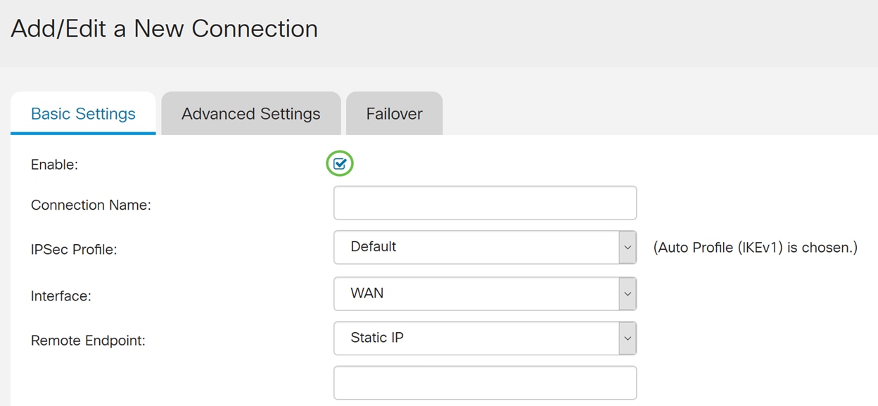
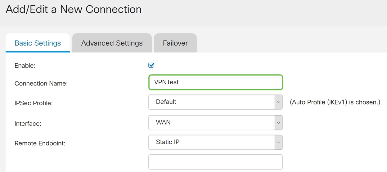
Step 5. Enter a connection name for the VPN tunnel. This description is for reference purposes and does not have to match the name used at the other end of the tunnel.
In this example, we will be entering VPNTest as our connection name.
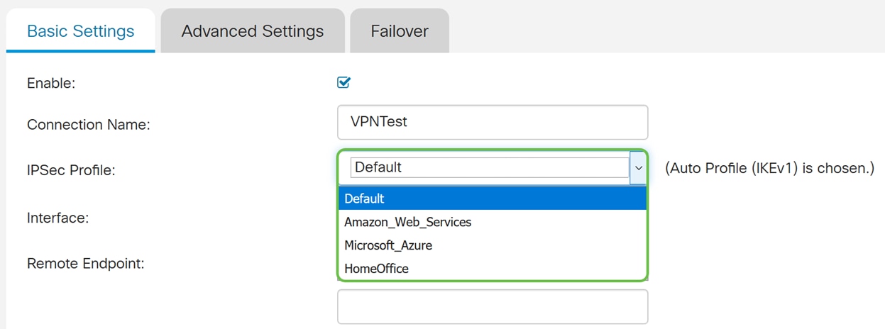
Step 6. If you have created a new IPsec profile or want to use a premade one (Amazon_Web_Services, Microsoft_Azure), select the IPsec profile that you want to use for the VPN. The Default – Auto Profile is chosen by default. IPsec profile is the central configuration in IPsec that defines the algorithms such as encryption, authentication, and Diffie-Hellman (DH) group for Phase I and Phase II negotiation.
For this example, we will be selecting HomeOffice as our IPsec profile.
Note: If you want to learn more about creating an IPsec profile, please see the article: Configuring IPSec Profiles (Auto Keying Mode) on the RV160 and RV260.
Step 7. In the Interface field, select the interface used for the tunnel. In this example, we will be using WAN as our interface.
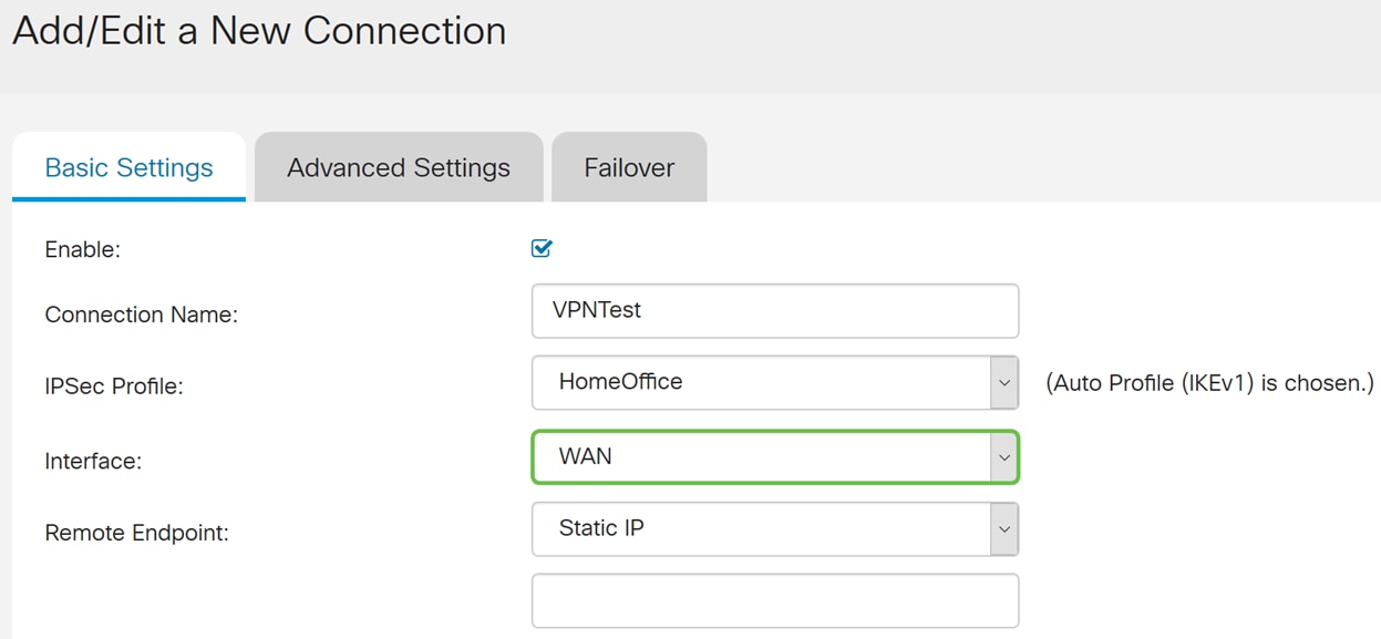
Step 8. Select either Static IP, Fully Qualified Domain Name (FQDN), or Dynamic IP for the Remote Endpoint. Enter in the IP address or FQDN of the remote endpoint based on your selection.
We have selected Static IP and entered in our remote endpoint IP address.

Configuring IKE Authentication Method
Step 1. Select either Pre-shared Key or Certificate. For this demonstration, we will be selecting Pre-shared Key as our IKE authentication method.
IKE peers authenticate each other by computing and sending keyed hash of data that includes the pre-shared key. If the receiving peer is able to create the same hash independently using its pre-shared key, it knows that both peers must share the same secret, thus authenticating the other peer. Pre-shared keys do not scale well because each IPsec peer must be configured with the pre-shared key of every other peer with which it establishes a session.
The digital certificate is a package that contains information such as a certificate bearer’s identify: name or IP address, the certificate’s serial number, the certificate’s expiration date, and a copy of certificate bearer’s public key. The standard digital certificate format is defined in the X.509 specification. X.509 version 3 defines the data structure for certificates. If you have selected Certificate, make sure your signed certificate is imported in Administration > Certificate. Select the certificate from the drop-down list for both local and remote.
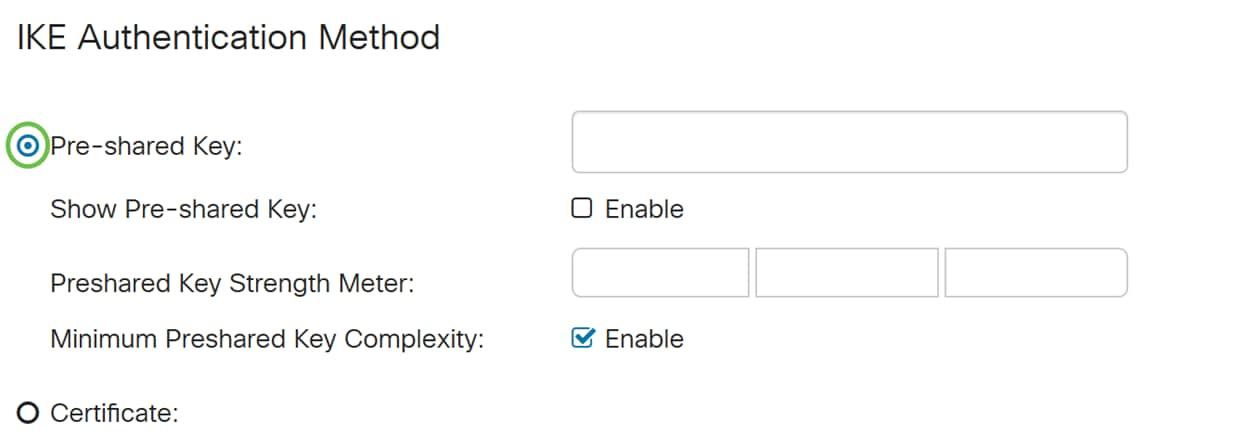
Step 2. In the Pre-shared Key field, enter in a pre-shared key.
Note: Make sure the remote router uses the same pre-shared key.
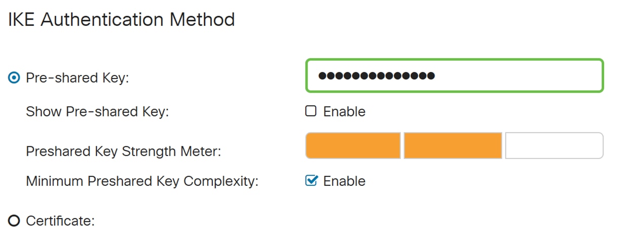
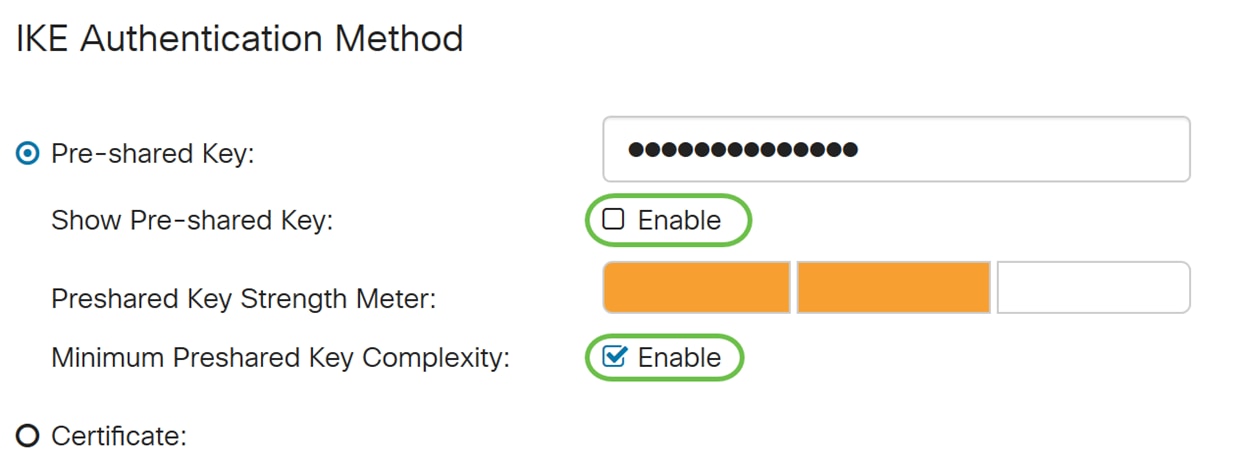
Step 3. Check the Enable checkbox if you would like to display the pre-shared key. The Preshared Key Strength Meter shows the strength of the pre-shared key through colored bars. Check Enable to enable the minimum pre-shared key complexity. Then, skip to For Local Group Setup section.
For Local Group Setup
Step 1. Select Local WAN IP, IP Address, Local FQDN, or Local User FQDN from the drop-down list. Enter the identifier name or IP Address based on your selection. If you have selected Local WAN IP, the WAN IP address of your router should automatically be entered.

Step 2. For the Local IP Type, Select Subnet, Single, Any, IP Group, or GRE Interface from the drop-down list.
In this example, Subnet was chosen.
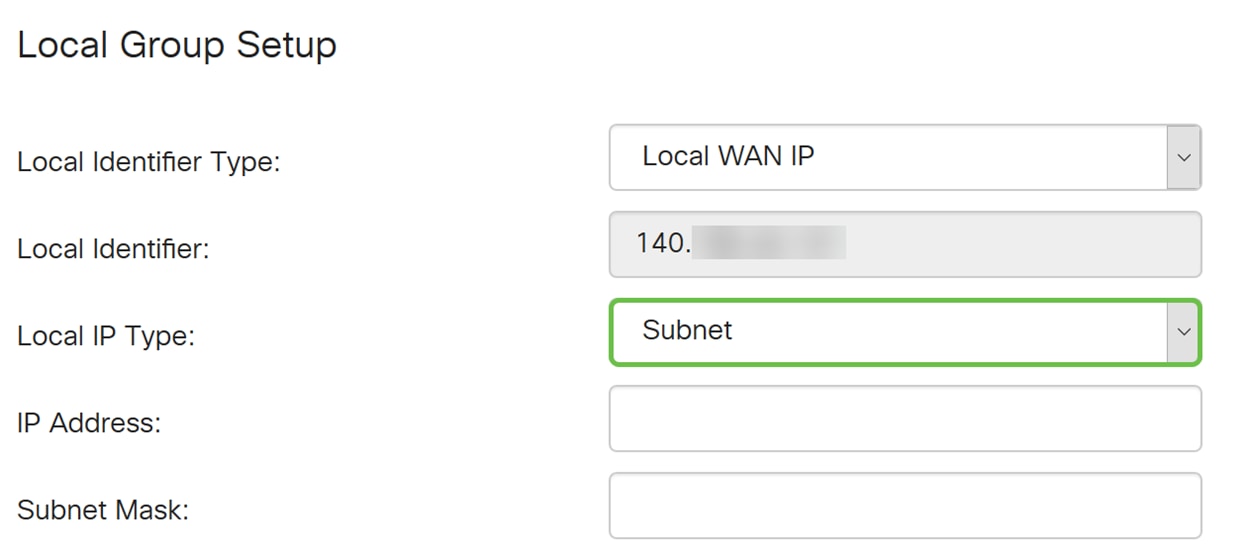
Step 3. Enter the IP address of the device that can use this tunnel. Then enter the subnet mask.
For this demonstration, we will be entering 192.168.2.0 as our local IP address and 255.255.255.0 for the subnet mask.

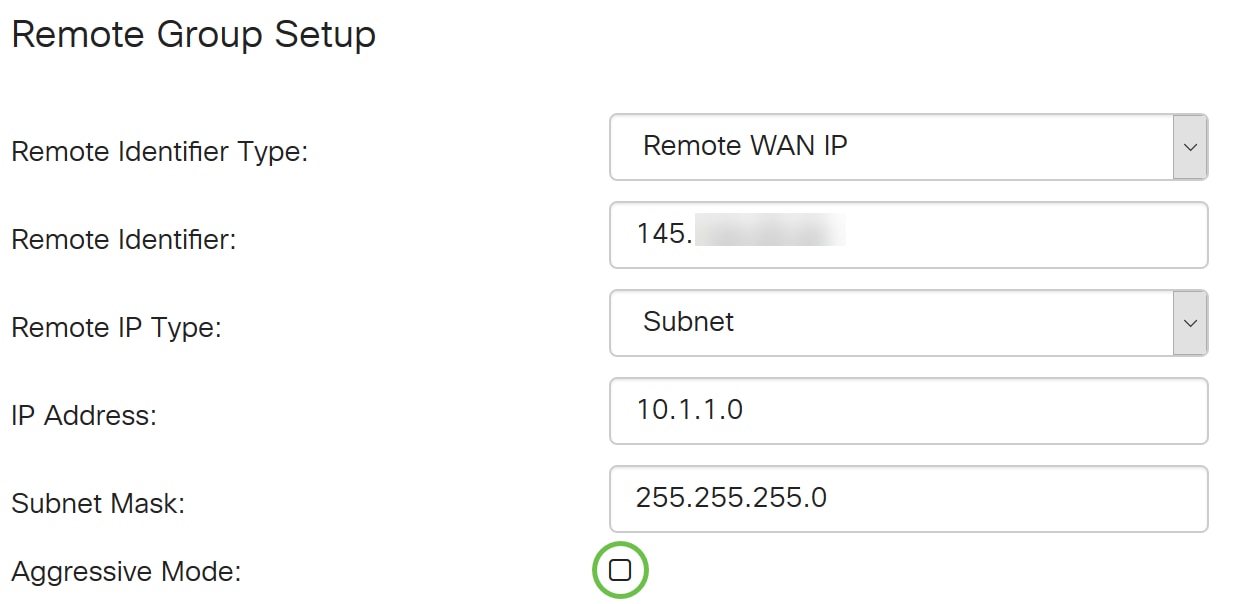
Remote Group Setup
Step 1. Select Remote WAN IP, Remote FQDN, or Remote User FQDN from the drop-down list. Enter the identifier name or IP Address based on your selection.
We have selected Remote WAN IP as our Remote Identifier Type and entered in the IP address of the remote router.
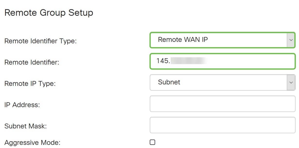
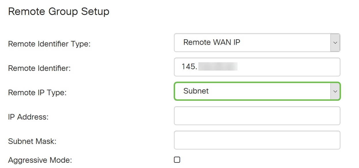
Step 2. Select Subnet, Single, Any, IP Group from the Remote IP Type drop-down list.
In this example, we will be selecting Subnet.
Note: If you have selected IP Group as your remote IP type, a popup window to create a new IP group will appear.
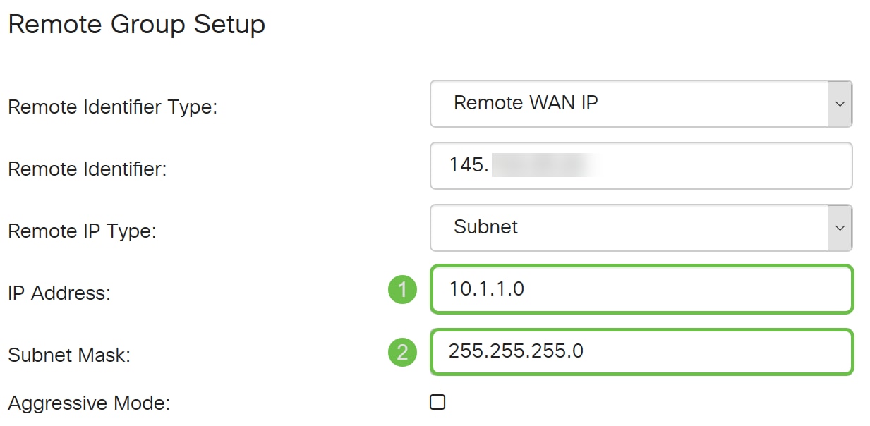
Step 3. Enter the remote local IP address and subnet mask of the device that can use this tunnel.
We have entered 10.1.1.0 for the remote local IP address that can use this tunnel and the subnet mask of 255.255.255.0.
Step 4. Check the box to enable aggressive mode. Aggressive mode is when the negotiation for IKE SA is compressed into three packets with all the SA required data to be passed by the initiator. The negotiation is quicker but they have a vulnerability of exchange identities in clear text.
In this example, we will leave it unchecked.
Note: Additional information for main mode vs aggressive mode, please see: Main Mode Vs Aggressive Mode
Step 5. Click Apply to create a new Site-to-Site VPN connection.

Conclusion
You should now have successfully added a new Site-to-Site VPN connection for your local router. You would need to configure your remote router (Router B) using the reverse information.
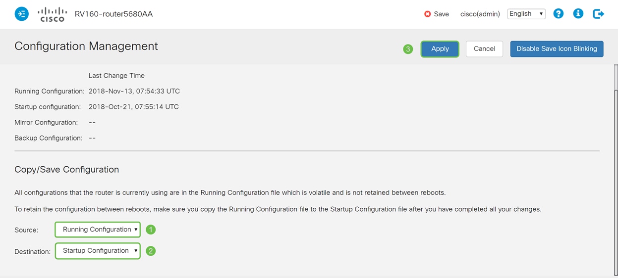
All configuration that the router is currently using are in the Running Configuration file which is volatile in the sense that it is not retained between reboots.
Step 1. At the top of the page, click the Save button to navigate to the Configuration Management to save your running configuration to the startup configuration. This is to retain the configuration between reboots.
Step 2. In the Configuration Management, make sure the Source is Running Configuration and the Destination is Startup Configuration. Then press Apply to save your running configuration to the startup configuration. All configuration that the router is currently using are in the Running Configuration file which is volatile and is not retained between reboots. Copying the Running Configuration file to the Startup Configuration file will retain all the configuration between reboots.
 Feedback