Configure DVTI with Multi-SA on Secure Firewall
Available Languages
Download Options
Bias-Free Language
The documentation set for this product strives to use bias-free language. For the purposes of this documentation set, bias-free is defined as language that does not imply discrimination based on age, disability, gender, racial identity, ethnic identity, sexual orientation, socioeconomic status, and intersectionality. Exceptions may be present in the documentation due to language that is hardcoded in the user interfaces of the product software, language used based on RFP documentation, or language that is used by a referenced third-party product. Learn more about how Cisco is using Inclusive Language.
Introduction
This document describes how to configure a DVTI on a Cisco Secure Firewall (Hub), with multiple remote extranet devices (spokes).
Background
Dynamic Virtual Tunnel Interfaces
Dynamic Virtual Tunnel Interfaces (DVTI) can provide highly secure and scalable connectivity for remote-access Virtual Prive Networks (VPN).
DVTIs can be used for both the Hub and Spoke configuration. The tunnels provide an on-demand separate virtual access interface for each VPN session.
1. The spoke initiates an IKE exchange request with the hub for a VPN connection.
2. The hub authenticates the spoke.
3. The Cisco Secure Fireawall Management Centerassigns a dynamic virtual template on the hub.
4. The virtual template dynamically generates a virtual access interface on the hub. This interface is unique for the VPN session per spoke.
5. The hub establishes a dynamic VTI tunnel with the spoke throuh the virtual access interface.
6. The hub and spoke exchange traffic over the tunnel with dynamic routing protocols (BGP/OSPF/EIGRP) or with protected networks feature (Multiple-Security Assosiations VTI).
7. Dynamic VTIs function like any other interface so that you can apply QoS, firewall rules, routing protocols and other features as soon as the tunnel is active.
8. A single DVTI is created at the HUB device and multiple Static Tunnel Interfaces for multiple remote/spoke sites.

Note: Cisco Secure Firewall added support fot DVTI on version 7.3 and currently it only supports one single DVTI as per Cisco bug ID CSCwe13781. Only registered Cisco users can access internal Cisco tools and information.
Multiple Security Asssosiation VTI feature was implemented in order to support compatibility between route based VPN and policy based VPN systems,
Prerequisites
- Have at least two Cisco Secure Firewall devices already registered with the Cisco Secure Firewall Management Center with basic routing configuration to work as one hub and one spoke-1 respectively with one Loopback interface on each device to simulate local networks on premises of 192.168.5.0/24 (hub) and remote local network of 192.168.6.0/24 (spoke-1).
- Have one ASA in place with basic routing configuration and IKEv2 support to work as a spoke-2 with one Loopback interface pre configured to simulate remote local network of 192.168.7.0/24.
- Have one Cisco IOS / Cisco IOSXE router with basic routing configuration and IKEV2 support to work as a spoke-3 with one Loopback interface pre configured to simulate remote local network of 192.168.8.0/24.
Requirements
- Knowledge on VPN technologies and IKEv2 protocol.
- Knowledge on Cisco Secure Firewall Management Center GUI (FMC) navigation and configuration for Cisco Secure Firewall devices.
- Basic configuration knowledge on Cisco IOS-XE devices.
- Basic IPV4 routing concepts.
Note: The information in this document was created from the devices in a specific lab environment. All of the devices used in this document started with a cleared (default) configuration. If your network is live, ensure that you understand the potential impact of any command.
Components Used
The information in this document is based on these software versions:
- Cisco Secure Firewall Management Center (FMC) 7.3 or later.
- Cisco Secure Firewall 7.3 or later.
- ASAv 9.20 or later
- Cisco CSR
Note: The information in this document was created from the devices in a specific lab environment. All of the devices used in this document started with a cleared (default) configuration. If your network is live, ensure that you understand the potential impact of any command.
Configure
Network Diagram
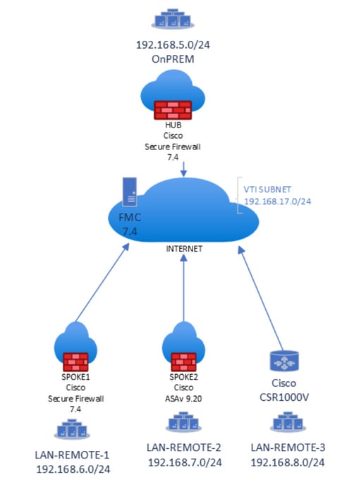
Note: All local and remote subnets are simulated with Loopback interfaces previously configured on each device.
Configurations
1.Log in into FMC GUI with administrator credentials.
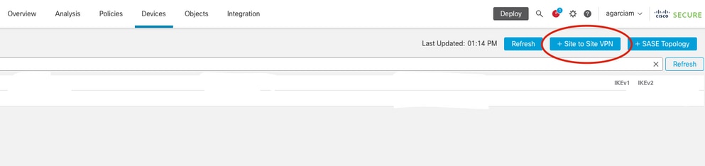
2. From the FMC dashboard view, go to Devices and click on Site To Site under VPN options.

3.From the Site to Site dashboard, click on + Site to Site VPN to create a new Site to Site topology.
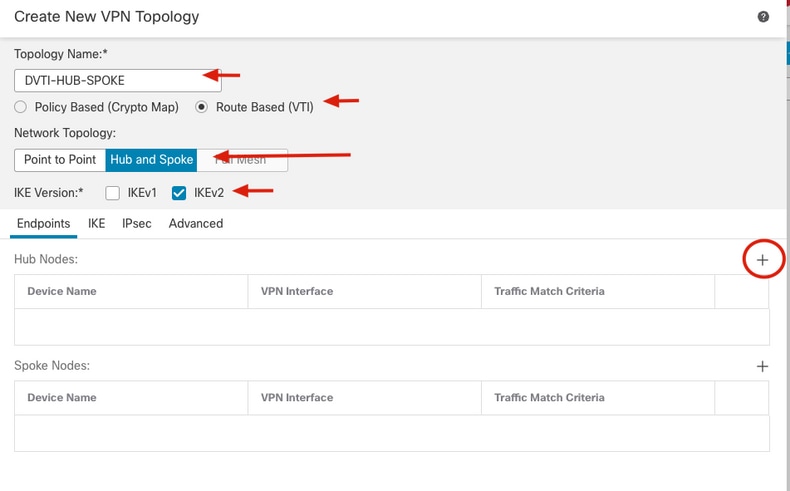
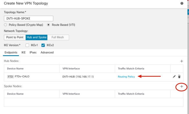
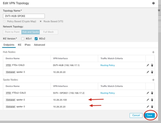
4. From the Create New VPN Topology menu, specify the new name and select Route Based (VTI) as the VPN type of the new topology, check IKEv2 protocol from the IKE Version options, select Hub and Spoke under the Network Topology settings and click on the + icon from the Hub Nodes section to designate a new Hub device.
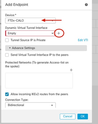
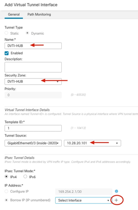
5. From the Add Endpoint window, select the device that works as the hub and click on the + icon next to Dynamic Virtual Tunnel Interface dropdown menu to create a new DVTI.
6. From the Add Virtual Tunnel Interface menu, specify the name of the new Tunnel interface, assign it to the desired Security Zone, select the Tunnel Source with its IP and click on the + icon under the IP Address configuration in order to create a new Loopback interface next to the Borrow IP option.
Cisco recommends to configure the Borrowed IP for the dynamic interface from a Loopback interface.
Note: Tunnel source interface needs to be routable and able to reach remote spokes peer IPs
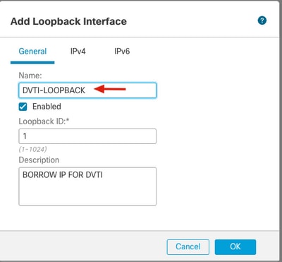
7. From the Add Loopback Interface window, specify the name of the interface with its ID and go to IPv4 tab.
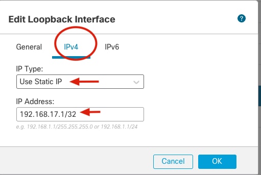
8. From the IPv4 tab select Use Static IP under the IP Type option from the dropdown menu and specify the IP Address that belongs to the DVTI and click OK.
Note: Hub DVTI has an IP Address of 192.168.17.1/32.
9. From the Add Virtual Tunnel Interface menu, new Loobpack is displayed under the dropdown menu, select it and click OK.
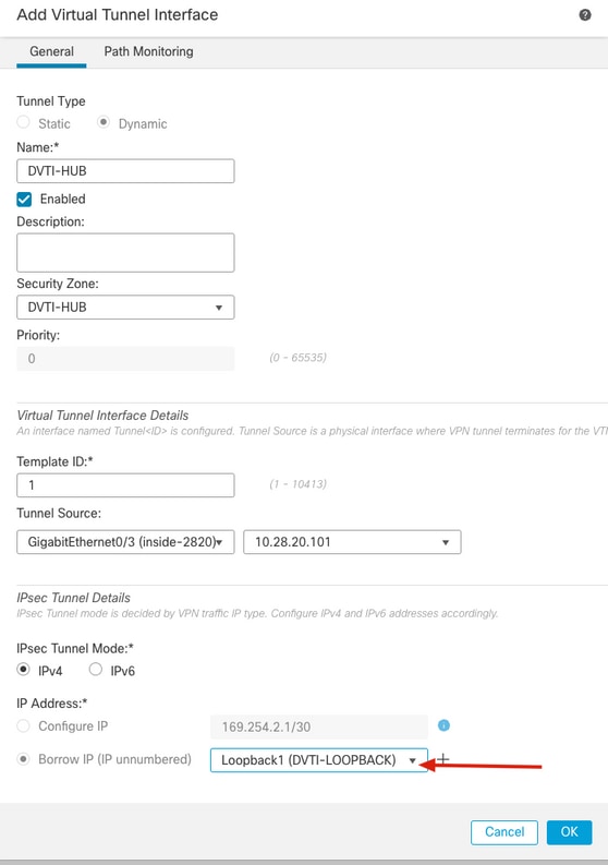
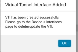
10. A Virtual Tunnel Interface Added window is prompted that indicates the new DVTI has been created, click Ok and continue.
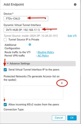
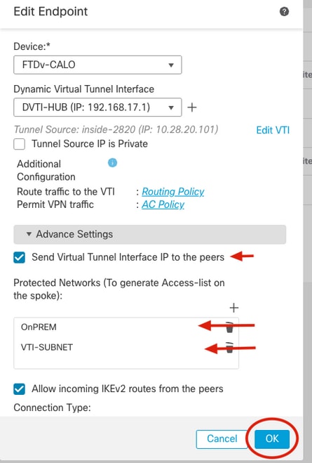
11. From the Add Endpoint window, new DVTI is displayed under Dynamic Virtual Tunnel Interface dropdown bar, select it, check the Send Virtual Tunnel Interface IP to peers box option along with the Allow incoming IKEv2 routes from the peers option and click on the + next to the Protected Networks settings in order to specify the networks behind the hub device.
Note: In this example, a second loopback interface on the hub simulates a host in the local OnPREM subnet as part of the protected network with an IP Address of 192.168.5.1/24.
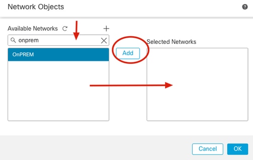
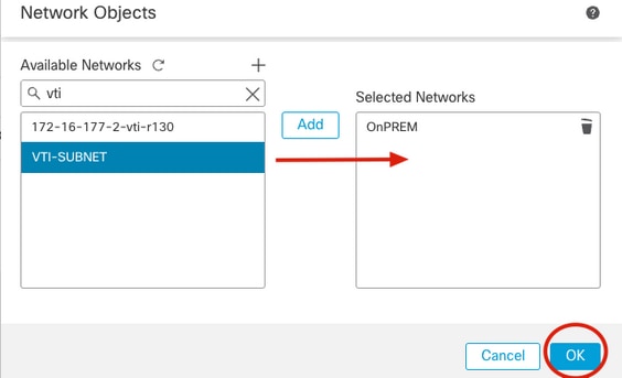
12. On the Available Networks section, identify the subnet that simulates the local protected network as well as the DVTI subnet (192.168.17.0/24) and click on Add and then OK to apply the change.
Note: In this article a network object has been preconfigured as OnPREM with the 192.168.17.0/24 network. DVTI subnet needs to be added in order to protect traffic that is sourced from the tunnel interfaces.
13. Confirm the new protected network object has been added and click OK.
14. Confirm the new hub device has been added under the Hub Nodes section and click on the + next to the Spoke Nodes section to add a new endpoint as a remote spoke-1.
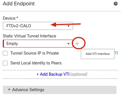
15. From the Add Endpoint window, select the device that runs as the spoke-1 and click on the + icon next to Static Virtual Tunnel Interface dropdown menu to create a new SVTI.
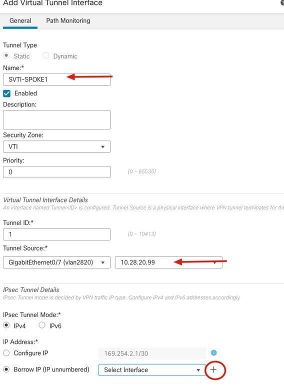
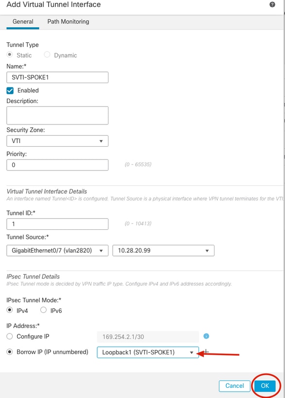
16. From the Add Virtual Tunnel Interface menu, specify the name of the new Tunnel interface, assign it to the desired Security Zone, select the Tunnel Source with its IP and click on the "+" icon under the IP Address configuration in order to create a new Loopback interface next to the Borrow IP option.
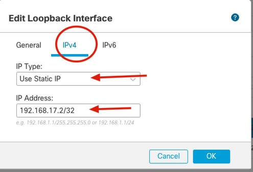
17. From the Add Loopback Interface window, specify the name of the interface with its ID and go to IPv4 tab.
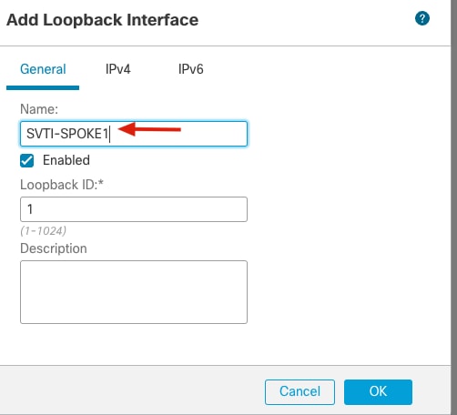
18. From the IPv4 tab select Use Static IP under the IP Type option from the dropdown menu and specify the IP Address that belongs to the SVTI and click OK.
Note: Spoke-1 SVTI has an IP Address of 192.168.17.2/32.
19. From the Add Virtual Tunnel Interface menu, new Loobpack is displayed under the dropdown menu, select it and click OK.
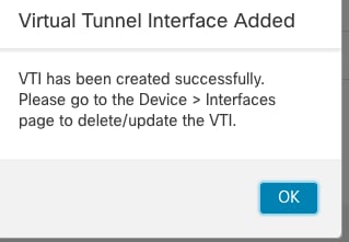
20. A Virtual Tunnel Interface Added window is prompted that indicates the new DVTI has been created, click Ok and continue.
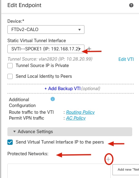
21. From the Add Endpoint window, new SVTI is displayed under StaticVirtual Tunnel Interface dropdown bar, select it, check the Send Virtual Tunnel Interface IP to peers option along with the Allow incoming IKEv2 routes from the peers option and click on the "+" next to the Protected Networks settings in order to specify the networks behind the spoke device.
Note: In this example, a second Loopback interface on the spoke-1 simulates a host in the remote network of 192.168.6.1/24.
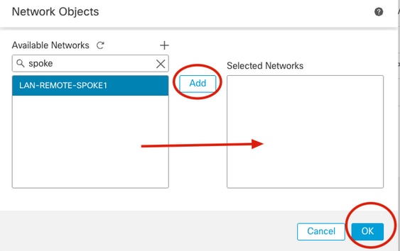
22. On the Available Networks section, identify the remote protected network as well as the VTI subnet (192.168.17.0/24) and click on Add and then OK to apply the change.
Note: SVTI subnets needs to be added in order to protect, traffic that is sourced with tunnel interfaces.
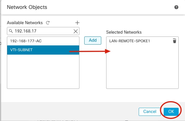
23. Confirm the new protected network object has been added and click OK.
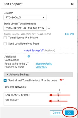
24. Confirm both hub and spoke nodes have been added to the new topology.
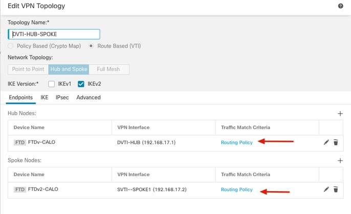
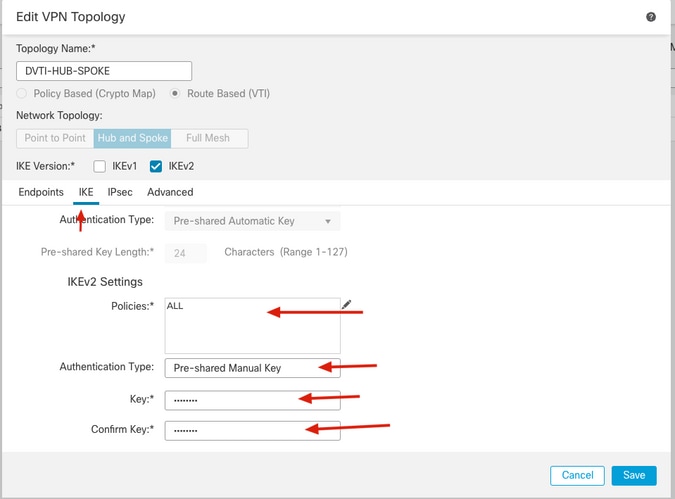
25. Go to IKE tab and specify the desired algorithms under "KEv2 Settings, select the Authentication Type with its attributes.
Note: In this article manual pre-shared key is used for authentication.
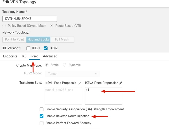
26. Go to IPsec tab, specify the desired algorithms under IKEv2 IPsec Proposals settings and check the Enable Reverse Route Injection option and go back to Endpoints tab.
Note: When no dynamic routing protocol is used Reverse Route Injection needs to be enabled in order to advertise OnPREM and remote protected networks across the tunnel between hub and all spokes.
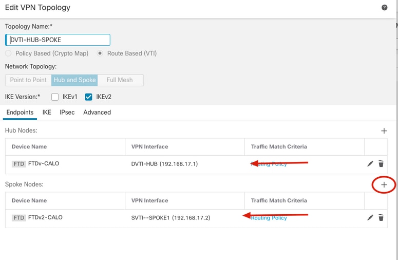
27. Add one more extranet spoke-2, click on the + icon from the Endpoints tab.
28. From the Add Endpoint window Select Extranet from the dropdown menu under Device, specify the device name from spoke-2 and its peer IP Address and click OK.
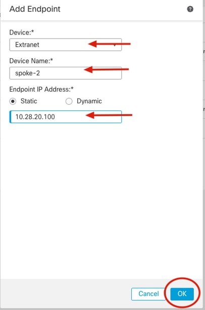
29. Repeat steps 27 and 28 to add a new spoke-3 from the extranet.
Note: In this article CSRv1000 device is be used as the spoke-3.
30. Confirm new extrane spokes have been added to the topology and click on Save.
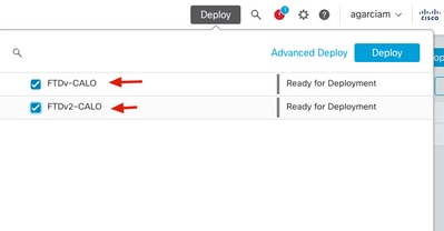
31. Deploy configuration on both Cisco Secure Firewall devices.
Final configurations
Cisco Secure Firewall Hub configuration
crypto ikev2 policy 100
 encryption aes-256 aes
 integrity sha512 sha384 sha256 sha
 group 21 20 19 14
 prf sha512 sha384 sha256 sha
 lifetime seconds 86400

crypto ikev2 enable inside-2820

crypto ipsec ikev2 ipsec-proposal CSM_IP_1
 protocol esp encryption aes-256 aes
 protocol esp integrity sha-512 sha-384 sha-256 sha-1
crypto ipsec profile FMC_IPSEC_PROFILE_2
 set ikev2 ipsec-proposal CSM_IP_1

interface Virtual-Template1 type tunnel
 nameif DVTI-HUB
 ip unnumbered DVTI-LOOPBACK
 tunnel source interface inside-2820
 tunnel mode ipsec ipv4
 tunnel protection ipsec profile FMC_IPSEC_PROFILE_2

tunnel-group 10.28.20.99 type ipsec-l2l
tunnel-group 10.28.20.99 general-attributes
 default-group-policy .DefaultS2SGroupPolicy
tunnel-group 10.28.20.99 ipsec-attributes
 virtual-template 1
 ikev2 remote-authentication pre-shared-key *****
 ikev2 local-authentication pre-shared-key *****
 ikev2 route set interface
tunnel-group 10.28.20.100 type ipsec-l2l
tunnel-group 10.28.20.100 general-attributes
 default-group-policy .DefaultS2SGroupPolicy
tunnel-group 10.28.20.100 ipsec-attributes
 virtual-template 1
 ikev2 remote-authentication pre-shared-key *****
 ikev2 local-authentication pre-shared-key *****
 ikev2 route set interface
tunnel-group 10.28.20.20 type ipsec-l2l
tunnel-group 10.28.20.20 general-attributes
 default-group-policy .DefaultS2SGroupPolicy
tunnel-group 10.28.20.20 ipsec-attributes
 virtual-template 1
 ikev2 remote-authentication pre-shared-key *****
 ikev2 local-authentication pre-shared-key *****
 ikev2 route set interface
Cisco Secure Firewall Spoke-1 configuration
crypto ikev2 policy 10
 encryption aes-256 aes
 integrity sha512 sha384 sha256 sha
 group 21 20 19 14
 prf sha512 sha384 sha256 sha
 lifetime seconds 86400
crypto ikev2 enable vlan2820

crypto ipsec ikev2 ipsec-proposal CSM_IP_2
 protocol esp encryption aes-256 aes
 protocol esp integrity sha-512 sha-384 sha-256 sha-1
crypto ipsec profile FMC_IPSEC_PROFILE_2
 set ikev2 ipsec-proposal CSM_IP_2
 set reverse-route

access-list CSM_IPSEC_ACL_2 extended permit ip 192.168.6.0 255.255.255.0 192.168.5.0 255.255.255.0
access-list CSM_IPSEC_ACL_2 extended permit ip 192.168.6.0 255.255.255.0 192.168.17.0 255.255.255.0
access-list CSM_IPSEC_ACL_2 extended permit ip 192.168.17.0 255.255.255.0 192.168.5.0 255.255.255.0
access-list CSM_IPSEC_ACL_2 extended permit ip 192.168.17.0 255.255.255.0 192.168.17.0 255.255.255.0

interface Tunnel1
 nameif SVTI--SPOKE1
 ip unnumbered SVTI-SPOKE1
 tunnel source interface vlan2820
 tunnel destination 10.28.20.101
 tunnel mode ipsec ipv4
 tunnel protection ipsec profile FMC_IPSEC_PROFILE_2
 tunnel protection ipsec policy CSM_IPSEC_ACL_2
tunnel-group 10.28.20.101 type ipsec-l2l
tunnel-group 10.28.20.101 ipsec-attributes
 ikev2 remote-authentication pre-shared-key *****
 ikev2 local-authentication pre-shared-key *****
 ikev2 route set interface
Note: Cisco ASAv spoke-2 configuration omited as it is the same as configuration for spoke-1
Cisco CSRv1000 spoke-3 configuration
crypto ikev2 proposal all
 encryption aes-cbc-256 aes-cbc-128 aes-cbc-192
 integrity sha256 sha1 sha384 sha512
 group 20 14 15 21 24
crypto ikev2 policy test
 match address local 10.28.20.20
 proposal all
crypto ikev2 authorization policy default
 route set interface Tunnel100
 route set remote ipv4 192.168.8.0 255.255.255.255

crypto ikev2 profile vti
 match identity remote any
 identity local address 10.28.20.20
 authentication remote pre-share key cisco123
 authentication local pre-share key cisco123
 no config-exchange request
aaa authorization group psk list default default

crypto ipsec transform-set aes256sha256 esp-aes 256 esp-sha256-hmac
 mode tunnel
crypto ipsec profile vti
 set security-association lifetime seconds 120
 set transform-set aes256sha256
 set ikev2-profile vti
 reverse-route

interface Tunnel100
 ip address 192.168.17.4 255.255.255.0
 tunnel source GigabitEthernet1
 tunnel mode ipsec ipv4
 tunnel destination 10.28.20.101
 tunnel protection ipsec policy ipv4 ipsec-policy
 tunnel protection ipsec profile vti
ip access-list extended ipsec-policy
 10 permit ip 192.168.8.0 0.0.0.255 192.168.5.0 0.0.0.255
 20 permit ip 192.168.8.0 0.0.0.255 192.168.17.0 0.0.0.255
 30 permit ip 192.168.17.0 0.0.0.255 192.168.5.0 0.0.0.255
 40 permit ip 192.168.17.0 0.0.0.255 192.168.17.0 0.0.0.255
Verify
From Hub routing table, we see the routes from all spokes received over the virtual templates as soon as IKEv2 tunnels come up.
firepower# show route


C        192.168.5.0 255.255.255.0 is directly connected, OnPrem-Network
L        192.168.5.1 255.255.255.255 is directly connected, OnPrem-Network
V        192.168.6.0 255.255.255.0
           connected by VPN (advertised), DVTI-HUB_va146
V        192.168.7.0 255.255.255.0
           connected by VPN (advertised), DVTI-HUB_va105
V        192.168.8.0 255.255.255.0
           connected by VPN (advertised), DVTI-HUB_va155
V        192.168.17.0 255.255.255.0
           connected by VPN (advertised), DVTI-HUB_va146
C        192.168.17.1 255.255.255.255 is directly connected, DVTI-LOOPBACK
V        192.168.17.2 255.255.255.255
           connected by VPN (advertised), DVTI-HUB_va146
V        192.168.17.3 255.255.255.255
           connected by VPN (advertised), DVTI-HUB_va105
V        192.168.17.4 255.255.255.255
           connected by VPN (advertised), DVTI-HUB_va155
S        192.168.19.100 255.255.255.255 [1/0] via 10.28.20.20, inside-2820
Hub is now able to ping all SVTI spoke interface sourced from DVTI.
Note: "show crypto ipsec" sa command displays the multiple IPSec SA created when Reverse Route Injection with protected networks is applied.
firepower# ping 192.168.17.2
Type escape sequence to abort.
Sending 5, 100-byte ICMP Echos to 192.168.17.2, timeout is 2 seconds:
!!!!!
Success rate is 100 percent (5/5), round-trip min/avg/max = 1/4/10 ms
firepower#   ping 192.168.17.3
Type escape sequence to abort.
Sending 5, 100-byte ICMP Echos to 192.168.17.3, timeout is 2 seconds:
!!!!!
Success rate is 100 percent (5/5), round-trip min/avg/max = 1/2/10 ms
firepower#   ping 192.168.17.4
Type escape sequence to abort.
Sending 5, 100-byte ICMP Echos to 192.168.17.4, timeout is 2 seconds:
!!!!!
Success rate is 100 percent (5/5), round-trip min/avg/max = 1/1/1 ms
firepower# show crypto ipsec sa | i cap|iden
local ident (addr/mask/prot/port): (192.168.17.0/255.255.255.0/0/0)
      remote ident (addr/mask/prot/port): (192.168.17.0/255.255.255.0/0/0)
      #pkts encaps: 15, #pkts encrypt: 15, #pkts digest: 15
      #pkts decaps: 15, #pkts decrypt: 15, #pkts verify: 15
     #PMTUs sent: 0, #PMTUs rcvd: 0, #decapsulated frgs needing reassembly: 0
      current outbound spi: 5A68524C
      current inbound spi : DDF6D48F
      spi: 0xDDF6D48F (3723941007)
      spi: 0x5A68524C (1516786252)
Hub is now able to ping REMOTE-LAN networks behind all spokes sourced from OnPREM host.
Note: "show crypto ipsec" sa command displays the multiple IPSec SA created when Reverse Route Injection with protected networks is applied.
firepower# ping OnPrem-Network 192.168.6.1
Type escape sequence to abort.
Sending 5, 100-byte ICMP Echos to 192.168.6.1, timeout is 2 seconds:
!!!!!
Success rate is 100 percent (5/5), round-trip min/avg/max = 1/4/10 ms
firepower# ping OnPrem-Network 192.168.7.1
Type escape sequence to abort.
Sending 5, 100-byte ICMP Echos to 192.168.7.1, timeout is 2 seconds:
!!!!!
Success rate is 100 percent (5/5), round-trip min/avg/max = 1/2/10 ms
firepower# ping OnPrem-Network 192.168.8.1
Type escape sequence to abort.
Sending 5, 100-byte ICMP Echos to 192.168.8.1, timeout is 2 seconds:
!!!!!
Success rate is 100 percent (5/5), round-trip min/avg/max = 1/1/1 ms

firepower# show crypto ipsec sa | i cap|iden
local ident (addr/mask/prot/port): (192.168.5.0/255.255.255.0/0/0)
      remote ident (addr/mask/prot/port): (192.168.6.0/255.255.255.0/0/0)
      #pkts encaps: 5, #pkts encrypt: 5, #pkts digest: 5
      #pkts decaps: 5, #pkts decrypt: 5, #pkts verify: 5
local ident (addr/mask/prot/port): (192.168.5.0/255.255.255.0/0/0)
      remote ident (addr/mask/prot/port): (192.168.7.0/255.255.255.0/0/0)
      #pkts encaps: 5, #pkts encrypt: 5, #pkts digest: 5
      #pkts decaps: 5, #pkts decrypt: 5, #pkts verify: 5
local ident (addr/mask/prot/port): (192.168.5.0/255.255.255.0/0/0)
      remote ident (addr/mask/prot/port): (192.168.8.0/255.255.255.0/0/0)
      #pkts encaps: 5, #pkts encrypt: 5, #pkts digest: 5
      #pkts decaps: 5, #pkts decrypt: 5, #pkts verify: 5
Troubleshoot
To troubleshoot IKEv2 and IPSEC process use the debug commands below:
ASA/Cisco Secure Firewall

debug crypto ikev2 protocol 255
debug crypto ikev2 platform 255
debug crypto ipsec

CSR

debug crypto ikev2
debug crypto ipsec
Revision History
| Revision | Publish Date | Comments |
|---|---|---|
1.0 |
03-Apr-2023 |
Initial Release |
Contributed by Cisco Engineers
- Alan Omar Garcia MarchanCisco TAC Engineer
 Feedback
Contact Cisco
- Open a Support Case

- (Requires a Cisco Service Contract)