Sandvik and Cisco Digital Mine Solution White Paper
Available Languages
Bias-Free Language
The documentation set for this product strives to use bias-free language. For the purposes of this documentation set, bias-free is defined as language that does not imply discrimination based on age, disability, gender, racial identity, ethnic identity, sexual orientation, socioeconomic status, and intersectionality. Exceptions may be present in the documentation due to language that is hardcoded in the user interfaces of the product software, language used based on RFP documentation, or language that is used by a referenced third-party product. Learn more about how Cisco is using Inclusive Language.
Sandvik Group
Sandvik is a high-tech global engineering group offering products and services that enhance customer productivity, profitability, and safety. Sandvik holds world-leading positions in selected areas – tools and tooling systems for metal cutting; equipment and tools, services, and technical solutions for the mining industry and rock excavation within the construction industry; products in advanced stainless steels and special alloys as well as products for industrial heating. In 2020, the Group had approximately 37,000 employees and revenues of about 86 billion SEK in more than 160 countries within continuing operations.
Sandvik Mining and Rock Solutions
Sandvik Mining and Rock Solutions is a business area within the Sandvik Group and a global leading supplier of equipment and tools, parts, service and technical solutions for the mining and construction industries. Application areas include rock drilling, rock cutting, loading and hauling, tunnelling and quarrying. In 2020, sales were approximately 37 billion SEK, with about 12,500 employees within continuing operations.
Sandvik Mining and Rock Solutions is a world leader in mining automation, implementing digital mining solutions for more than two decades. Sandvik’s AutoMine® and OptiMine® solutions are used in more than 60 mines around the world. My Sandvik collects data from over 2000 Sandvik equipment globally.
The AutoMine® product family allows customers to scale up mining automation at their own pace. AutoMine® covers all aspects of equipment automation, from remote and autonomous operation of a single piece of equipment, to multi-machine control and full-fleet automation using automatic mission and traffic control capabilities.
OptiMine® is the most comprehensive suite of digital tools for analyzing and optimizing underground hard rock mining production and processes. It integrates all relevant data of all assets and people, including Sandvik and non-Sandvik equipment, into one source, delivering real-time descriptive and predictive insights to improve operations. OptiMine® is open and scalable, giving customers the flexibility to build at their own speed and incorporate other equipment, systems, and networks.
My Sandvik connects the Sandvik fleet of mine operations to a service that enables them to access vital information of their equipment through the MySandvik customer portal. Besides providing access for keeping track of the fleet performance and preventive services information, the My Sandvik portal can be used to request quotations and place orders any time they are needed.
The Sandvik and Cisco partnership seeks to accelerate the digitalization of the mining industry and extend and enhance the Sandvik offering and facilitate integration of Cisco® technology within mining operations. With its global coverage, both from a technology perspective and a commercial perspective (sales and support), Cisco is in a unique position to collaborate with Sandvik in this space to bridge the gap between Operations Technology (OT) and Information Technology (IT).
The following key philosophies underpin this document:
● Open architecture:
◦ Architectures should not be closed to specific vendor equipment
◦ Architectures are developed from standards-based work
◦ Network equipment should not be restricted
◦ Network security (physical and cyber) should be increased
● Compliance with standards:
◦ Standards underpin the architectures proposed within this document
◦ Where standards are developing, an industry “best practice” view has been taken
◦ Interoperability is a key requirement of any future network
● Flexibility:
◦ Proposed solutions or designs should be flexible to adapt to local conditions (such as remote locations)
◦ Architectures should allow both existing legacy devices and protocols to be supported and enable newer Ethernet-based technologies
● Future readiness:
◦ Technologies proposed should have a long-term life span
◦ A single technology platform should be used that allows new services to be deployed with ease (virtualization at the network and application level)
◦ The platform should enable IPv6 to be deployed at a later date
● OpEx reduction:
◦ Migrate away from proprietary hardware and software
◦ Use off-the-shelf vendor technologies
◦ Reduce complexity
◦ Simplify network management
◦ Use a modular design to enable easy expansion
◦ Replace obsolete technologies
◦ Enable condition-based maintenance
My Sandvik Digital Service solutions give you visibility into fleet utilization, productivity, safety, and health on a 24/7 basis. Once activated, the Knowledge Box™ on board your Sandvik fleet collects and transfers equipment data to the My Sandvik IoT hub. This is where gathered data is processed into easy-to-use knowledge about your fleet’s health and performance. The knowledge gained helps you to make substantial observations and prioritize actions during daily operations. The valuable services of 365 My Sandvik Digital Service Solutions can be accessed through the My Sandvik customer portal, where you can subscribe either My Sandvik Insight or My Sandvik Productivity. Role-based dashboards are available on the My Sandvik Productivity service level and contain productivity information, health and safety related alerts, and signal reports.
Network requirements
The network must provide connectivity in order to upload stored data to the My Sandvik portal. Wi-Fi connectivity can be provided at key points in the facility, but continuous coverage is not required. The loader will store asset-related data for upload to a cloud service when it has connectivity.
Sandvik OptiMine® is the most comprehensive suite of digital tools for analyzing and optimizing underground hard rock mining production and processes. It integrates all relevant data of all assets and people including Sandvik and non-Sandvik equipment into one source, delivering both real-time and predictive insights to improve operations. OptiMine® is open and scalable through the different modules, giving customers the flexibility to build at their own speed and incorporate other equipment, systems, and networks.
OptiMine® Analytics is the next generation of OptiMine® that transforms data into process improvement via predictive insights and actionable dashboards embedded into your operation management systems. OptiMine® Analytics is powered by IBM Watson IoT, a suite of Artificial Intelligence (AI) services, applications, and tools. The dashboards combine real-time data from multiple resources, calculating the Overall Equipment Efficiency (OEE) and identifying possible lost time. Predictive analytics can predict failures of major components. The solution is provided with Sandvik digital consultancy services for mining process optimization.
OptiMine® Scheduler is an efficient smart graphical scheduling and resource allocation tool for mine development, production and maintenance activities. This OptiMine® module offers a centralized platform for planning all mining operations, automatically dispatching tasks to operators underground and reporting progress and any deviations.
OptiMine® Task Management is designed to receive scheduled tasks and allow operators underground to immediately respond and adapt to any changes in their working environment. Operators can manage work tasks easily with a tablet application and take corrective actions when needed, so that resources can be used to optimize the results of the ongoing tasks.
OptiMine® Mine Visualizer provides a three-dimensional model of your mine on your screen. The entire mine can be viewed and examined both inside and outside. This improves situational awareness, as information about the mine can be easily studied and understood at a single glance.
OptiMine® Location Tracking provides accurate, real-time location data for all resources, including Sandvik and non-Sandvik equipment, as well as personnel and material flow. The data is collected locally by the location tracking unit, with no need for any additional production area infrastructure, or by tag-based location tracking method. Whether in a control room or underground in the mine, the OptiMine® Location Tracking module keeps you constantly aware of the status and location of your fleet on 3D models of the mine.
OptiMine® Drill Plan Visualizer is an easy-to-use tool for the visualization of longhole drilling and rock support. This OptiMine® module visualizes your drill plans and drilling results in a user-friendly and informative way to give the mine planning crew the necessary tools to compare drilling results to longhole drilling plans.
My Sandvik Productivity updates equipment information automatically in real time. This capability guarantees constant up-to-date awareness of the status and productivity of your Sandvik fleet. The information is presented clearly and intuitively to support fact-based decisions.
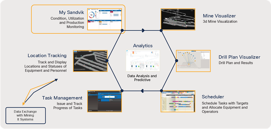
Sandvik OptiMine® Product Family
OptiMine® network requirements
IP network connectivity from mine vehicles or other assets (people, infrastructure sensors, etc.) to a local server is required. Optionally, network connectivity from a local server to a Sandvik cloud service can be used for the optional OptiMine® Analytics service.
For data gathering, network access needs to be provided at strategic locations within the mine. For the OptiMine® Location Tracking module, network connectivity is required throughout the mine.
Network connectivity from an on-premises AutoMine® network to cloud services is via the AutoMine® firewall and the customer firewall.
AutoMine® Underground for Loading and Hauling is an automation system for autonomous and tele-remote operation for a wide range of Sandvik loaders and trucks. The AutoMine® product family allows customers to scale up automation at their own pace. It covers all aspects of automation, from remote and autonomous operation of a single piece of equipment - to multi-machine control and full-fleet automation using automatic mission and traffic control capabilities. The product family consists of four different levels of solutions.
AutoMine® Tele-Remote is the entry-level package of AutoMine®. A solution for smart teleoperation, it provides a new and easy way to explore the full potential of automated Sandvik equipment while achieving the benefits of increased productivity, safety, and cost-efficiency in mining operations. It provides functionality for the teleoperation and monitoring of a single loader or truck. Without requiring advanced technical skills, it is easy to set up, operate, and maintain.
AutoMine® Lite is an automation system for a single Sandvik loader or truck and a more advanced alternative for AutoMine® Tele-Remote. The solution provides a powerful way to take advantage of the full machine performance through automation and offers substantial benefits of increased productivity, safety, and cost-efficiency in mining operations.
AutoMine® Multi-Lite is an automation system that enables each system operator to remotely control and simultaneously supervise multiple automated Sandvik underground loaders and trucks. With AutoMine® Multi-Lite, each piece of equipment completes automated missions in its own dedicated production area.
AutoMine® Fleet is a highly advanced automation system for a fleet of Sandvik underground loaders and trucks sharing the same automated production area. It provides automatic mission control and traffic management for the equipment fleet, while system operators remotely supervise the process. With AutoMine® Fleet, mining companies can take advantage of the full potential of Sandvik equipment automation and achieve outstanding benefits of increased productivity, safety, and cost-efficiency in mining operations.
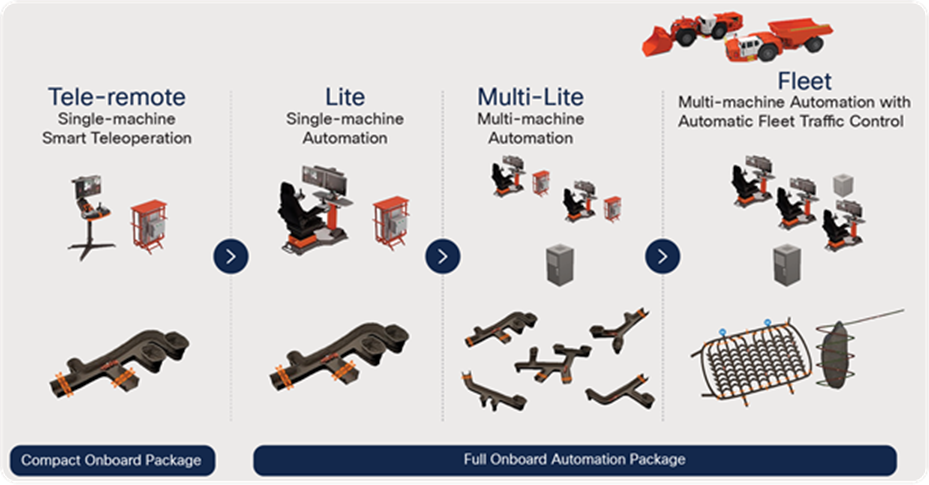
Sandvik AutoMine® L&H Product Family for underground loaders and trucks
AutoMine® network requirements
AutoMine® requires a Layer 3 IP connection from the control room to the loader computers and cameras. This is facilitated by the Cisco mine network, consisting of the components shown in the following table.
Table 1. Cisco underground mine network components
| Component |
Role |
Version |
| Cisco 3504 or 5520 Wireless Controller |
Cisco AireOS wireless LAN controller |
AireOS 8.10.122 |
| Cisco Aironet® 1572 access point |
Mine infrastructure AP (end of sale 11/20 – supported for existing deployments) |
AireOS 8.10.122 |
| Antenna: AIR-ANT2568VG-N |
Cisco 1572 dual-band omnidirectional antenna; 4 antennas recommended per AP for maximum omnidirectional performance |
2.4 and 5 GHz 6/8 dBi gain Omnidirectional |
| Cisco IW3702 access point |
Mine infrastructure AP |
AireOS 8.10.122 |
| Cisco IW3702 access point |
Vehicle workgroup bridge |
AireOS 8.10.122 |
| Antenna: AIR-ANT2547V-N |
Cisco IW3702 infrastructure AP dual-band omnidirectional antenna; 4 antennas recommended for each AP for diversity |
2.4 and 5 GHz 4/7 dBi gain Omnidirectional |
| Cisco IE 4000 Series Switches |
Mine infrastructure switch with fiber ports |
Cisco IOS® 15.2(4)EA9 (fc2) |
| Cisco Catalyst® 9300 Series Switches |
Control room distribution layer switch |
Cisco IOS XE 17.1.1 |
| Cisco Catalyst 9500 Series Switches |
Control room distribution/core layer switch |
Cisco IOS XE 17.1.1 |
| CX RF Site Survey Services offering |
Cisco Services for wireless RF site survey and post-deployment RF tuning |
N/A- |
Note: We highly recommend deploying the validated software versions listed in the table above. Versions different than the ones listed should be verified during commissioning.
Table 2. Third-party network components
| Component |
Role |
Model |
| Mobile Mark antenna for Cisco IW3702 workgroup bridge (WGB) |
Vibration-resistant antennas for the Cisco IW3702 WGB mounted on an autonomous vehicle |
Note: The referenced and validated Mobile Mark antenna is just one of the options for a vibration-resistant antenna that might be mounted on the vehicle. Other options are available. Please refer to the actual antenna make and model installed on your vehicles and adjust the antenna configuration and gain accordingly.
Cisco IE 4000 Series Switches are connected via fiber-optic cable at various points in the mine tunnels in order to provide connectivity nodes for access points and laser barriers. The switches are connected in a chain via the Gigabit Ethernet fiber-optic ports. The number of switches in the chain should take into account the total bandwidth required to service the number of loaders in operation on that section (based on the 10 Mbps dimensioning requirement per vehicle).
The predominant wired access topologies within an underground mine are a Cisco Resilient Ethernet Protocol (REP) ring or a hub-and-spoke (star) topology.
A protective cabinet with suitable power and cable entry/exit protection houses each IE 4000 Series switch. Cisco Aironet 1572 or IW3702 access points are wall or ceiling mounted along the mine tunnels and connect to the IE 4000 Series switch via a single X-code M12 copper Ethernet cable (maximum distance 100 meters). This connection to the IE 4000 Series switch provides both power (IEEE 802.3af PoE+) and a Gigabit Ethernet connection.
Two StackWise® Cisco Catalyst 9300 Series Switches provide the distribution/aggregation layer for the IE 4000 Series switches in the mine network. These are installed in the control room or at a data center. The AutoMine server top-of-the-rack switch in the control room would be connected to this aggregation layer.
Mine network topology
● The 2.4-GHz Wi-Fi network uses, at a minimum, WPA-PSK2 to secure the air interface.
● TACACS+ can be used to provide central authentication and authorization for network device access.
● Access to all web-based interfaces should be configured for HTTPS only.
● Switch ports should be secured where appropriate with port security, restricting the MAC address per port or using MAC Authentication Bypass with a RADIUS server to authenticate devices connecting to the network.
● Filter untrusted Dynamic Host Configuration Protocol (DHCP) addresses (enable DHCP snooping on all operational ports).
● Unused switch ports should be in a shutdown state and placed into an unused VLAN.
● Enable Bridge Protocol Data Unit (BPDU) Guard on all access ports.
WLAN security (WPA2-PSK) increases Wi-Fi network handover times as compared to an open network, but the handover times are acceptable for the Sandvik AutoMine® application’s needs, and so this security should be used to secure the Wi-Fi network rather than deploying an open network.
Without WLAN security, handovers require only two Ethernet frames to be sent, but with WLAN security, eight packets are required. Handover times are usually between 30 and 40 ms without security enabled and between 40 and 60 ms with security enabled. This is acceptable for normal equipment operation; therefore, disabling WLAN security is not recommended.
Additional WLAN controls exist to increase wireless network security if needed. The network can be configured so that only predefined WLAN client MAC addresses can connect to an access point, for example. This means that a particular WLAN client cannot associate to any of the access points if that WLAN client's MAC address is not on the predefined MAC list.
The fundamental safety concept for operation of the AutoMine® system is to provide an automation area for the automated equipment that is totally isolated from people. The AutoMine® Access Control System (ACS) conforms to this safety concept with access barriers, which are installed at each access point of the operated automation area. When the AutoMine® system is in operation, these ACS access barriers automatically detect if a person or a manually operated vehicle enters the automation area or the automated equipment attempts to exit the automation area. In response to this detection, the ACS system, as a safety function, automatically stops the automated equipment.
A safety system controller in the control room polls a safety system module on the equipment, and if the reply exceeds the maximum defined response time of the safety system, the equipment is automatically stopped.
The AutoMine® safety barriers (entry and exit to each area in which equipment is operating) are normally connected via fixed Ethernet cables to the nearest Cisco IE 4000 Series switch.
The recommended maximum network latency within the AutoMine® safety system is 250 ms. Whenever data transmissions in the system exceed the recommended maximum network latency, the equipment may stop automatically. This will lead to productivity impacts. At no point, however, will there be a safety risk due to this.
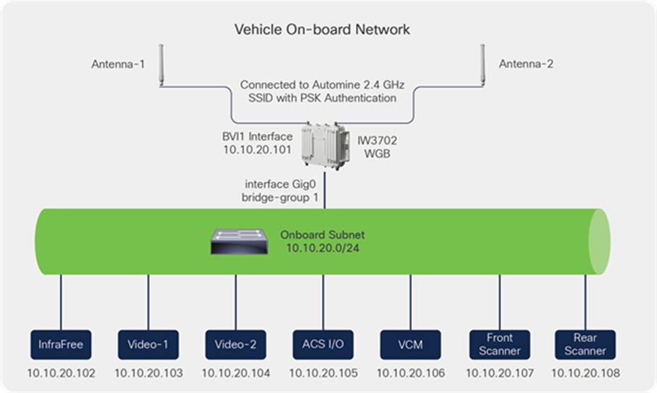
Equipment connectivity using a Cisco IW3702 workgroup bridge
A workgroup bridge (WGB) is an access point that is configured to act as a wireless client toward the wireless infrastructure, with the goal of providing Layer 2 connectivity for the devices connected to its Ethernet interface. For our underground mining autonomous vehicle use case, the WGB is installed on the vehicle to provide network connectivity to devices such as cameras, I/O devices, and Programmable Logic Controllers (PLCs) that are present on board the vehicle. These devices need connectivity back to the AutoMine® platform located in a centralized control room.
Note: Where more than one client Ethernet device exists behind the WGB, an Industrial Ethernet (IE) switch will be required. The various clients can then be connected to the IE switch, and the IE switch is then connected to the Ethernet port of the WGB. For the AutoMine® use case, there are multiple devices on the autonomous vehicle that need connectivity; hence there is a need for an IE switch on the vehicle.
Equipment network topology
The figure below shows the network topology of a single level, with both the network infrastructure and access barriers.
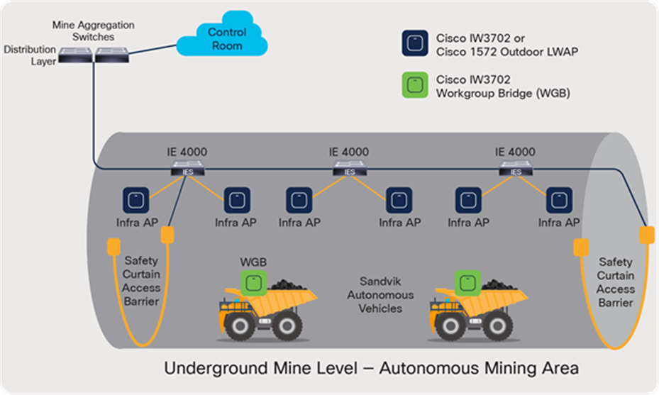
Example level within an underground mine
Visibility into and management of the mine network infrastructure can be achieved with any Simple Network Management Protocol (SNMP)-based network management application such as Cisco Prime® Infrastructure if already used.
The Cisco wireless LAN controller already offers a built-in web-based portal for monitoring and management of the wireless network.
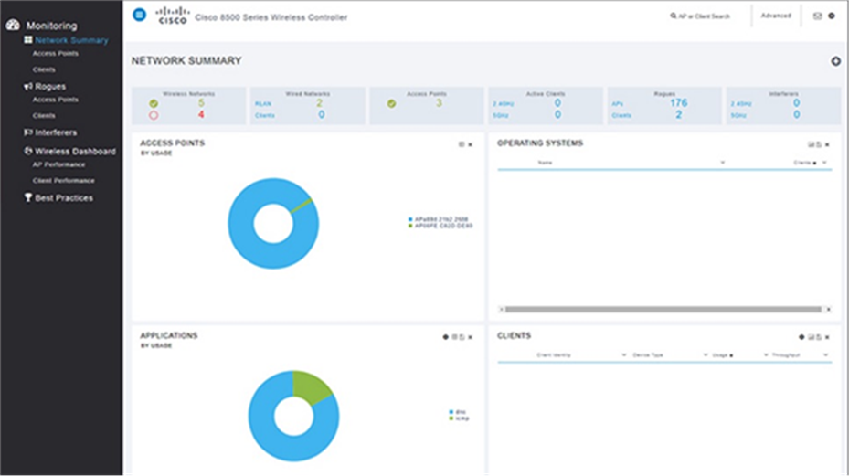
Cisco Prime Infrastructure wireless network management tool
Cisco Industrial Network Director
Cisco Industrial Network Director (IND) provides operations-centric network management for industrial Ethernet networks. The system supports industrial automation protocols such as Common Industrial Protocol (CIP), PROFINET, Open Platform Communications Unified Architecture (OPC-UA), MODBUS, Building Automation Control Network (BACnet), etc. to discover automation devices such as PLCs, I/O and HMI devices, and drives and delivers an integrated topology map of automation and networking assets to provide a common framework for operations and plant IT personnel to manage and maintain the industrial network.
The system uses the full capabilities of the Cisco Industrial Ethernet product portfolio to make the network accessible to non-IT operations personnel. The simple user experience streamlines network monitoring and delivers rapid troubleshooting of common network problems found in industrial environments.
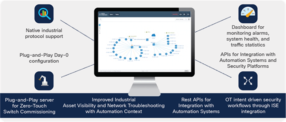
Cisco Industrial Network Director
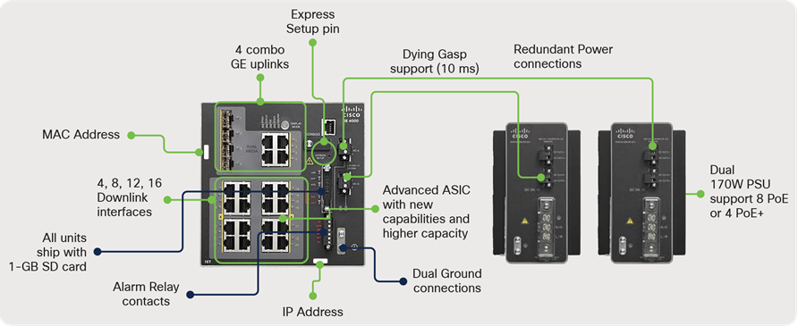
Cisco IE 4000 Series Switches
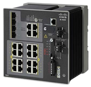
Cisco IE 4000 Series Switch
● Ruggedized: Complies with standards for utility and manufacturing deployments
● High Mean Time Between Failures (MTBF): No moving parts, dual DC inputs, and swap drive
● Scales with large Layer 2 and 3 forwarding tables
● Advanced IP routing features for aggregation deployments
● High performance: All packet forwarding in hardware
● Advanced Quality of Service (QoS) and security features performed in hardware for deterministic behavior (modular QoS command-line interface [MQC])
● Network Address Translation (NAT)
● DIN rail mount
● 4 Gigabit Ethernet combo (SFP and copper) uplinks in every model
● Power over Ethernet (PoE) and PoE+ ports (model dependent)
● SD card backup and external storage
● 2 dry-contact alarm inputs and 1 output alarm for temperature, power, and storage
IE 4000 Series data sheet: https://www.cisco.com/c/en/us/products/collateral/switches/industrial-ethernet-4000-series-switches/datasheet-c78-733058.html
Cisco IE 4000 Series power configuration options
AC-to-DC 54V DC power supply
● Part number: PWR-IE170W-PC-AC=
● Nominal AC input: 100 to 240V, 2.3A, and 50 to 60 Hz
● Supported AC input: 90 to 264V AC
● Nominal DC input: 125 to 250V DC
● Supported DC input: 106 to 300V DC
● Fixed output: 54V DC and 3.15A
● W x H x D: 3.4 x 5.8 x 5.2 in. (8.6 x 14.7 x 13.2 cm)
● Weight: 3.88 lb (1.76 kg)
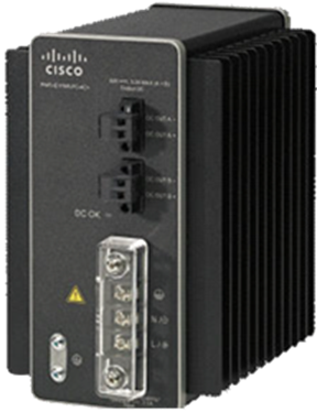
AC-to-DC 54V DC power supply
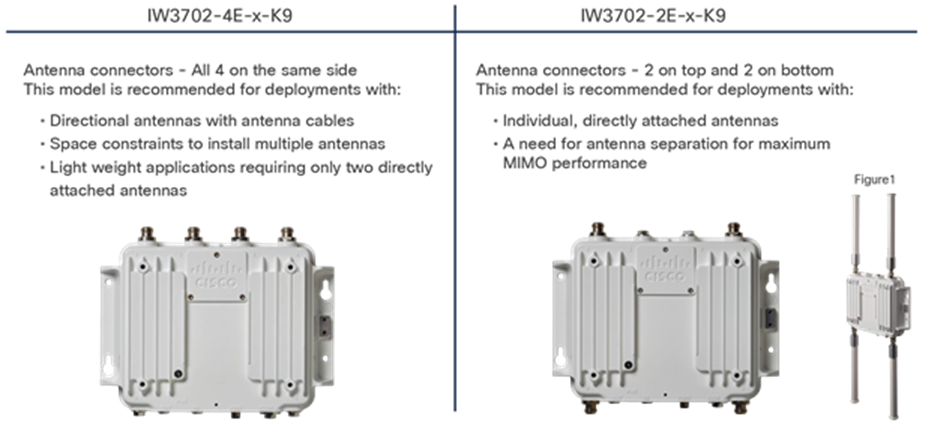
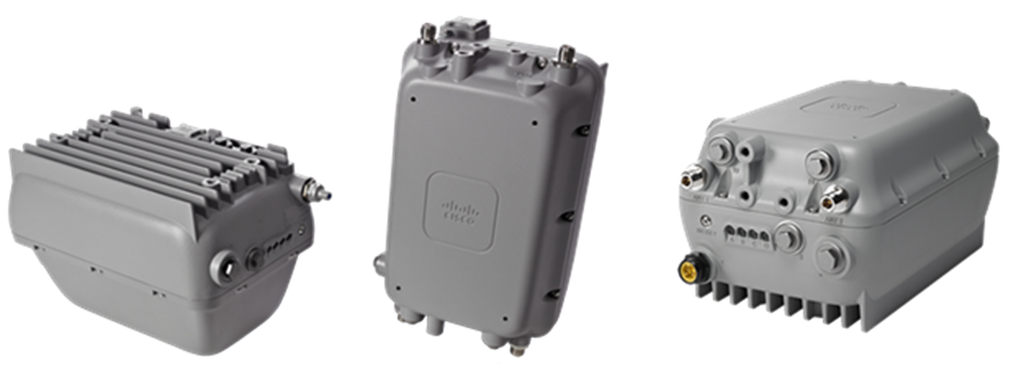
Cisco Industrial Wireless 3702 Access Point
Industrial wireless access point with speeds up to 1.3 Gbps with 802.11ac Wave 1 support.
● Extremely rugged IP67-rated housing to protect against liquid and dust ingress compliant with the EN 60529 standard
● Capable of operating in temperatures from -58° to 167°F (-50° to 75°C (-40°C [-40°F] for cold start)
● Vibration rated for transportation and mining applications
● M12 Ethernet and DC power connectors for vibration and shock resistance
● Versatile RF coverage with external N-type antenna connectors
● Range of 10V DC to 60V DC power input in addition to PoE/PoE+ to support a wide variety of power sources
IW3702 data sheet: https://www.cisco.com/c/en/us/products/collateral/wireless/industrial-wireless-3700-series/datasheet-c78-734968.html
Cisco IW3702 enclosure and connectors
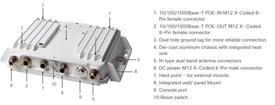
Cisco IW3702 enclosure and connectors (continued)
Cisco Aironet 1572 industrial access point
Important note: The Aironet 1572 AP is at end of sale as of November 2020. For new underground mining deployments, we recommend using IW3702 APs. However, if you currently have an existing underground wireless deployment consisting of Aironet 1572 APs, the solution has been validated to work with it.
Cisco Aironet 1572 access points
Cisco wireless LAN controllers
Cisco Wireless LAN Controllers (WLCs) provide centralized control, management, and troubleshooting for wireless deployments. The WLAN controller provides the lightweight AP its configuration and also functions as a switch for all the wireless traffic. It also consolidates management for the entire wireless network in one place. WLCs are physical devices that are rack mounted in the core data room and communicate with all APs at the same time. This allows for quick and easy configuration of multiple APs without having to manually configure each one.
A WLC also eliminates the need to rearchitect the wired network to host a WLAN. As you might assume, scalability is greatly improved by the addition of a WLC, as it easily allows the installation of more APs onto the network and reduces deployment and management complexity.
We recommend deploying a pair of Cisco 3504 WLCs for small to medium-sized deployments (up to 150 APs and 3000 clients), and a pair of Cisco 5520 WLCs for larger deployments (up to 1500 APs and 20,000 clients).
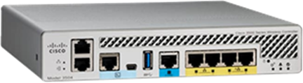
Cisco 3504 Wireless Controller
3504 WLC data sheet: https://www.cisco.com/c/en/us/products/collateral/wireless/3504-wireless-controller/datasheet-c78-738484.html

Cisco 5520 Wireless Controller
5520 WLC data sheet: https://www.cisco.com/c/en/us/products/collateral/wireless/5520-wireless-controller/datasheet-c78-734257.html
Cisco Catalyst 9300 Series access layer switches
The Cisco Catalyst 9300 Series Switches are the next generation of enterprise-class, stackable, aggregation layer switches. They provide full convergence between wired and wireless networks on a single platform.
● Delivers 480 Gbps stacking bandwidth capacity
● Flexible uplinks: Cisco Multigigabit, 1 Gbps, 10 Gbps, 25 Gbps, and 40 Gbps. Fixed (9300L) and modular (9300) options
● Flexible downlinks: Cisco Multigigabit, 5 Gbps, 2.5 Gbps, or 1 Gbps copper, or 1 Gbps fiber. Perpetual Cisco UPOE®+, Cisco UPOE, and PoE+ options
● Supports Encrypted Traffic Analytics (ETA), Audio Video Bridging (AVB), Cisco Umbrella® cloud security, MACsec-256 encryption, hot patching, Nonstop Forwarding/Stateful Switchover (NFS/SSO), and redundant power and fans
Note: The embedded WLC within the Catalyst 9300 Series has not been validated and is not supported as part of the solution.
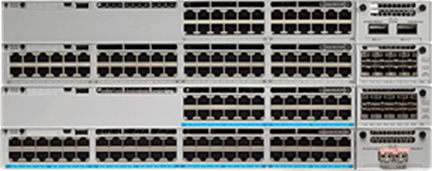
Cisco Catalyst 9300 Series Switch
Catalyst 9300 Series data sheet and switch model selector: https://www.cisco.com/c/en/us/products/collateral/switches/catalyst-9300-series-switches/nb-06-cat9300-ser-data-sheet-cte-en.html
Cisco Catalyst 9500 Series distribution/core layer switches
The Cisco Catalyst 9500 Series Switches are the next generation of enterprise-class, stackable, core layer switches.
● 4-core x86, 2.4-GHz CPU, 16-GB DDR4 memory, and 16 GB of internal storage
● Up to 6.4-Tbps switching capacity with up to 2 Bpps of forwarding performance
● Up to 32 nonblocking 100 Gigabit Ethernet QSFP28 ports
● Up to 32 nonblocking 40 Gigabit Ethernet QSFP+ ports
● Up to 48 nonblocking 25 Gigabit Ethernet SFP28 ports
● Up to 48 nonblocking 10 Gigabit Ethernet SFP+ ports
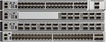
Cisco Catalyst 9500 Series Switch
Catalyst 9500 Series data sheet and switch model selector: https://www.cisco.com/c/en/us/products/collateral/switches/catalyst-9500-series-switches/nb-06-cat9500-ser-data-sheet-cte-en.html
Cisco Firepower Next Generation Firewalls (Cisco Secure Firewalls)
Firewalls can be placed between the customer’s enterprise network and the AutoMine® network to help ensure the integrity of the AutoMine® system. Firewalls are not recommended within the AutoMine® network itself due to sessions timeouts.
The recommendation is to use a Layer 3 switch or router within the AutoMine® network. If OptiMine® is used, we recommend having a firewall between the mine network and the enterprise network to control access to the required interfaces.
Cisco provides validated designs that are applicable to designing industrial networks, including the use of an industrial DMZ, including firewall placement and security architectures. These designs are based on the principles in IEC62443.
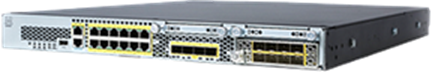
Cisco Firepower® 2100 Series appliance
AutoMine® network configuration requirements
● The IP address prefix range used is normally provided by the customer. RFC 1918 or customer-defined prefixes can be used.
● Subnet sizes depend upon the size of the mine network.
● Static IP addresses are currently used for the fixed infrastructure (switches) or the equipment (Moxa client).
● Access points are configured and managed by the WLC (Cisco access points operate in lightweight mode).
● A single /24 IP address subnet can accommodate a moderate-sized operating area.
One SSID needs to be created and reserved for AutoMine®. Only AutoMine® components should be allowed to connect to this SSID. This SSID is mapped to a single VLAN for AutoMine.
Authentication and authorization
AutoMine® does not require authentication and authorization to operate.
TACACS+ is recommended for user access to all equipment (integrated with the corporate Active Directory if possible).
End device authentication onto the network is recommended using MAC Authentication Bypass (MAB) due to 802.1X not being supported in industrial-type devices (for example, access barriers). Use a RADIUS server for authentication.
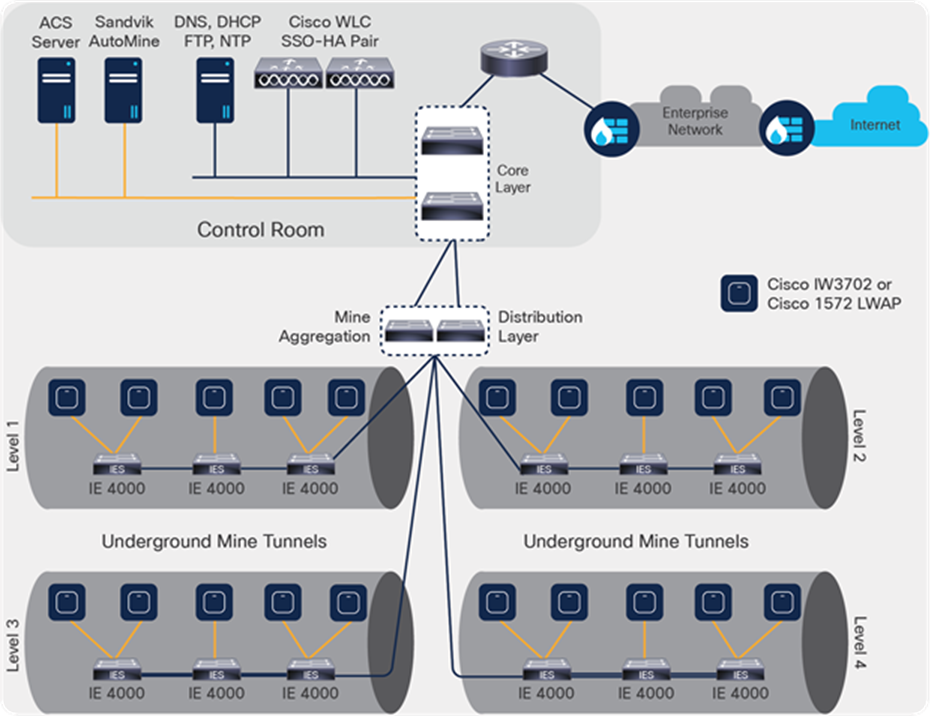
The Sandvik AutoMine® logical network comprises three areas:
● Control room, which houses the following components:
◦ AutoMine® operator stations
◦ ACS safety system and PLC
◦ Cisco WLC SSO-HA pair
◦ Infrastructure services: DNS, DHCP, NTP, FTP
◦ Core layer switches
◦ Mine aggregation distribution layer switches
● Underground mine area:
◦ Cisco IE 4000 Series ruggedized switches
◦ Cisco IW3702 infrastructure APs
◦ Sandvik ACS safety curtains
● Autonomous vehicle setup:
◦ Cisco WGB client
◦ Ruggedized switch
◦ Sandvik AutoMine® components
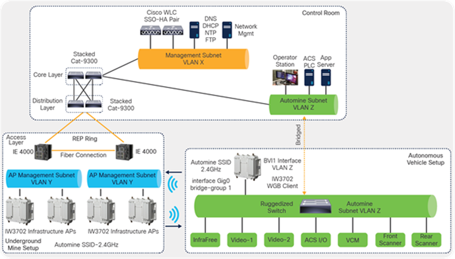
Sandvik AutoMine® logical network design
A wireless site survey of the mine area is crucial to the successful deployment of an underground mine network. A wireless site survey aids with placing the APs, addressing any coverage gaps, tuning the power settings, tuning the RF settings of the individual APs, channel planning, and spectrum analysis. A post-installation RF site survey is also highly recommended to tune the settings appropriately so as to provide the desired coverage.
It is also important to conduct a site survey at regularly scheduled intervals or whenever the topography of the mine changes (new levels or tunnels added, etc.).
Sandvik is capable of providing wireless survey and drive tests as part of the project delivery.
The “AutoMine SSID” WLAN uses the 2.4 GHz spectrum and should be designed to use Wi-Fi channels 1, 6, and 11, which are the only nonoverlapping channels available in that range. The network should be designed so that adjacent access points are on different channels to avoid any kind of interference.
Wireless coverage
● Coverage of the access point network must be according to Sandvik´s requirements.
● Coverage areas must overlap and signal quality must be good in every location where the AutoMine system is used.
● Minimum required signal strength is -55 dBm in all areas. In areas where handovers occur, both access points should be above the minimum required signal strength.
● No other systems should be using the 2.4 GHz ISM spectrum in the area where AutoMine is to be deployed.
● The main goal when designing the wireless coverage for the AutoMine® application is to provide adequate signal strength for wireless clients throughout the mine network and to be able to support the required data rate (10 Mbps per loader).
In addition, wireless cell size should be controlled to achieve the desired number of clients per AP, and to minimize co-channel interference between cells:
● Determine the maximum number of wireless clients (loaders, etc.), including future expansion required.
● Identify redundancy requirements for coverage, such as if two (or more) APs should be seen from any point to provide for failures.
● Perform a professional site survey to determine the number and locations of the APs that can cover the area with the required level of redundancy. The site survey should also determine the appropriate antenna types and verify link performance and supported data rates. For details on how to perform an effective wireless site survey, please refer to Chapter 4, Wireless Site Survey, of the Cisco Validated Design (see “Useful References” below).
● Design the wireless coverage to maintain the parameters listed in the table below.
Table 3. RF network parameters
| Parameter |
Recommended value |
| Received Signal Strength Indicator (RSSI) |
Minimum 55 dBm |
| Signal-to-Noise Ratio (SNR) |
Minimum 25 dB |
| Supported minimum data rate |
10 Mbps per machine |
● Configure transmit power manually for each device to provide adequate coverage.
● Change the transmit power from the maximum to reduce signal propagation outside the intended area and to minimize Co-Channel Interference (CCI) onsite.
● Use static channel allocation in the WLAN. Determine whether wireless channels have to be reused based on the spectrum availability. A channel allocation scheme should provide maximum distance separation between cells using the same channels.
● Do not reuse the channels for wireless cells operating with high utilization and high client count, unless complete signal separation can be achieved.
● If a channel is reused and CCI is expected, the available bandwidth is essentially shared between the wireless cells. The total packet rate should be calculated, including every application using the channel.
For detailed design and implementation guidance for deployment of an underground mine wireless network to support Sandvik AutoMine® and OptiMine®, refer to the Wireless Networks Enabling Autonomous Vehicles for Underground Mines Cisco Validated Design (CVD) document located at: https://www.cisco.com/c/en/us/td/docs/solutions/Verticals/Industrial_Automation/IA_Verticals/Mining/Mining1_5/IA-Mining-DG/IA-Mining-DG.html
Appendix A: Physical installation
Physical installation of Cisco Industrial Ethernet switches
The IE 4000 Series is installed into the Sandvik IP67 AutoMine® network cabinet (part number BG01102390), which is precabled for the IE 4000 Series, DC power supply, and entry/exit for both fiber cables, fixed Ethernet-based devices (such as laser gates), and M12 copper cables to the IW3702 AP.
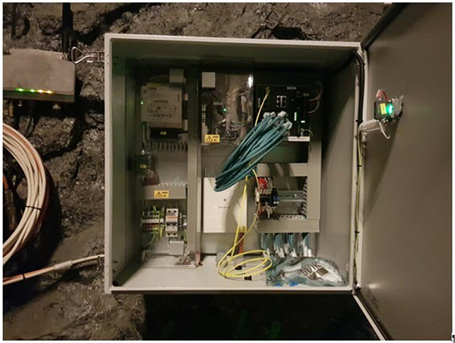
Prefabricated mine enclosure for Cisco IE switch and associated components
About Cisco
Cisco is the worldwide leader in networking that transforms how people connect, communicate, and collaborate. Information about Cisco can be found at https://www.cisco.com.
About Sandvik Mining and Rock Solutions
Sandvik Mining and Rock Solutions is a global leading supplier of equipment and tools, parts, services and technical solutions for the mining and construction industries. It’s a world leader in mining automation, implementing digital mining solutions for more than two decades.
Headquarters
Box 510, SE-101 30
Stockholm, Sweden