Cisco ACI SR/MPLS Handoff Architecture White Paper
Available Languages
Bias-Free Language
The documentation set for this product strives to use bias-free language. For the purposes of this documentation set, bias-free is defined as language that does not imply discrimination based on age, disability, gender, racial identity, ethnic identity, sexual orientation, socioeconomic status, and intersectionality. Exceptions may be present in the documentation due to language that is hardcoded in the user interfaces of the product software, language used based on RFP documentation, or language that is used by a referenced third-party product. Learn more about how Cisco is using Inclusive Language.
Telecom Service Providers (SPs) are using Cisco Application Centric Infrastructure (Cisco ACI®) to build distributed 5G-ready telecom data centers. Cisco ACI provides consistent policy, automation, telemetry, intelligent service chaining, and ease of operations to geographically distributed central, regional, and edge telecom data centers. While customers are taking advantage of Cisco ACI in the data center space, they are also looking to expand the automation and consistent policy across data-center and transport domains. SP customers are using Segment Routing (SR) or Multi-Protocol Label Switching (MPLS) in the transport domain; therefore, there is a requirement to do SR/MPLS-based handoff from data centers.
To provide a solution to these requirements, starting from Cisco ACI Release 5.0(1), SR/MPLS handoff is supported in ACI. The SR/MPLS handoff solution is supported for all elements of distributed data center solution of Cisco ACI, namely Cisco ACI Multi-Site, Multi-Pod, and remote leaf. SR/MPLS handoff from data centers allows SP customers to use consistent policy, automation, and scalability and better monitoring capabilities across data centers and transport.
This section highlights the key use-cases of SR/MPLS handoff from Cisco ACI.
Unified SR/MPLS transport
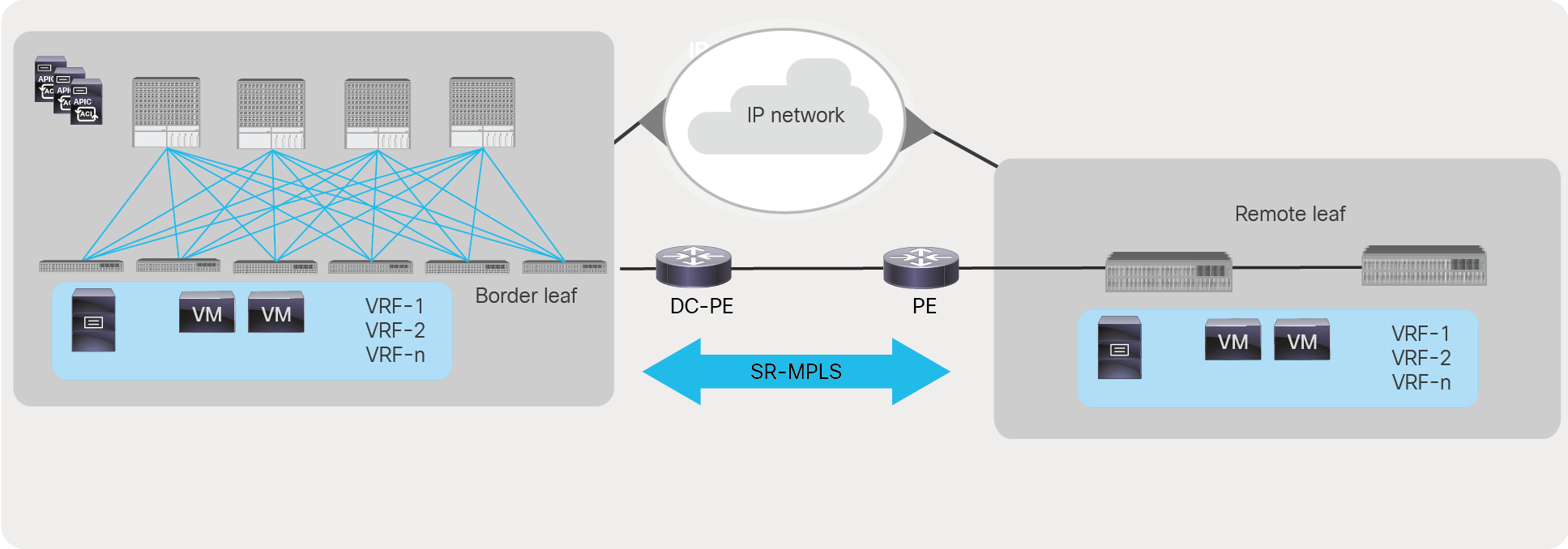
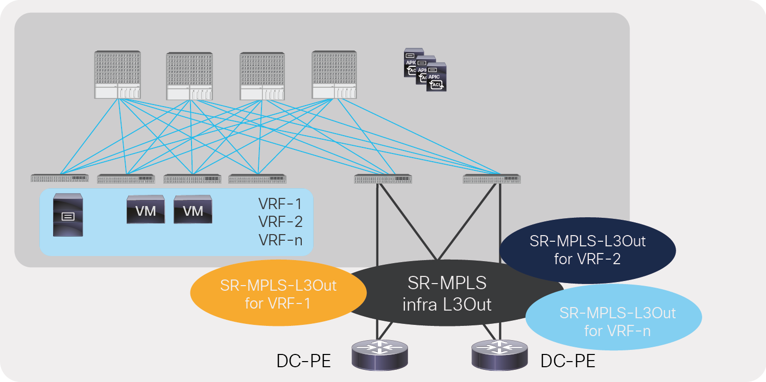
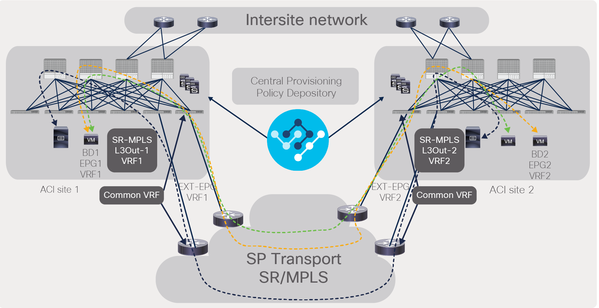
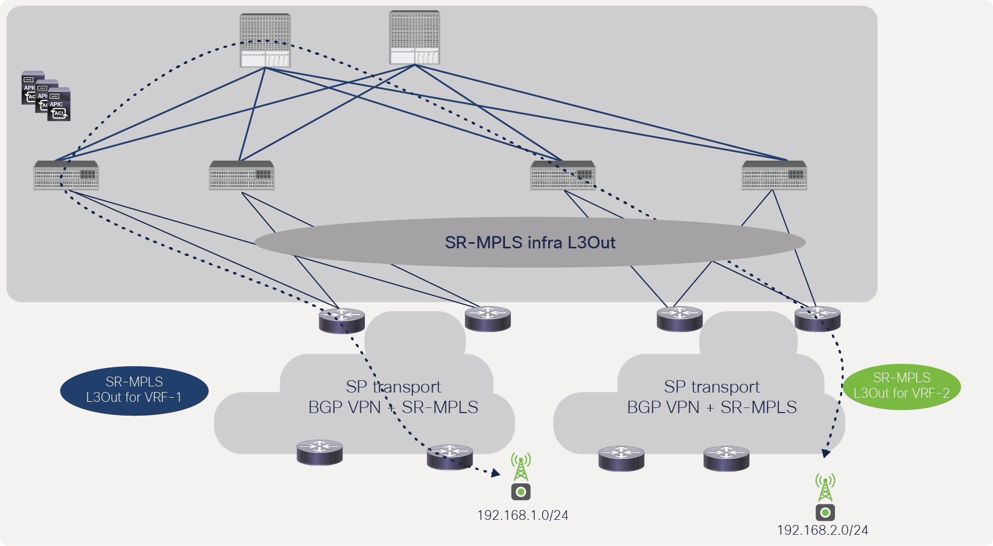
Service-provider customers use SR/MPLS encapsulation in the transport networks. Data center to transport handoff with SR/MPLS allows SP customers to use a single SR/MPLS data-plane protocol on their transport devices. Cisco ACI uses VXLAN within the fabric to solve data center challenges such as workload mobility and integration with different types of virtual environment to support automation and visibility. Traditionally, the handoff from the ACI fabric can be done either by native IP or by using VXLAN. In either handoff case, transport devices either must support VXLAN or manually configure IP handoff. By allowing handoff from SR/MPLS, SP customers don’t have to worry about supporting VXLAN or manually configuring IP handoff. Figure 1 shows SR/MPLS handoff across Cisco ACI Multi-Site, Multi-Pod, and remote leaf.
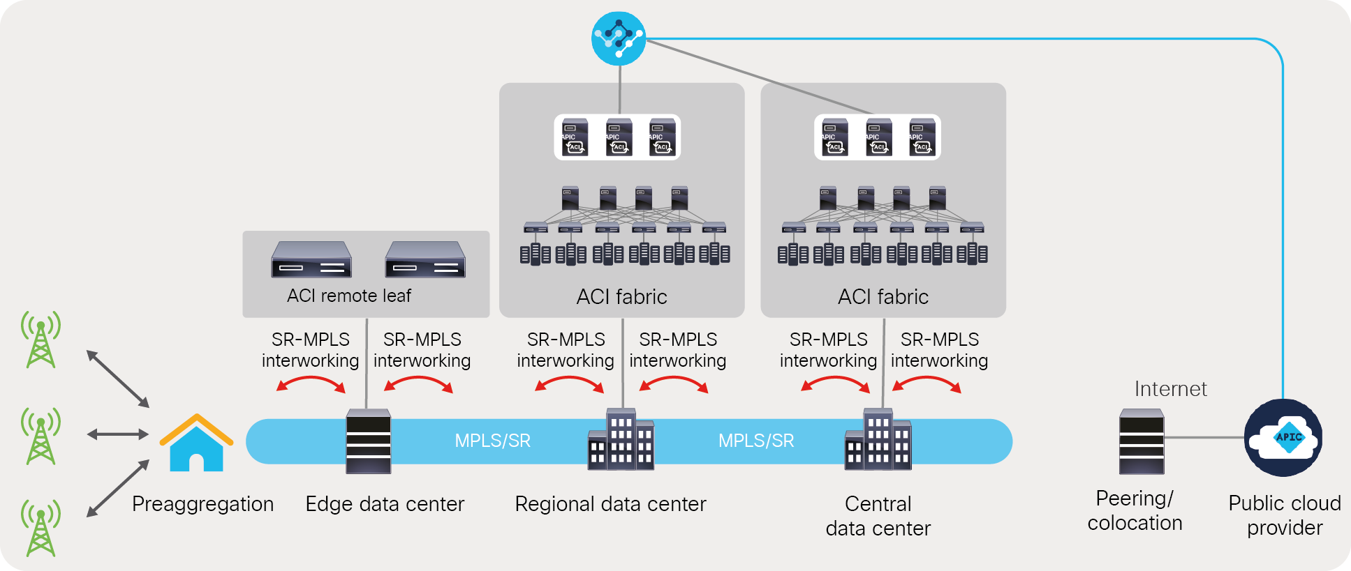
Unified SR/MPLS-based transport across distributed data centers built with Cisco ACI Multi-Site, Multi-Pod, and remote leaf
Automated and scalable data-center handoff
IP handoff from ACI (Figure 2) requires a separate interface and routing protocol for each VRF to provide connectivity from the data center to the transport or external device. This type of connectivity is called a VRF-lite connection. In an SP or large enterprise environment, many VRFs may be deployed. In these scaled VRF environments, separate sub-interfaces and routing protocols for each VRF causes automation and scale issues.
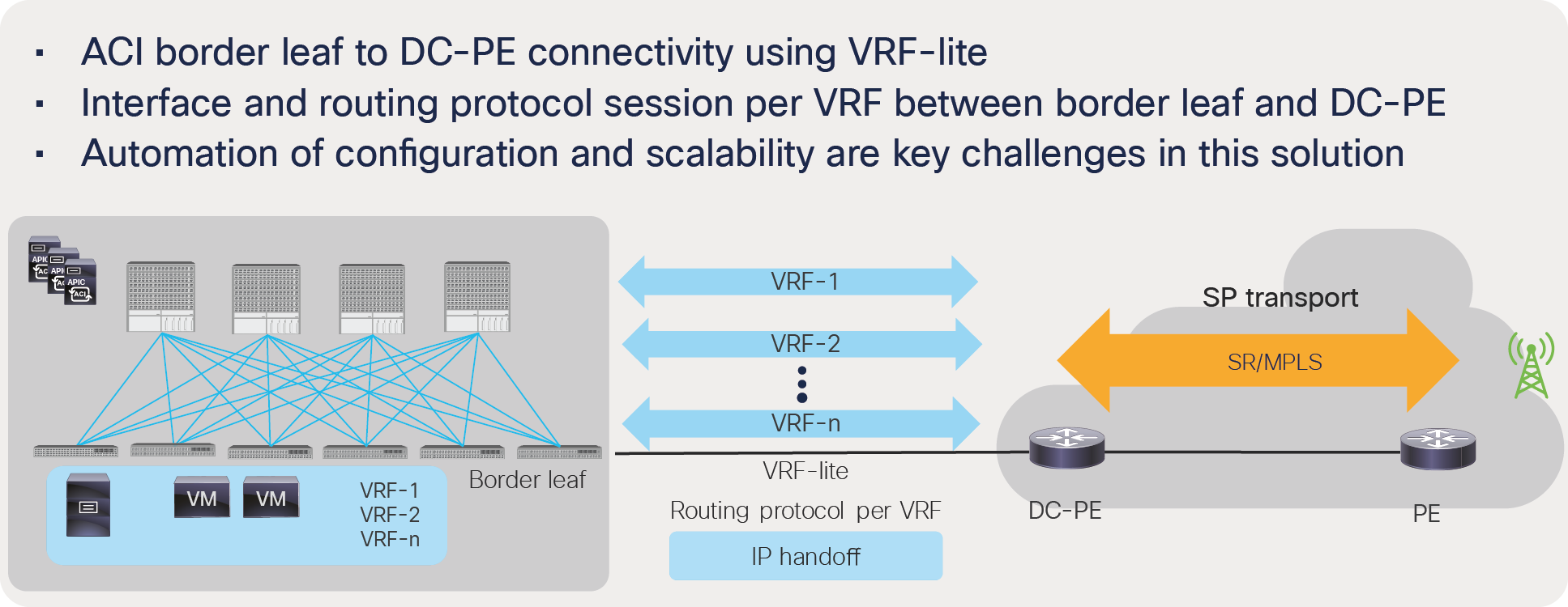
IP handoff from ACI
With the SR/MPLS handoff from ACI, a single BGP EVPN session can exchange the information of all the prefixes in all the VRFs instead of from each routing protocol session and sub-interface per VRF (Figure 3). This results in better scale and automation for both transport and the data center.
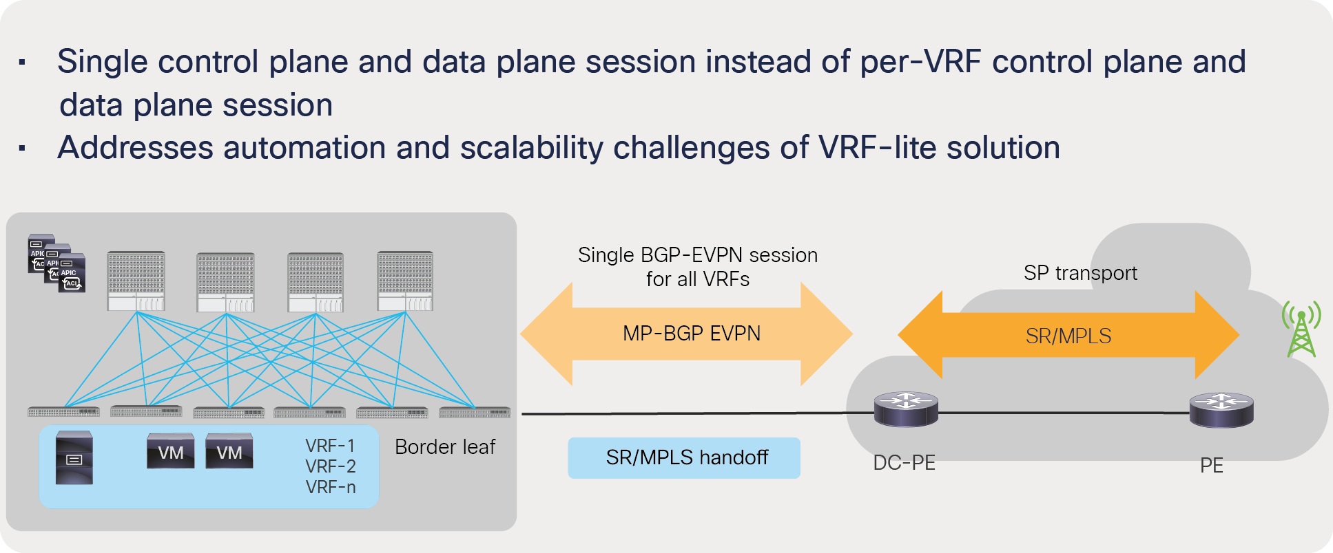
SR/MPLS handoff from ACI
Consistent policy across the data center and transport
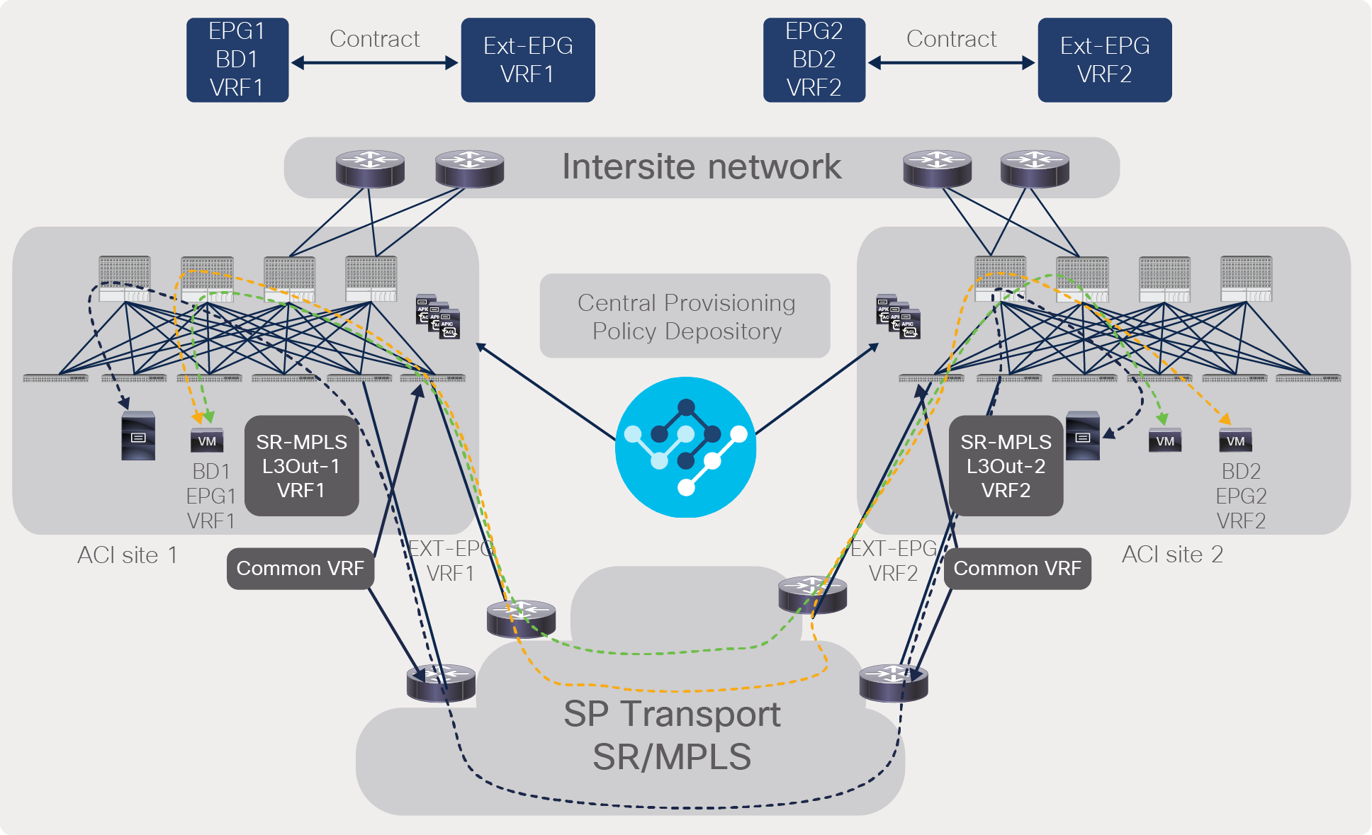
The customer can advertise the Border Gateway Protocol (BGP) color community for prefixes from Cisco ACI border leafs and use this community on the Provider Edge (PE) routers to define an SR policy in transport. This automated mapping between the data center and transport provides better automation and policy consistency across data-center and transport domains. Figure 4 shows how to achieve this.
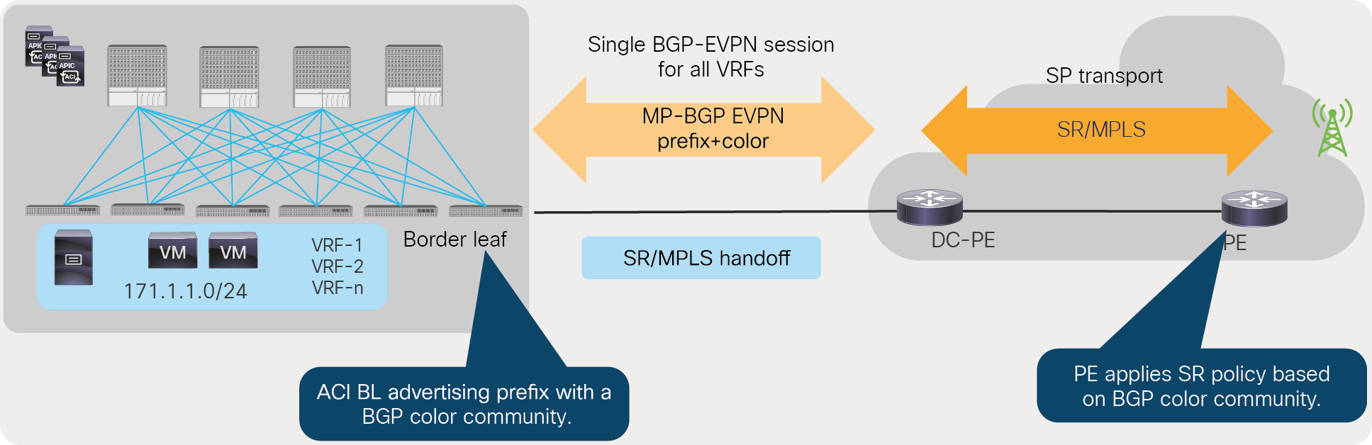
Consistent policy across the data center and SP transport using BGP color community
Another option for customers to achieve consistent policy across the data center and transport is by marking packets with DSCP or EXP values from the data center and using these values during transport to define SR policies. Figure 5 shows how to achieve this.
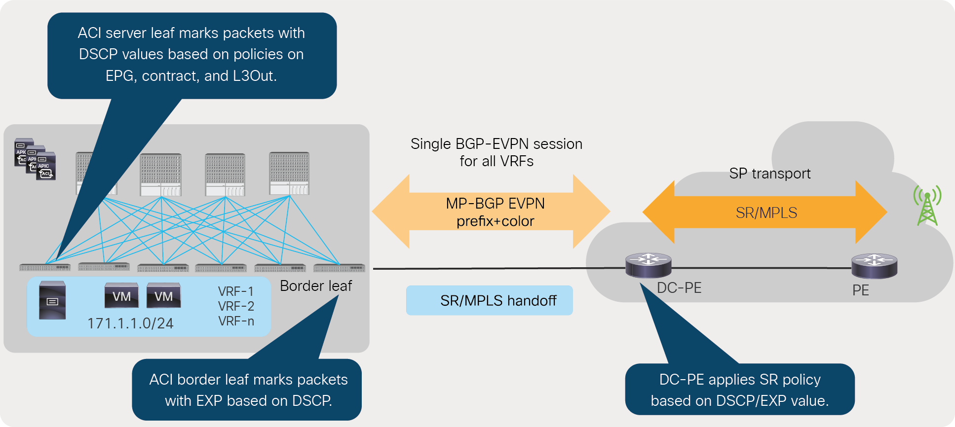
Consistent policy across the data center and SP transport using DSCP/EXP values set in the data center
Lastly, if transport doesn’t support BGP color community or SR policies based on DSCP/EXP values, customers can define prefix-based SR policies based on prefixes advertised by the ACI fabric using BGP EVPN session between a border leaf and a Data Center Provider Edge (DC-PE).
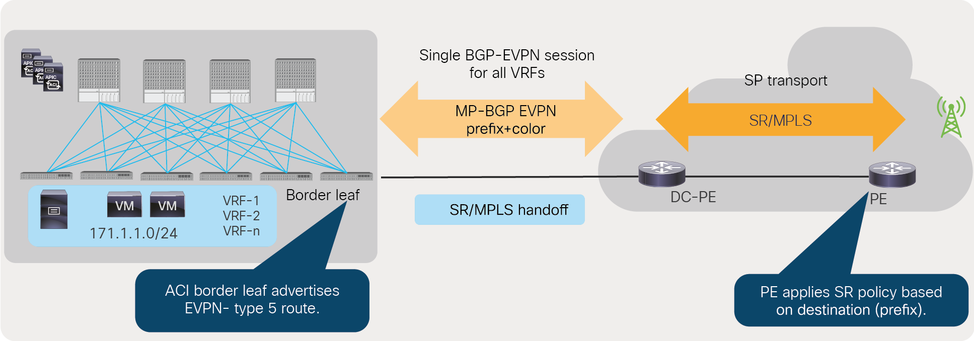
SR policy in SP transport using destination prefix
Data center to data center traffic flow monitoring in a transport network using existing monitoring tools
Traditionally, existing monitoring tools in a transport network can monitor IP/SR/MPLS packets, but these monitoring systems typically can’t monitor VXLAN encapsulated packets. By default, data center to data center traffic flow is encapsulated with a VXLAN header, but with the Cisco ACI to SR/MPLS handoff solution, data center to data center traffic flows are encapsulated in the SR/MPLS header. This allows service-provider customers to use existing monitoring tools to monitor data center to data center traffic.
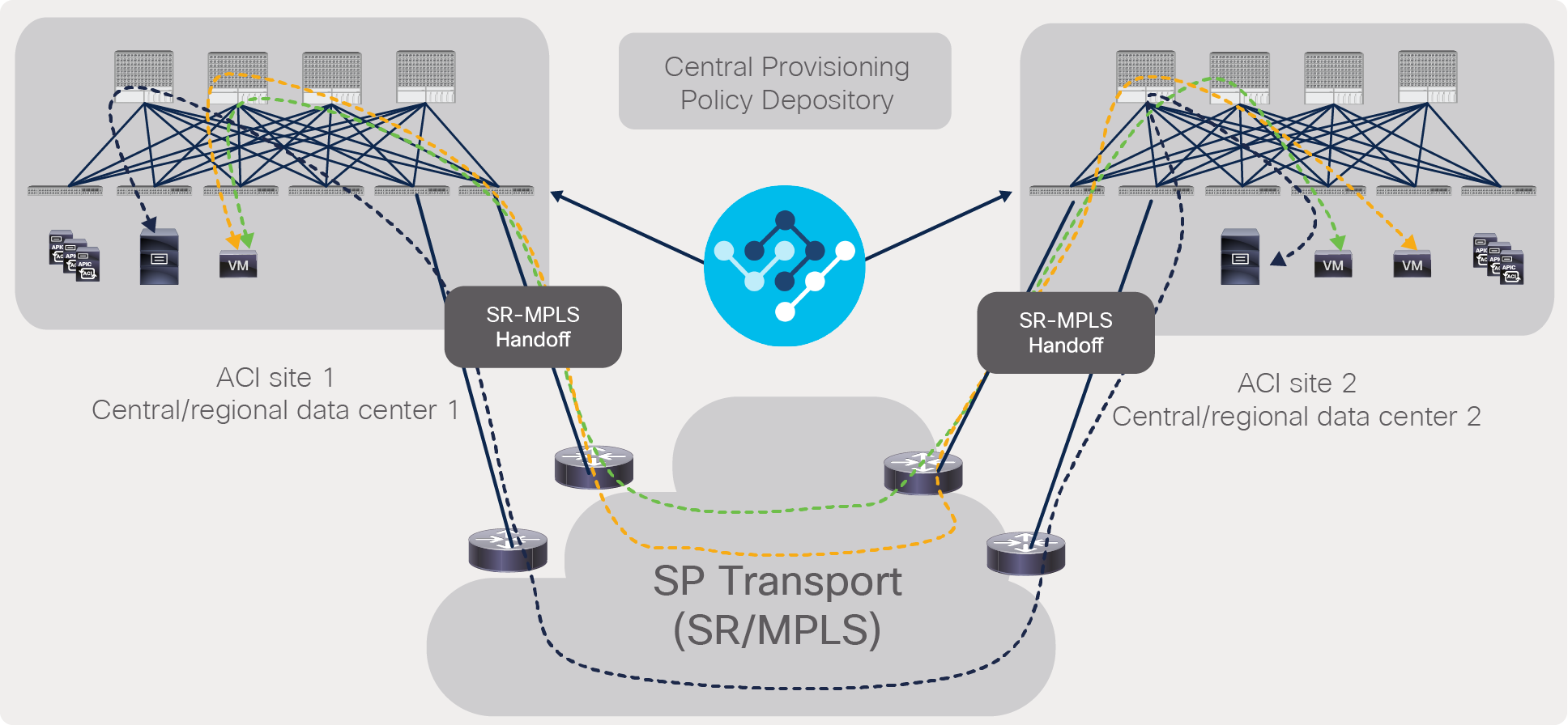
Figure 7 shows that the traffic flow between the ACI main data center and the ACI remote leaf is using an SR/MPLS header. The same would apply for traffic flow between ACI pods and sites.
Data center to data center traffic flow monitoring with SR/MPLS handoff
Cisco ACI to SR/MPLS handoff solution overview
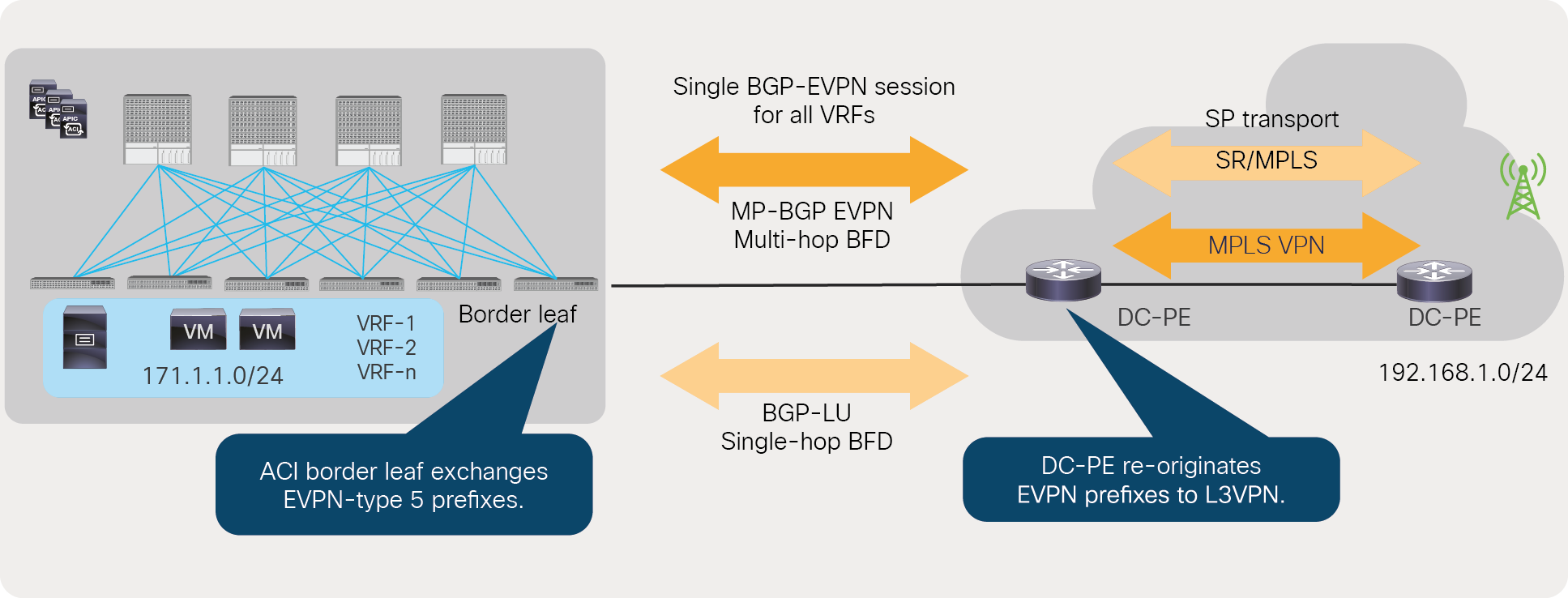
The Cisco ACI to SR/MPLS handoff solution uses BGP EVPN between the DC-PE and ACI border leaf to exchange VPN prefix information between the ACI border leaf and DC-PE. The BGP EVPN session also exchanges MPLS labels for each VRF to DC-PE to uniquely identify each VRF. The DC-PE re-originates the EVPN prefixes in L3VPN to provide end-to-end reachability in the SP core.
To provide reachability between the DC-PE and the ACI border leaf, a BGP-Labeled Unicast (BGP-LU) session is used on the ACI border leaf and its neighboring router. Using a BGP-LU session, the ACI border leaf exchanges the reachability of loopbacks and Segment ID (SID) index with its neighboring router. Customers can use a single-hop Bidirectional Forwarding Detection (BFD) for the BGP-LU session and a multi-hop BFD for BGP EVPN sessions for faster convergence.
Cisco ACI to SR/MPLS handoff solution overview
In terms of configuration, the Cisco ACI SR/MPLS handoff solution uses SR-MPLS-infra L3Out to configure BGP-LU, BGP EVPN, and BFD. Users can then select the VRF that needs to be externally connected using SR-MPLS-VRF L3Out. Users can also configure route-maps to selectively import/export the prefixes into and out from the ACI fabric.
The Cisco ACI to SR/MPLS handoff solution is supported starting from Cisco ACI Release 5.0(1) release with following hardware.
● Leaf models: Cisco Nexus 9000 series switches with names that end in FX, and later (for example, N9K-C93180YC-FX) are supported.
● Fixed spine models: Cisco Nexus 9332C Switch, Cisco Nexus 9364 Switch, and models with a -GX suffix (for example, Nexus 9316D-GX) are supported.
● Modular Spine models: Cisco Nexus 9500 modular switches equipped with line cards with name that end in EX, and later (for example N9K-X9732C-EX) are supported.
The Cisco ACI to SR/MPLS solution has been validated with these WAN Edge Routers: Cisco Network Convergence System 540 Series Routers, Cisco Network Convergence System 560 Series Routers, and Cisco 9000 Series Aggregation Services Routers. If you choose these WAN Edge Routers you should use Cisco IOS® XR Release 7.0.1 or later.
The Cisco ACI to SR/MPLS handoff solution uses standards-based implementation with SR/MPLS, BGP-LU, BGP EVPN, and prefix re-origination between BGP EVPN and VPNv4/v6. Any DC-PE that supports these technologies should be able to support Cisco ACI to SR/MPLS handoff. The above list outlines only the DC-PE devices that have been validated by Cisco in its internal labs.
Control and data plane for SR/MPLS handoff
This section will go into the details of implementing both control plane and data plane for SR/MPLS handoff. For the control plane, the Cisco ACI SR/MPLS handoff solution uses BGP EVPN and BGP-LU with BFD; for the data plane, it uses SR/MPLS labels advertised by BGP EVPN and BGP-LU. Before we go into the details regarding the control and data planes, let’s understand the multiple loopback addresses required on the ACI border leaf for the SR/MPLS handoff.
Loopback address on ACI border leaf
A Cisco ACI border leaf is configured with three loopbacks for the Cisco ACI to SR/MPLS handoff solution.
Router ID: A BGP session on a Cisco ACI border leaf requires a unique router ID. If the ACI border leaf is already configured with a router ID, then the ACI User-Interface (UI) provides a warning to explain to the user that the router-ID field should be left empty to allow SR/MPLS handoff to use the existing router ID. Changing the router ID will flap the existing BGP sessions, which will cause a traffic outage.
BGP EVPN loopback: This loopback is only used for control purposes. BGP EVPN loopback is configured on the ACI border leaf to build a BGP EVPN session with the DC-PE.
MPLS transport loopback: MPLS transport loopback is used for data-plane purposes. The BGP prefixes exchanged between the ACI border leaf and the DC-PE have the next hop as the MPLS transport loopback.
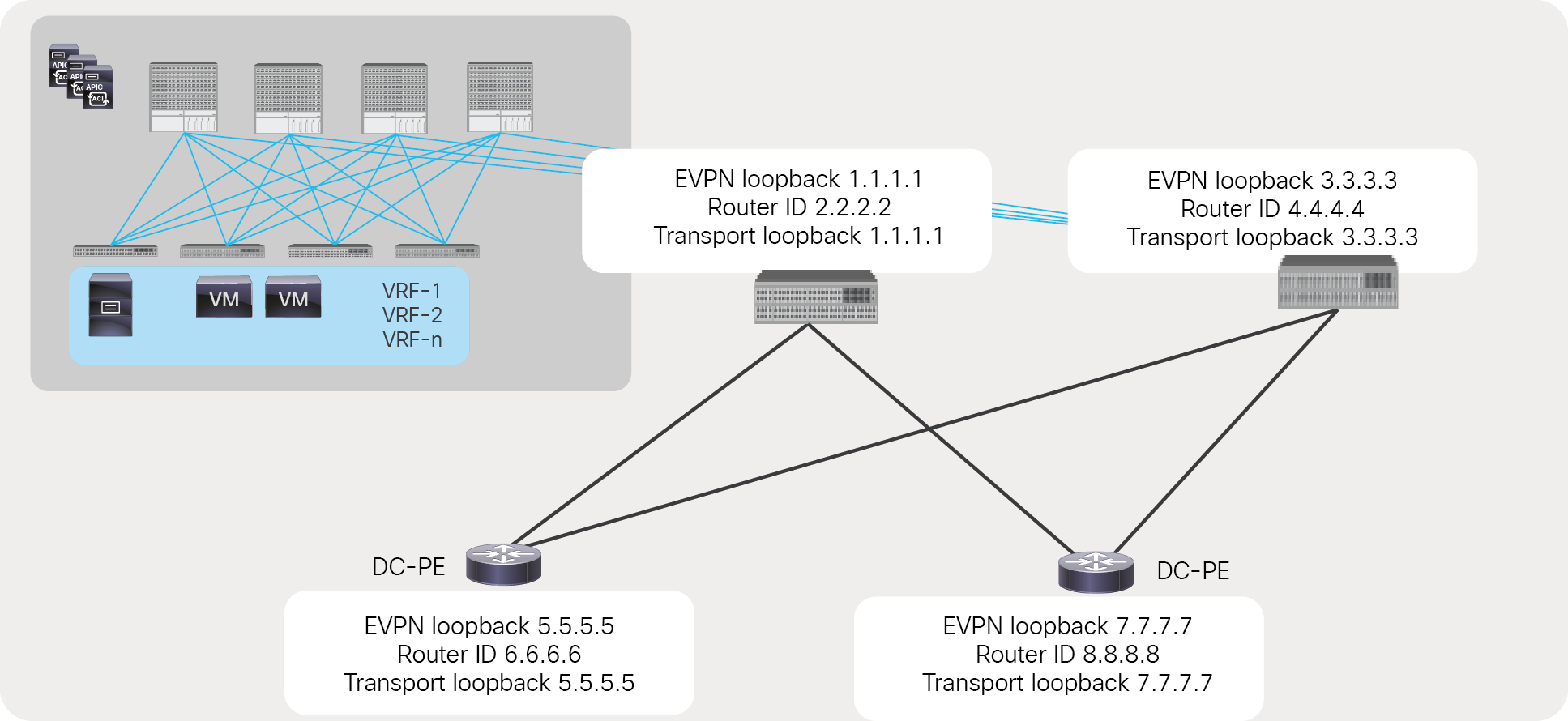
Loopbacks for the Cisco ACI to SR/MPLS handoff solution
BGP EVPN session
The ACI border leaf and the DC-PE use a BGP EVPN session to exchange VPN prefixes, VPN labels, and BGP communities, such as the color community. In this document, a BGP EVPN session between the ACI border leaf and DC-PE is also referred as overlay connectivity. Using BGP EVPN, an MPLS label is exchanged for each VRF between the DC-PE and ACI border leaf. In Cisco ACI Release 5.0(1), ACI supports eBGP neighborship only; therefore, the TTL value for a BGP EVPN session should be minimum of 2.
Multi-hop BFD
Multi-hop BFD on an ACI border leaf helps to detect the failure of a BGP EVPN session faster without depending on BGP timers. It is highly recommended to use BFD for failure detection since doing so helps to provide faster convergence. For multi-hop BFD, Cisco ACI supports a minimum timer of 250msec and a minimum-detect multiplier of 3.
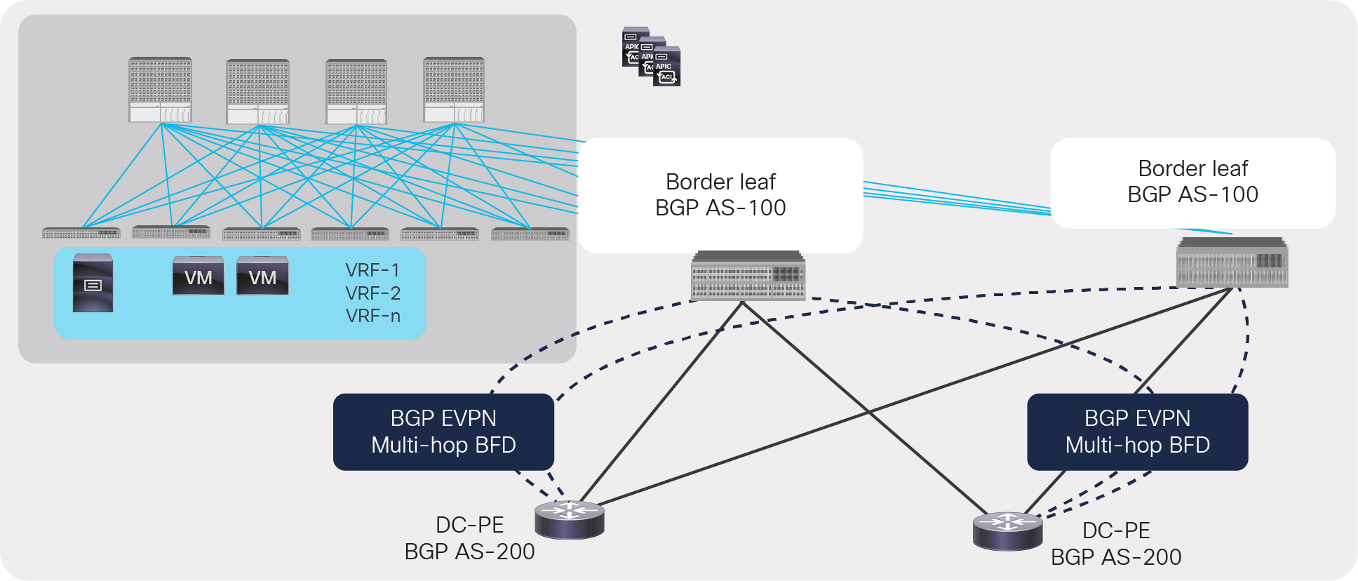
BGP EVPN session between ACI border leaf and DC-PE with multi-hop BFD
BGP-labeled unicast session
An ACI border leaf uses BGP-Labeled Unicast (BGP-LU) address-family neighbor with its next-hop router to exchange transport loopbacks prefix and label information. In this document, BGP-LU connectivity is also referred as underlay connectivity between the ACI border leaf and the DC-PE. BGP-LU session is enabled on all interfaces of ACI border leafs that are configured with SR/MPLS. Please note that ACI always advertises an implicit-null label for its transport loopback; therefore, incoming packets on ACI border leafs from the SR/MPLS network will only have a single label for the VRF. BGP-LU sessions in Cisco ACI Release 5.0(1) are supported with eBGP only.
Using BGP-LU session, an ACI border leaf also advertises a Segment ID (SID) index to its next-hop router. The segment ID index, along with Segment-Routing Global Block (SR-GB), is used in the SR domain between the ACI border leaf and the DC-PE to calculate the label for the transport loopback of the ACI border leaf and DC-PE. Calculating labels is explained in detail in the section “SR network between ACI border leaf and DC-PE.”
If the network between an ACI border leaf and a DC-PE is using MPLS and not SR, then the ACI border leaf can select BGP-LU connectivity as “MPLS” instead of “SR-MPLS,” and BGP-LU will not advertise the segment ID. This is explained in detail in the section “MPLS network between ACI borer leaf and DC-PE.”
BGP IPv4 address-family session
An ACI border leaf uses a BGP IPv4 address-family session to exchange a BGP EVPN loopback with its next-hop router. Since a BGP EVPN loopback is used for the control plane, no MPLS label is required for its connectivity; therefore, it’s not advertised using a BGP-LU session.
Single-hop Bidirectional Forwarding Detection (BFD)
An ACI border leaf uses single-hop Bidirectional Forwarding Detection (BFD) with its next-hop router for a BGP-LU and IPv4 address-family. A single-hop BFD with the next-hop router is useful to detect a “soft” failure, in which a physical link remains up, but the reachability to the next hop is down due to some forwarding problems. Cisco ACI supports a minimum BFD timer of 50msec and a minimum detect multiplier of 3 for a single-hop BFD. It is highly recommended to use BFD for fast failure detection to provide faster convergence.
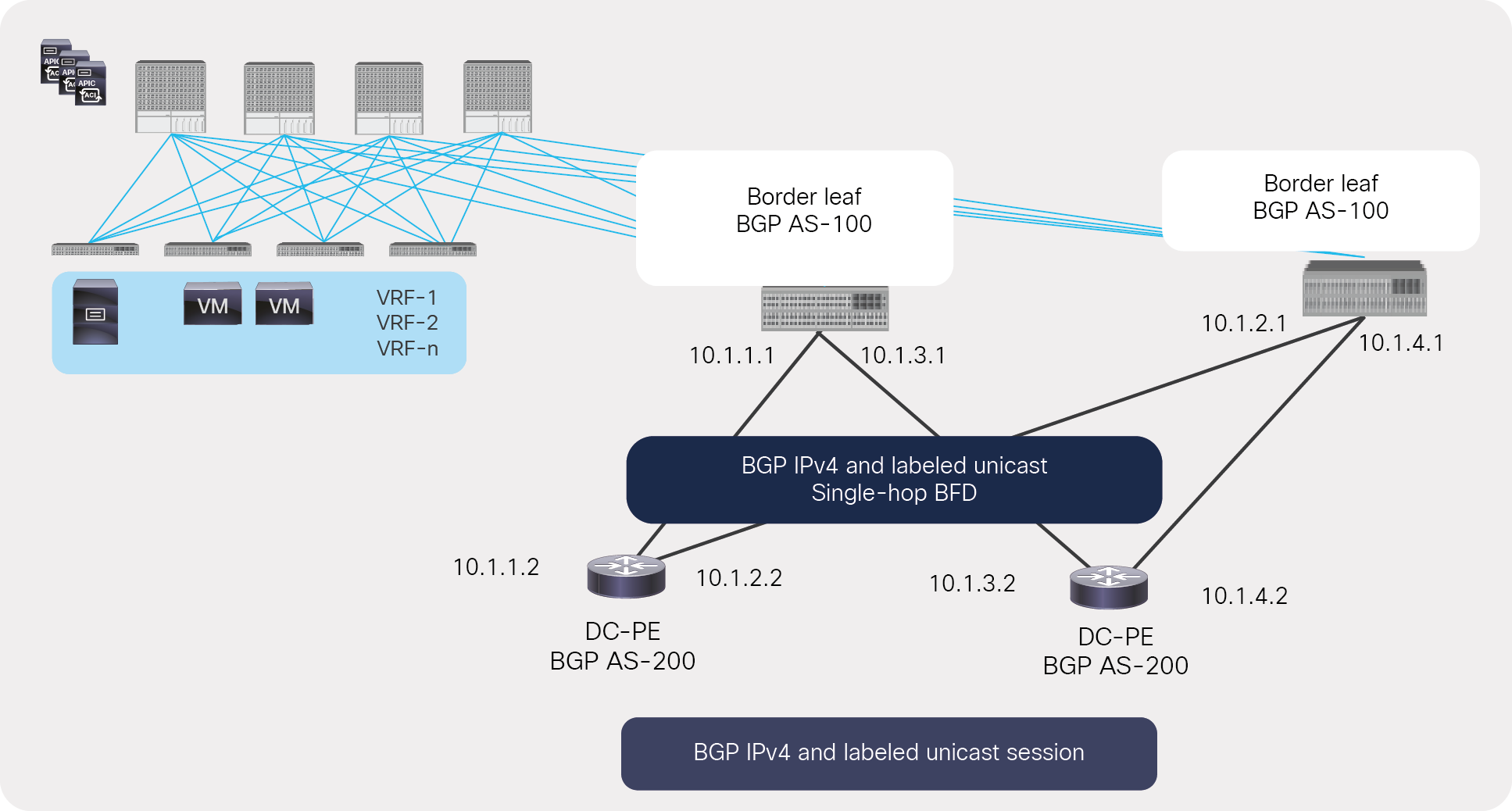
Underlay BGP LU and IPv4 sessions between an ACI border and a next-hop router with single-hop BFD
Segment Routing Global Block (SRGB)
The Segment-Routing Global Block (SRGB) is the range of label values reserved for Segment Routing (SR). These values are assigned as segment IDs (identifiers) (SIDs) to SR-enabled nodes and have global significance throughout the SR domain. SRGB is enabled by default in Cisco ACI with a default SRGB range of 16000 to 23999. If users want to change the default value, it can be modified with a minimum value of 16000 to a maximum value of 471804.
Node Segment ID (SID) of ACI border leaf
Cisco ACI advertises the node SID of the border leaf using BGP-LU. It is advertised as a label index of the transport loopback. The label index of the transport loopback must be unique within an SR domain. All SR routers in the domain use the domain’s SRGB block and label index to calculate the label for the border leaf’s transport loopback.
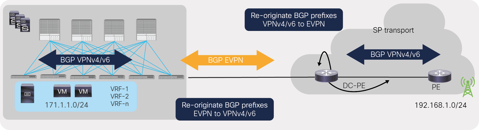
Re-originate BGP EVPN to VPNv4/v6, and VPNv4/v6 to EVPN prefixes on ACI border leaf
The ACI fabric uses the BGP VPNv4/v6 address-family within the fabric to learn external prefixes, and it uses BGP EVPN to exchanges prefixes with the DC-PE. Therefore, it needs to re-originate the EVPN prefixes learned from the DC-PE-to-VPNv4/v6 prefixes and then advertise them within the fabric. Similarly, it needs to re-originate the VPNv4/v6 prefixes learned from the fabric-to-EVPN prefixes and then advertise them to the DC-PE. This is done automatically within ACI.
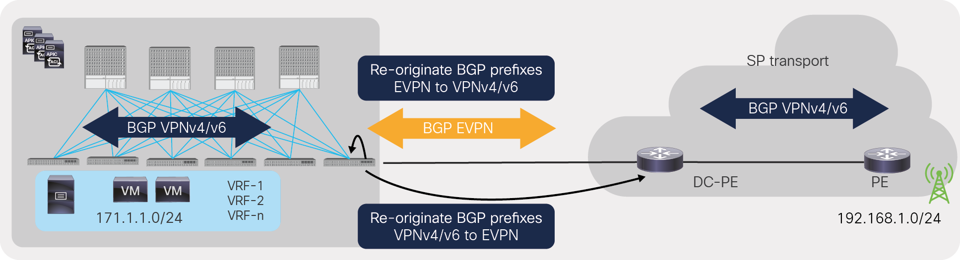
Re-originate BGP EVPN to VPNv4/v6, and VPNv4/v6 to EVPN prefixes on ACI border leaf
Re-originate BGP EVPN to VPNv4/v6, and VPNv4/v6 to EVPN prefixes on DC-PE
The DC-PE typically uses MPLS L3VPN within a transport network, and, for this, it uses the BGP VPNv4/v6 address-family to exchange prefixes, and it uses BGP EVPN to exchange prefixes with ACI border leafs. Therefore, the DC-PE needs to re-originate the EVPN prefixes to VPNv4/v6 prefixes in the transport network and re-originate VPNv4/v6 prefixes to EVPN prefixes toward ACI border leafs.
Re-originate BGP EVPN to VPNv4/v6, and VPNv4/v6 to EVPN prefixes on DC-PE
Configuration model for SR/MPLS handoff
There are two parts to the configuration for SR/MPLS handoff in Cisco ACI. The first part of the configuration is done in Infra Tenant to build BGP-EVPN and BGP-LU connectivity between the ACI border leafs and the DC-PEs to carry all of the VRFs’ prefix information in a single control-plane session. It is highly recommended to use the UI wizard for these configurations, to make sure that all of the configurations can be done without navigating multiple screens.
The second part of the configuration is done in each user tenant to select VRFs and configure routing and security policies. Figure 14 shows all the components required to configure the SR/MPLS handoff.
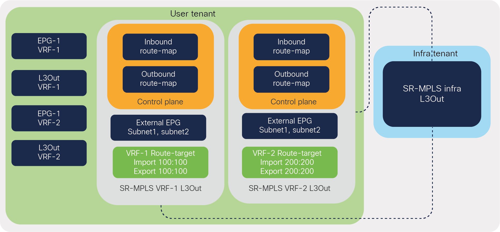
Configuration model for ACI to SR/MPLS handoff
SR-MPLS infra L3Out
SR-MPLS infra L3Out is configured in Infra Tenant on the border leaf to set up the underlay BGP-LU and overlay BGP-EVPN sessions. Infra L3Out can be selectively attached to multiple tenant VRFs to advertise the tenant prefixes to the DC-PE routers and to import prefixes from the DC-PE into the ACI VRFs. Each ACI pod, site, and Remote-Leaf (RL) pair must be configured with a different infra L3Out. However, each pod or RL pair can be configured with multiple infra L3Outs to connect to different routing domains.
ACI SR-MPLS infra L3Out
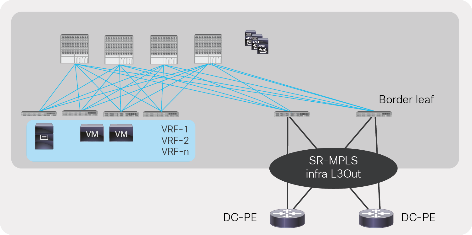
Customers can add multiple border leaf nodes in a single SR-MPLS infra L3Out to add more bandwidth and redundancy toward the DC-PEs. All border leafs work in active/active mode and will be able to forward traffic between the data center and the DC-PEs. All border leaf nodes automatically build BGP EVPN peering with the DC-PEs if they are configured in the same SR-MPLS infra L3Out. Figure 16 shows an example of multiple border leafs in a single SR-MPLS infra L3Out.
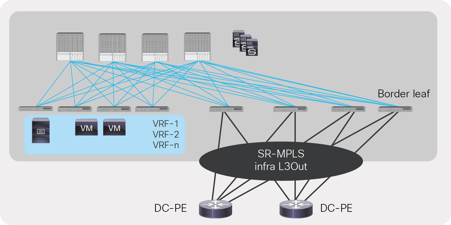
Redundancy and higher bandwidth with multiple border leafs in a single SR-MPLS infra L3Out
Please note that customers can use different SR-MPLS infra L3Outs to separate routing domains. The prefix scale across the fabric can also be improved by distributing VRFs across different border leafs.
SR-MPLS VRF L3Out
Each VRF that needs to be extended toward SR MPLS transport must be configured with SR-MPLS VRF L3Out and attached to an SR-MPLS infra L3Out. By default, all prefixes are imported into the ACI fabric from the SR network, but by using an inbound route-map in VRF L3Out, the user can select the prefixes that need to be leaked to the ACI fabric. The inbound route-map can also be used to apply route policies for prefixes such as setting up a BGP community or changing metrics, AS paths, etc.
An outbound route-map in SR-MPLS VRF L3Out is required. The user needs to explicitly select the ACI fabric prefixes that need to be leaked to the SR network. The outbound route-map is also used to set route policies such as the BGP color community for the prefixes advertised to the SR network. The BGP color community can be used in the SR network to select SR policies. An inbound or outbound route-map can be configured based either on prefixes alone or on prefixes and communities.
VRF L3Out is also configured with an external EPG in which IPv4/IPv6 subnets are used to define security policy, Policy-Based Redirect (PBR), and route leaking between VRFs. As shown in Figure 17, a single VRF L3Out can be associated with multiple SR-MPLS infra L3Outs to advertise prefixes to multiple SR/MPLS routing domains.
SR-MPLS VRF L3Out
BGP route-targets for VRF
VRFs also needs to be configured with route targets in Cisco ACI and matching route targets on the DC-PE to make sure that prefixes are accepted in VRF on the ACI border leaf and the DC-PE. Figure 18 is a snapshot of a route-target configuration in Cisco ACI. This is configured under Tenant->Networking->VRF->Policy->BGP Route Target Profiles.
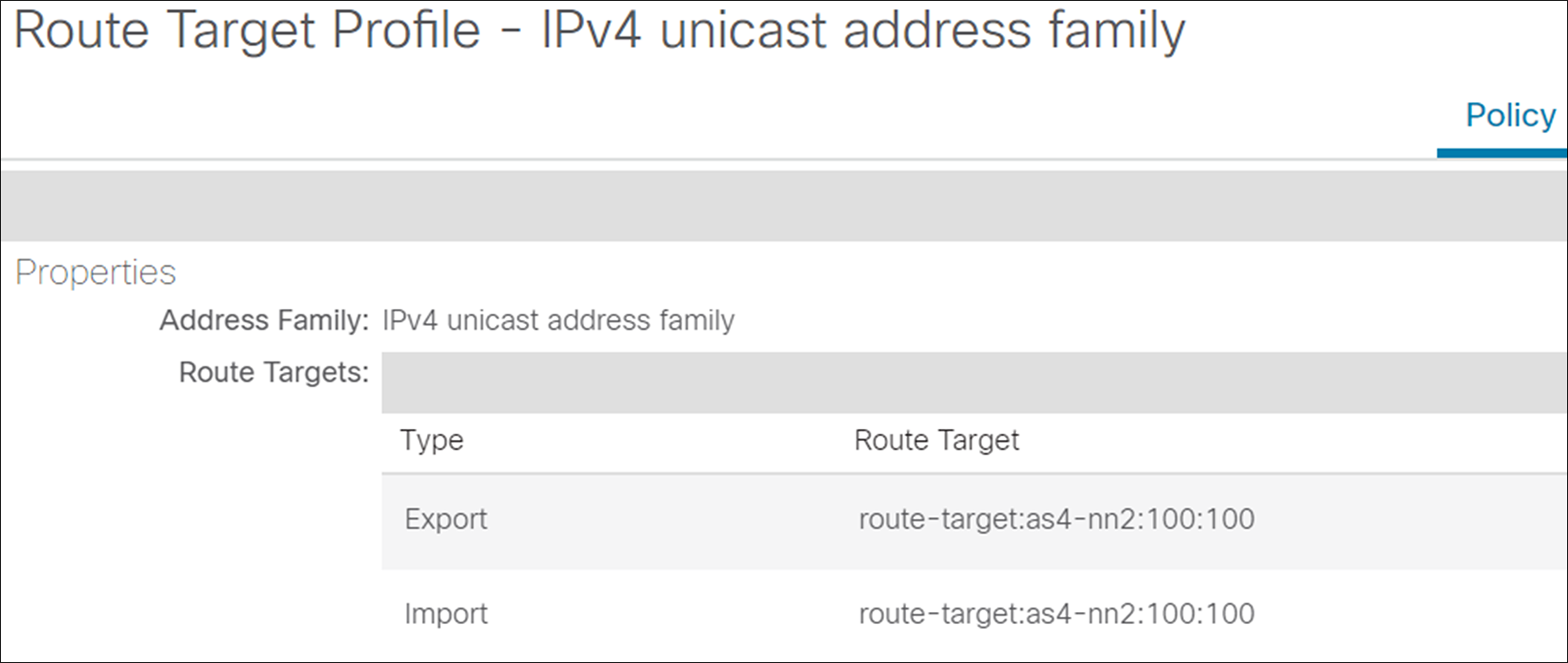
Snapshot of a route-target configuration in Cisco ACI
Configuration for EPG/BD to SR/MPLS L3Out connectivity
The user should configure the following to advertise the EPG/BD prefixes to the SR/MPLS network. Please note that to advertise an EPG/BD prefix, there is no need to associate SR MPLS L3Out to a bridge domain. The user needs to make sure that the outbound route-map is configured correctly to advertise EPG/BD prefixes. Following is the list of configurations that needs to be configured on APIC controller to advertise EPG/BD prefixes to SR/MPLS network.
1. Configure SR-MPLS Infra L3Out on border leafs.
2. Configure SR-MPLS VRF L3Out in the user tenant along with EPGs, bridge domains, and user VRFs.
3. Configure a route-map for exporting and importing of prefixes and apply to SR-MPLS VRF L3Out.
4. Configure the contract and apply it between the EPG and the external EPG defined on SR-MPLS VRF L3Out for traffic forwarding between the EPG and SR-MPLS L3Out.
EPG/BD prefixes advertised through SR-MPLS VRF L3Out
Configuration for IP L3Out to SR/MPLS L3Out
The user should configure the following configurations on APIC controller to advertise L3Out prefixes to the SR/MPLS network:
1. Configure SR-MPLS Infra L3out on border leafs.
2. Configure SR-MPLS VRF L3Out in the user tenant along with IP L3Out and user VRFs.
3. Configure a route map for exporting and importing of prefixes and apply to SR-MPLS VRF L3Out.
4. Configure a contract and apply it between the external EPGs defined on SR-MPLS VRF L3Out and IP L3Out for traffic forwarding between IP L3Out and SR-MPLS L3Out.
IP L3Out prefixes advertised through SR-MPLS VRF L3Out
SR/MPLS label exchange and packet walk
This section explains the MPLS label exchange and packet walks under different scenarios. We will be describing this for the following scenarios:
● Directly connected ACI border leaf and DC-PE
● SR network between ACI border leaf and DC-PE
● MPLS network between ACI border leaf and DC-PE
Directly connected ACI border leaf and DC-PE
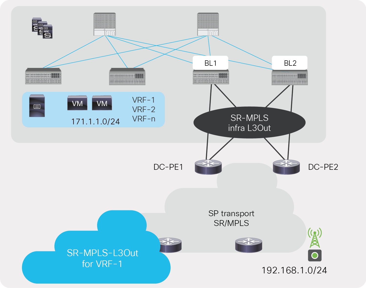
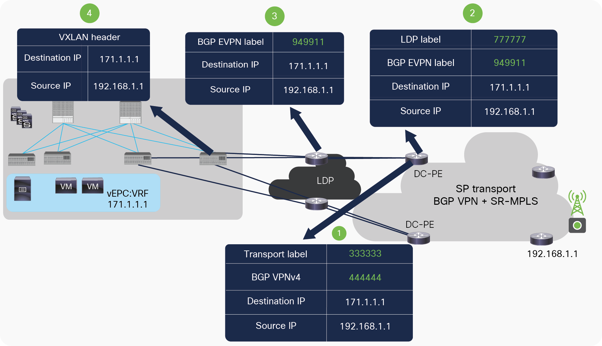
Let’s consider a scenario described below, where prefix 171.1.1.0/24 in vEPC:VRF from the ACI fabric needs to be advertised towards the SR network, and prefix 192.168.1.0/24 from the SR network needs to be advertised in the data center fabric to establish communication. Figure 21 captures the label exchange mechanism when ACI border leaf and the DC-PE are directly connected.
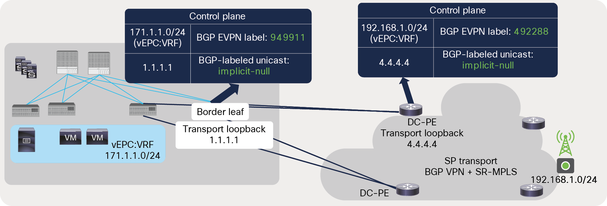
BGP label exchange between directly connected ACI border leaf and DC-PE
Following list describes label exchange mechanism between ACI BL and DC-PE when these are directly connected to each other:
● The ACI border leaf and the DC-PE advertise an implicit-null label for the transport loopback using the BGP-LU address-family. The ACI border leaf advertises an implicit null label for its transport loopback IP 1.1.1.1, and the DC-PE advertises an implicit-null label for its transport loopback 4.4.4.4.
● The ACI border leaf and DC-PE advertise aggregate labels for VRF (vEPC:VRF) using the BGP EVPN address-family. ACI border leaf advertises VRF label 949911, and the DC-PE advertises VRF label 492288.
Figure 22 captures the packet path from the data center fabric to the DC-PE.
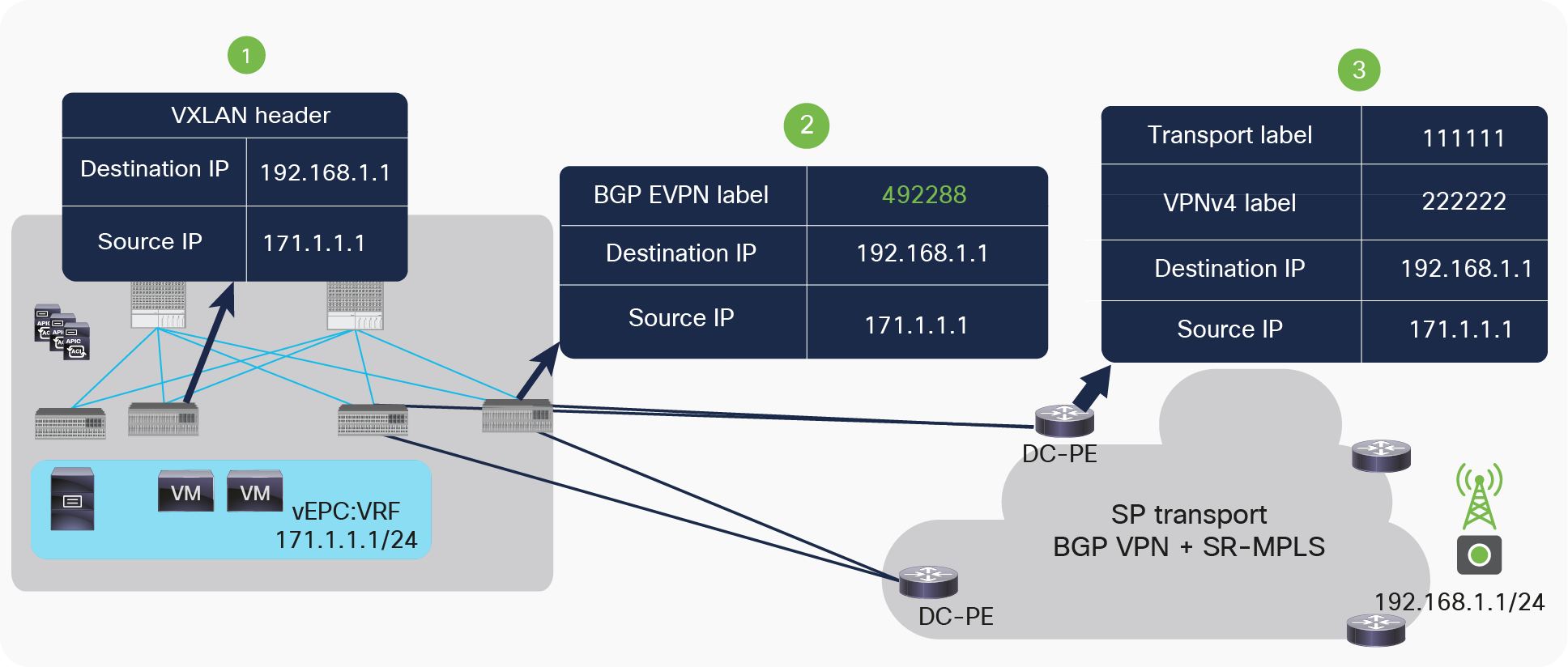
Packet walk from ACI to the DC-PE
Following list describes packet walk from ACI BL to DC-PE when these are directly connected to each other:
● The server connected to the ACI fabric sends the packet to the directly connected ACI server leaf. On receiving the packet, the ACI server leaf does a route lookup in its routing table for the external destination. On route lookup, the ACI server leaf finds that the next hop for the external destination is the border leaf’s TEP address. It then encapsulates the packet with a VXLAN header and sends it to the border leaf.
● The border leaf de-encapsulates the VXLAN packets and does a route lookup for the external destination. It finds the next hop as a loopback IP address of the DC-PE routers reachable through an MPLS-labeled path. It then encapsulates the packet with a VRF label for vEPC:VRF (492288) advertised by the DC-PE for VRF vEPC:VRF using the BGP EVPN address-family. Labeled packets won’t have any outer transport label since an implicit-null was advertised from the DC-PE for transport loopback using the BGP-LU address-family.
● The DC-PE does a lookup for the MPLS label 492288 and finds that the label is mapped to VRF vEPC:VRF. It de-encapsulates the packet and does a route lookup in the VRF routing table. Based on the route lookup, it applies the new VPN and transport label to send the packet to the destination.
Let’s look at packet path from the DC-PE to ACI fabric. Figure 23 captures this.
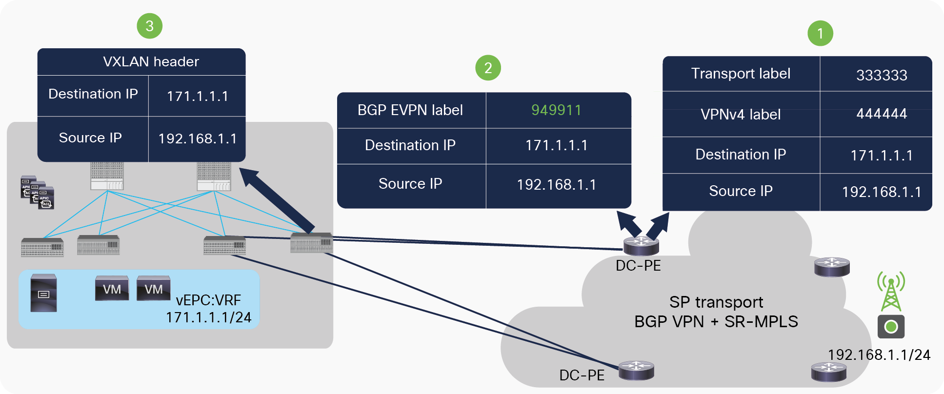
Packet walk from SR-MPLS to ACI network
Following list describes packet walk from DC-PE to ACI BL when these are directly connected to each other:
● The DC-PE receives the MPLS-labeled packet from the SR/MPLS network with VRF and transport label. It does a lookup for the incoming packet’s label and finds that the label is associated with VRF (vEPC:VRF).
● The DC-PE does a route lookup for the destination IP in the VRF table of vEPC:VRF. It finds that the next hop of the destination is a transport loopback IP of the ACI border reachable through an MPLS-labeled path. It encapsulates the packet with a VRF label “949911” advertised by the ACI border leaf for VRF vEPC using the BGP EVPN address-family. Labeled packets won’t have any outer transport label since an implicit-null was advertised from the DC-PE for a transport loopback using the BGL-LU address-family.
● The packet is received by ACI border leaf, which de-encapsulates the packet and does a label lookup for incoming label “949911.” It finds that label is mapped to VRF vEPC:VRF. After de-encapsulation, it does a route lookup for the destination and finds that the next hop is the TEP address of the leaf. It encapsulates the packet with a VXLAN header and sends it to the leaf where the server is connected. This leaf receives the packet, removes the VXLAN header, and sends it to the server.
SR network between ACI border leaf and DC-PE
When there is a SR network between an ACI border leaf and the DC-PE, the label exchange for the VRF remains the same, but the label advertisement for the transport loopback changes. Intermediate routers in the SR network use the label index of the transport loopback and SRGB values to calculate the outer transport label and use it to forward traffic to the DC-PE. Figure 24 explains the label exchange for the transport loopback of the ACI border leaf in the SR domain.
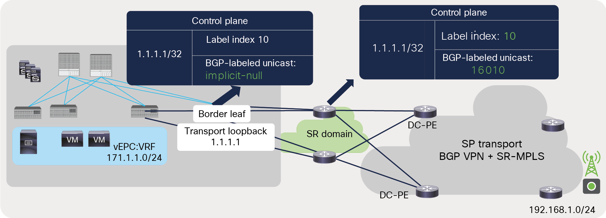
BGP-LU label advertisement from ACI border leaf to DC-PE across an SR-MPLS network
Below list explains the BGP-LU label advertisement from ACI border leaf to DC-PE across an SR-MPLS network:
In Figure 24, 1.1.1.1 is the transport loopback of the border leaf. The ACI border leaf advertises an implicit-null label for the transport loopback to its next-hop router, along with the label index 10.
● The next-hop router uses its SRGB block and label index advertised from the ACI border leaf to calculate the label for the transport loopback of the border leaf. If the SRGB range on the next-hop router is from 16000 to 23999, then the label value advertised from the next-hop router would be 16010, as shown in the figure. It is calculated as a minimum value of the SRGB range plus a label index value; for example, 16000 (the minimum value of SRGB) + 10 (label index) = 16010. This label value for the border leaf’s transport loopback is advertised toward the DC-PE by the next-hop router.
● The SRGB range should be the same across the whole SR domain; as a result, all routers in the SR domain will have the same label value for the transport loopback of the ACI border leaf.
Let’s look at Figure 25 to understand the BGP-LU label advertised from the DC-PE toward the border leaf with an SR-MPLS network in between.
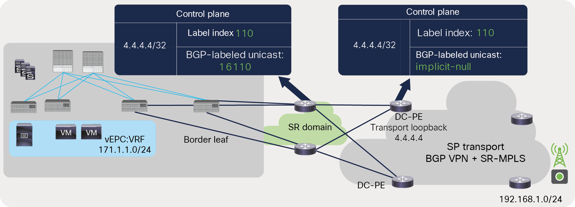
BGP-LU label advertisement from DC-PE to ACI border leaf across an SR-MPLS network
Following list describes BGP-LU label advertisement from DC-PE to ACI border leaf across an SR-MPLS network:
● In Figure 25, 4.4.4.4 is the transport loopback of the DC-PE. The DC-PE advertises an implicit-null label for the transport loopback to its next-hop router, along with the label index 110.
● The next-hop router uses its SRGB block (16000—23999) and the label index (110) advertised from the DC-PE to calculate the label (16110) for the transport loopback of the DC-PE, and advertises it toward the ACI border leaf.
BGP-LU must be configured between the ACI border leaf and the next-hop router (DC-P), but a different routing protocol can be used between the DC-P and the DC-PE. Therefore, there needs to be route redistribution on DC-P between the BGP-LU and IGP SR for reachability of the transport loopback between the ACI border leaf and the DC-PE. Figure 26 shows this scenario.
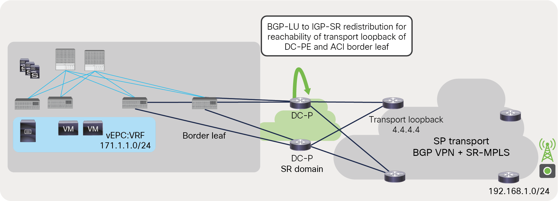
BGP-LU to IGP-SR redistribution
Let’s look at a packet flow from the ACI fabric to the SR/MPLS network (Figure 27).
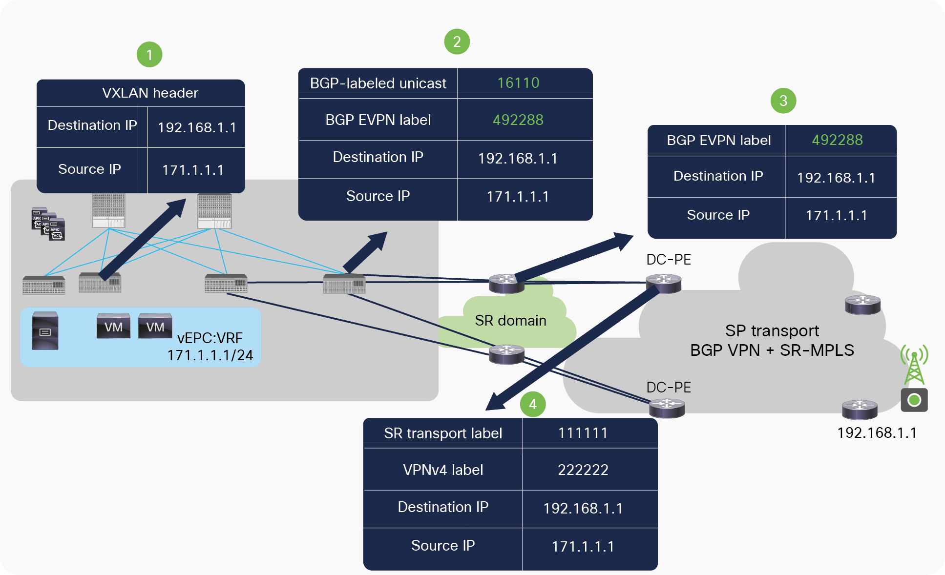
Packet flow from ACI fabric to DC-PE across SR-MPLS network
Following list explains the packet flow from ACI fabric to DC-PE across SR-MPLS network:
● The server connected to the ACI fabric sends the packet to the directly connected ACI leaf. On receiving the packet, the ACI leaf does a route lookup in its routing table for the external destination. On route lookup, the ACI leaf finds that the next hop for the destination is the border leaf’s TEP address. It then encapsulates the packet with a VXLAN header and sends it to the border leaf.
● The border leaf de-encapsulates the VXLAN packets, and does a route lookup for the external destination. It finds that the next hop is the loopback IP address of the DC-PE routers reachable through an MPLS-labeled path. It then encapsulates the packet with two labels. The inner label will be a VRF label for vEPC:VRF (492288) advertised by the DC-PE for VRF vEPC:VRF using the BGP EVPN address-family. The outer label will be 16110, which is for the transport loopback of the DC-PE advertised by the next-hop router using the BGP-LU address-family.
● On receiving a packet with the label 16110, the next-hop router in the SR network will remove the outer label 16110 and send the packet with only the VRF label 492288. The next-hop router may swap the label 16110 with another outer label if the DC-PE router is not directly connected to it.
● The DC-PE does a lookup for the MPLS label 492288. It finds that the label is mapped to VRF vEPC:VRF. It de-encapsulates the packet and does a route lookup in the VRF routing table. Based on the route look up, it applies the new VPN and transport label to send the packet to the destination.
Let’s look at a packet walk in the reverse direction, from the DC-PE to the ACI fabric (Figure 28).
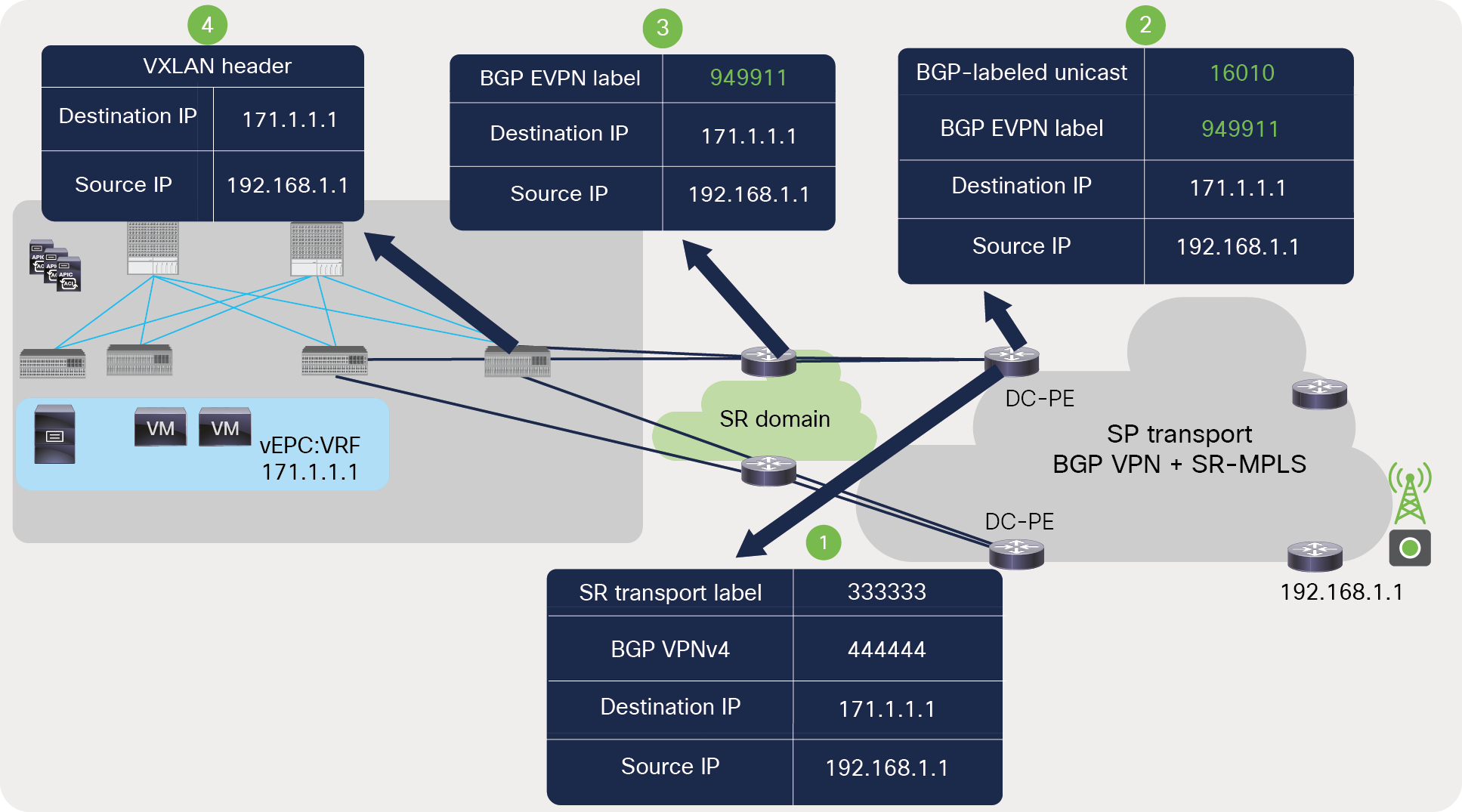
Packet walk from DC-PE to ACI fabric across SR-MPLS network
Following list explains the packet flow from DC-PE to ACI fabric across SR-MPLS network:
● The DC-PE receives the MPLS-labeled packet from the SR/MPLS network with a VRF and transport label. It does a lookup for the incoming packet’s label and finds that the label is associated with a VRF (vEPC:VRF).
● The DC-PE de-encapsulates the labeled packet coming from the transport network and does a route lookup for the destination IP in the VRF table of vEPC:VRF. It finds that the next hop of the destination is a transport loopback IP of the ACI border leaf reachable through an MPLS-labeled path. It encapsulates the packet with two labels. The inner label will be a VRF label “949911” advertised by ACI border leaf for VRF vEPC, using the BGP EVPN address-family. The outer label will be 16010, which is for the transport loopback of the DC-PE advertised by the next-hop router using the BGP-LU address-family.
● On receiving a packet with the label “16010,” the next-hop router in the SR network will remove the outer label “16010” and send the packet with only the VRF label, “949911.” The next-hop router may swap the label 16010 with another outer label if the ACI border leaf is not directly connected to it.
● After receiving the packet, the ACI border leaf de-encapsulates the packet and does a label lookup for the incoming label “949911.” It finds that the label is mapped to VRF vEPC:VRF. It does a route lookup for the destination in VRF vEPC:VRF and finds that the next hop is the TEP address of the leaf. It encapsulates the packet with the VXLAN header and sends it to the leaf where the server is connected. This leaf receives the packet, removes the VXLAN header, and sends it to the server.
MPLS network between ACI border leaf and DC-PE
Even though the ACI border leaf doesn’t support MPLS LDP, Cisco ACI to SR-MPLS handoff provides a solution for the transport network that doesn’t support segment routing. Customers can enable SR-MPLS handoff from Cisco ACI with MPLS mode. In this mode, the ACI border leaf doesn’t advertise the label index of the node to its next-hop router. The next-hop router or the DC-PE doesn’t need to understand the label index or SR; it can use the label received from the ACI border leaf using BGP-LU for underlay connectivity between the ACI border leaf and the DC-PE. Figure 29 shows a snapshot of the Cisco APIC screen for enabling BGP-LU connection in MPLS mode.
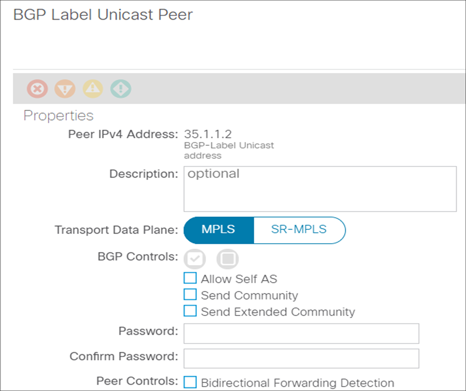
Configuration snapshot from APIC controller to enable SR/MPLS handoff in SR-MPLS or MPLS mode
Customers can also use LDP between the next-hop router of the ACI border leaf and the DC-PE. In this case, the label exchange for the VRF remains the same, using the BGP EVPN address-family, but the label advertisement for the transport loopbacks between the next-hop router and the DC-PE uses LDP. Figure 30 explains the label exchange for transport loopback of the ACI border leaf when the MPLS LDP network is used in between the ACI border leaf and the DC-PE.
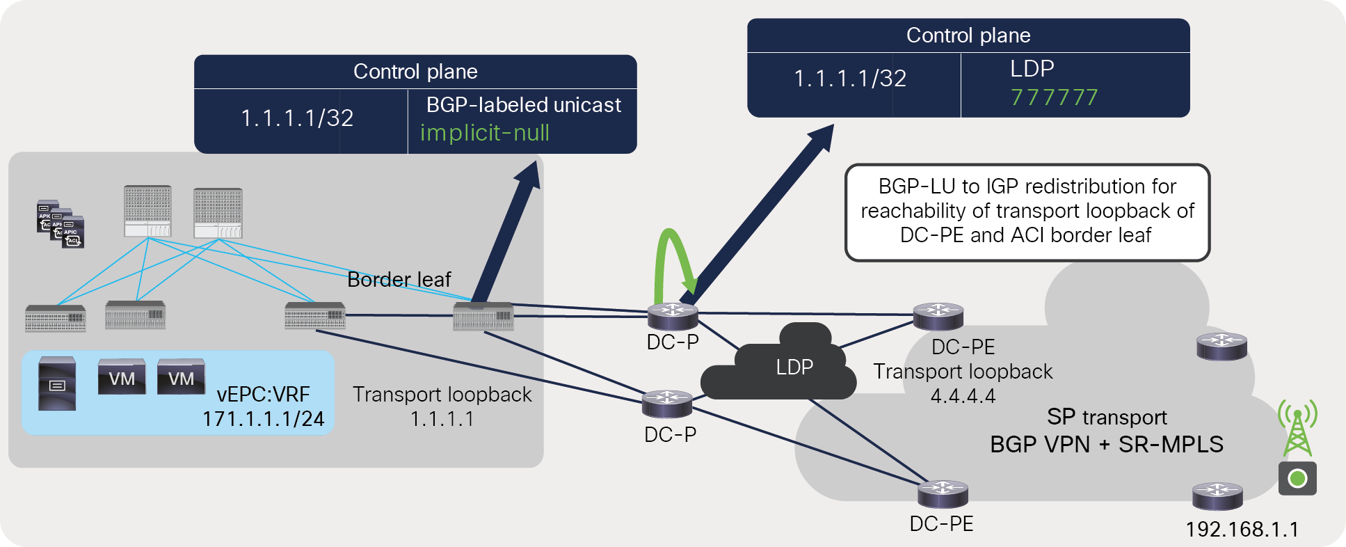
Label advertisement for ACI border leaf’s transport loopback across MPLS LDP network
Following list explains the label exchange for transport loopback of ACI BL across MPLS LDP network to DC-PE:
● In Figure 30, 1.1.1.1 is the transport loopback of the border leaf. The ACI border leaf advertises an implicit-null label for the transport loopback to its next-hop (DC-P) using BGP-LU address-family.
● The next-hop router (DC-P) is running LDP toward the DC-PE router; it advertises the LDP label 777777 for 1.1.1.1. It will also redistribute prefix 1.1.1.1 learned from the BGP-LU to IGP protocol running toward the DC-PE if BGP-LU is not used between the DC-P and the DC-PE. If BGP-LU is used, end-to-end prefix redistribution is not required.
Figure 31 explains the label exchange for the transport loopback of the DC-PE when the MPLS LDP network is used between the ACI border leaf and the DC-PE.
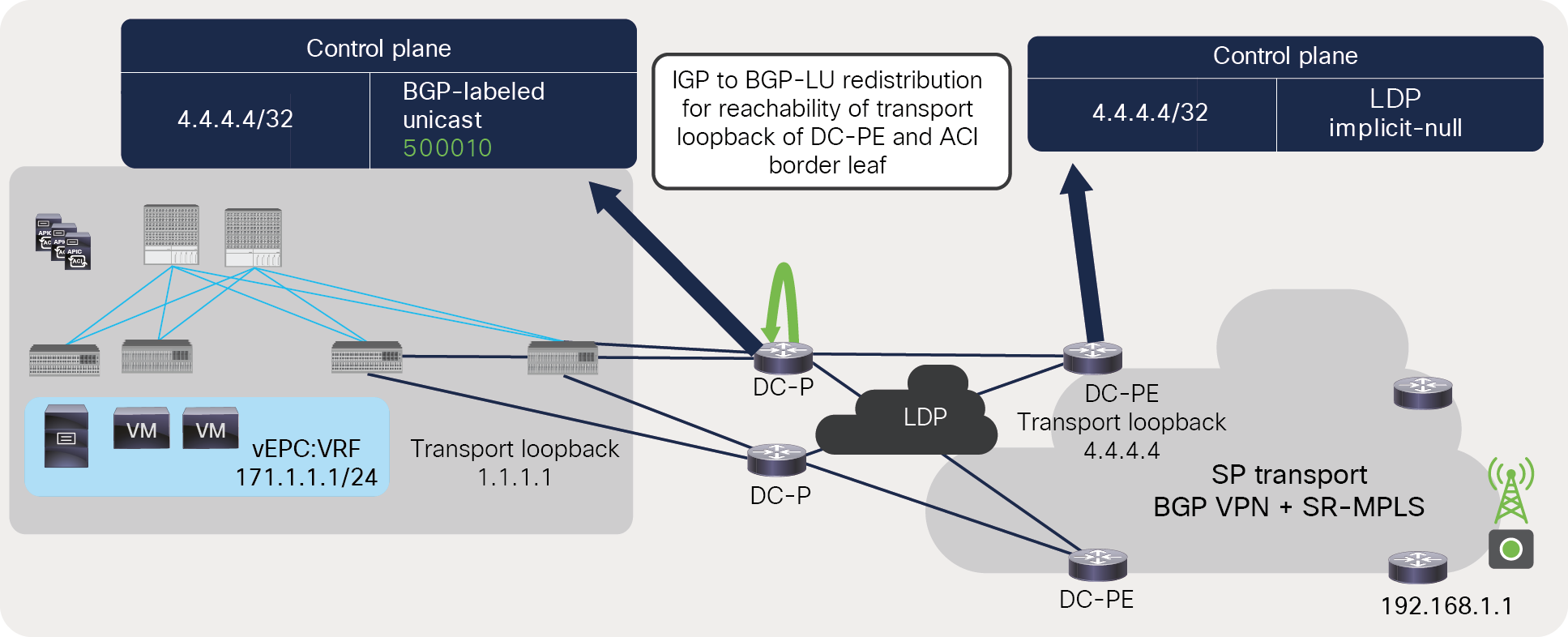
Label advertisement for DC-PE’s transport loopback across MPLS LDP network
Following list explains the label exchange for transport loopback of DC-PE across MPLS LDP network to ACI BL:
● In Figure 31, 4.4.4.4 is the transport loopback of the DC-PE. The DC-PE advertises an implicit-null label for the transport loopback to its next-hop router using LDP.
● The next-hop router (DC-P) in Figure 31 may receive an implicit-null for the transport loopback of the DC-PE if it is directly connected to it. But if it’s not directly connected to the DC-PE, then it may receive another label, such as “666666,” for the transport loopback of the DC-PE. The DC-P will also redistribute the prefixes received from the DC-PE using IGP to BGP-LU. If BGP-LU is used, end-to-end prefix redistribution is not required.
● The DC-P uses BGP-LU and advertises “500010” as a label for the transport loopback of the DC-PE using the BGP-LU address-family toward the ACI border leaf.
Figure 32 captures the packet from the ACI fabric to the SR/MPLS network when LDP is used between the ACI border leaf and the DC-PE.
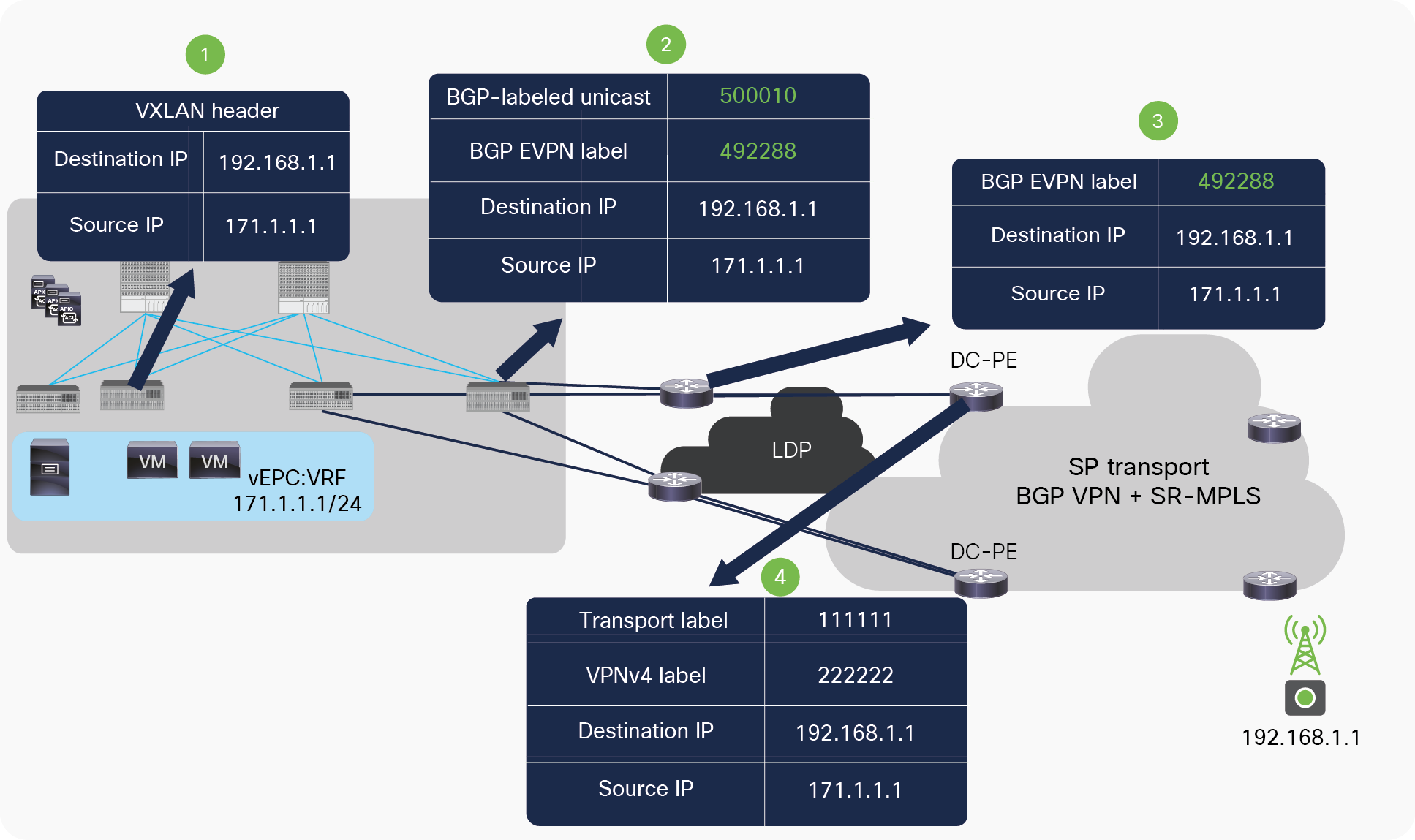
Packet walk from ACI fabric to DC-PE across MPLS LDP network
Following list explains the packet walk from ACI BL to DC-PE across MPLS LDP network:
● The server connected to the ACI fabric sends the packet to the directly connected ACI leaf. On receiving the packet, the ACI leaf does a route lookup in its routing table for the external destination. On route lookup, the ACI leaf finds that the next hop for the destination is the border leaf’s TEP address. It then encapsulates the packet with a VXLAN header and sends it to the border leaf.
● The border leaf de-encapsulates the VXLAN packets and does a route lookup for the external destination. It finds the next-hop as the loopback IP address of the DC-PE routers reachable through an MPLS-labeled path. It then encapsulates packet with two labels. The inner label will be a VRF label for vEPC:VRF (492288) advertised by the DC-PE for VRF vEPC:VRF using the BGP EVPN address-family. The outer label will be “500010,” which is for the transport loopback of the DC-PE advertised by the next-hop router (DC-P) using the BGP-LU address-family.
● On receiving a packet with label “500010,” the next-hop router (DC-P) removes the outer label and sends the packet with only the VRF label to the DC-PE if it is directly connected to the DC-PE. Otherwise, it may swap the label 500010 with another outer label, such as “666666.”
● The DC-PE does a lookup for the MPLS label 492288 and finds that the label is mapped to VRF vEPC:VRF. It de-encapsulates the packet and does a route lookup in the VRF routing table of vEPC:VRF. Based on the route lookup, it applies the new VPN and transport label to send the packet to the destination.
Let’s look at a packet walk in the reverse direction. Figure 33 captures a packet walk from SR/MPLS to the ACI fabric when LDP is used between an ACI border leaf and a DC-PE.
Packet walk from DC-PE to ACI fabric across MPLS LDP network
Following list explains the packet walk from DC-PE to ACI BL across MPLS LDP network:
● The DC-PE receives the MPLS-labeled packet from the SR/MPLS network with a VPN and transport label. It does a lookup for the incoming packet’s label and finds that the label is associated with a VRF (vEPC:VRF).
● The DC-PE de-encapsulates the incoming labeled packet and does a route lookup for the destination IP in the VRF table of vEPC:VRF. It finds that the next hop of the destination is a transport loopback IP of the ACI border leaf reachable through an MPLS-labeled path. It encapsulates the packet with two labels. The inner label would be VRF label “949911,” advertised by the ACI border leaf for VRF vEPC using the BGP EVPN address-family. The outer label will be “777777,” which is for the transport loopback of the ACI border leaf advertised by the next-hop router (DC-P) using LDP.
● The packet is received by the DC-P with the outer label “777777”; it removes the outer label and sends the packet with only the VRF label “949911” to the ACI border leaf.
● The packet is received by the ACI border leaf, which does a label lookup for the incoming label “949911.” It finds that the label is mapped to VRF vEPC:VRF. It de-encapsulates the packet and does a route lookup for the destination and finds that the next hop is the TEP address of the leaf. It encapsulates the packet with a VXLAN header and sends it to the leaf where the server is connected. This leaf receives the packet, removes the VXLAN header, and sends it to the server.
Cisco ACI–distributed data centers with SR-MPLS
Customers are building Cisco ACI–based data centers across multiple geographically distributed on-premises and cloud locations. Cisco ACI allows them to apply consistent policy across on-premises, remote, and cloud-based workloads. Cisco ACI provides this solution using Multi-Site, Multi-Pod, and remote leafs. The SR/MPLS handoff solution is supported with all of these options.
SR/MPLS with Cisco ACI remote leafs
Cisco ACI remote leafs provide centralized management and consistent policy for multiple small and remote data centers, such as telco edge data centers. In this solution, the APIC and spines remain in the main central data center, and only remote leaf switches are deployed in the remote edge data center. Configuration pushes, policy pushes, upgrades, downgrades, operations, etc., for the remote leaf are performed by the APIC located in the main data center. Remote leaf switches forward traffic locally, and failure of the APIC and spines in the main data center does not stop traffic forwarding at the remote leaf. As with a regular leaf, you can connect any type of workload, such as bare-metal, virtual machines, containers, and routers, to a remote leaf, and you have the same features and functionalities as a local leaf connected in the main data center. Remote leaf switches connect to the APIC and spine in the main data center using a Layer 3 IP network, as shown in Figure 34.
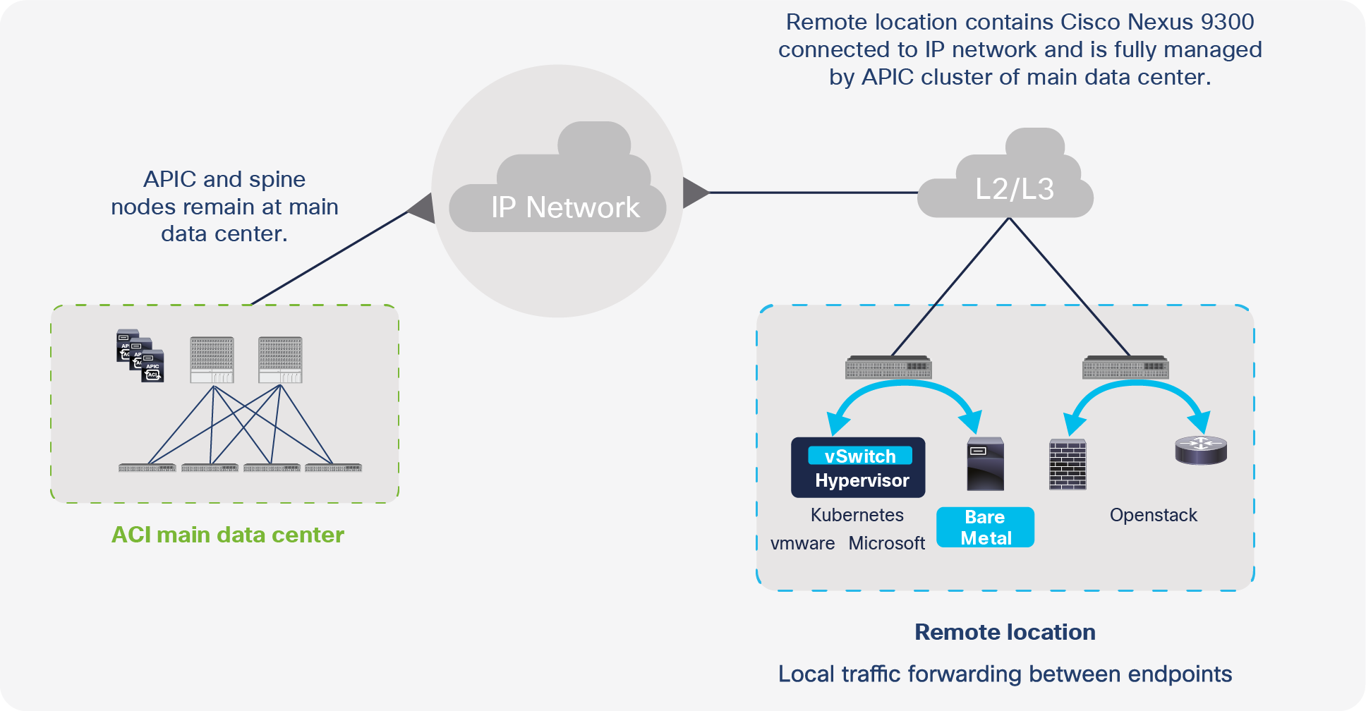
Cisco ACI remote leaf architecture
SR/MPLS handoff can be configured on a remote leaf as well as the main data center border leaf. To use this solution, the remote leaf and on the border leaf in the main data center each must be configured with a different SR/MPLS infra L3Out.To use an SR/MPLS path for communication between the ACI main data center and the remote leaf instead of the IP Network (IPN) between the spine and the remote leaf, the following must be done:
● Different VRFs need to be configured on the ACI remote leaf pairs and on the ACI main data center pods.
● There must be no contracts between the EPGs in the remote leaf and in the main data center in a different VRF.
Let’s understand these in detail.
The reason for needing different VRFs on ACI remote leaf pairs and ACI main data center pods for traffic forwarding over an SR/MPLS path.
When the same VRF is configured on both the remote leaf and the ACI main data center, both the remote leaf and the border leaf will learn each other’s prefixes directly over the IPN. Therefore, the ACI border leaf and remote leaf will prefer the internal path over the IPN to forward traffic to each other. This traffic will be encapsulated with VXLAN headers. This behavior is shown in Figure 35.
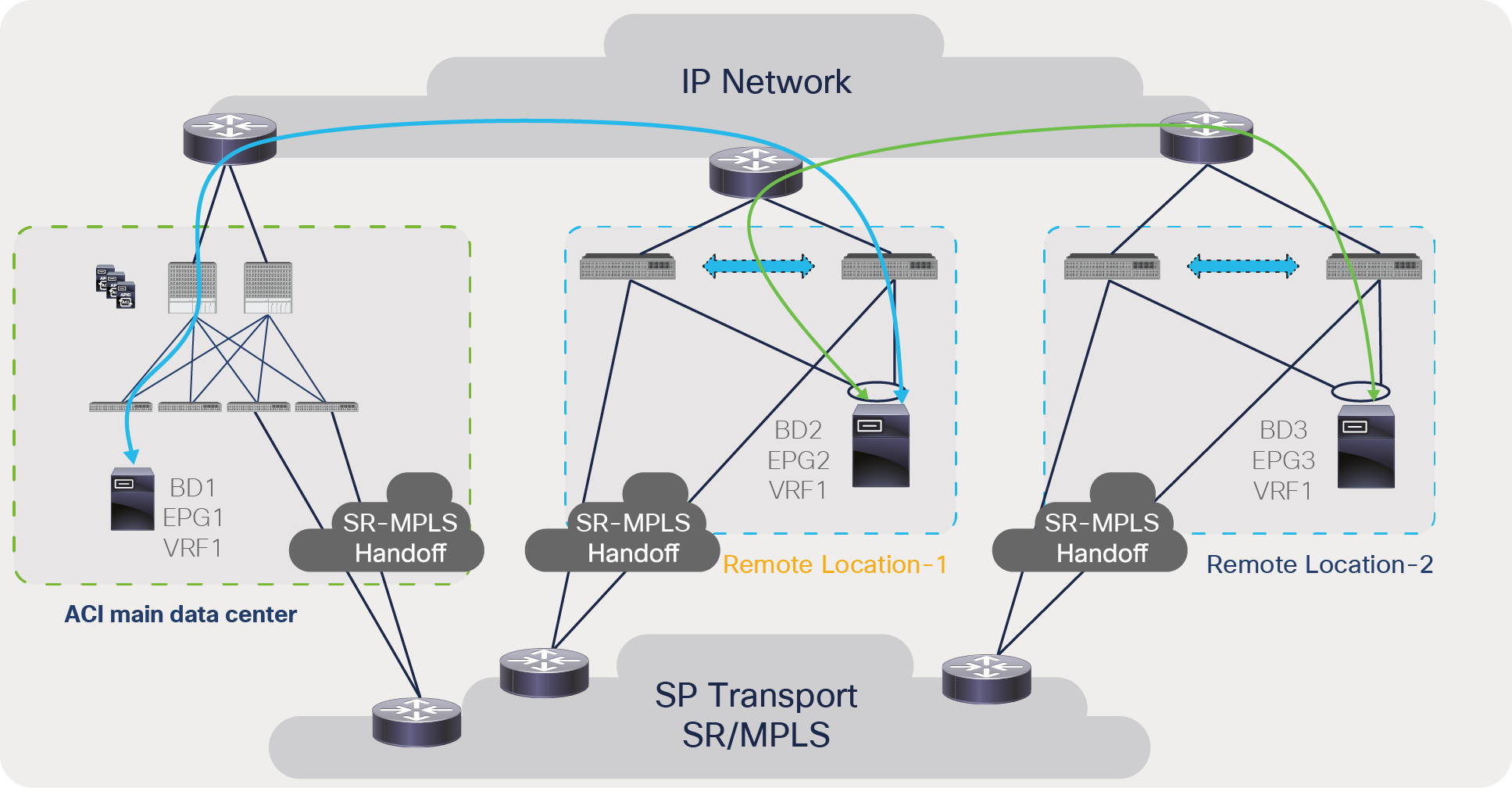
Traffic forwarding between ACI border leaf and remote leaf when the same VRF is deployed on both devices
To avoid this behavior, each remote-leaf pair and the ACI main data center can be configured with different VRFs. On the DC-PE, these VRFs can be mapped to a common VRF, as shown in Figure 36. With this approach, the ACI border leaf will have the reachability to the remote-leaf prefixes via the SR/MPLS path only. Similarly, the remote-leaf pair will have reachability to the ACI main data center or another remote-leaf pair via the SR/MPLS path only. Due to this approach, all traffic between the ACI main data center and the remote leaf and between remote-leaf pairs will be encapsulated with SR/MPLS.
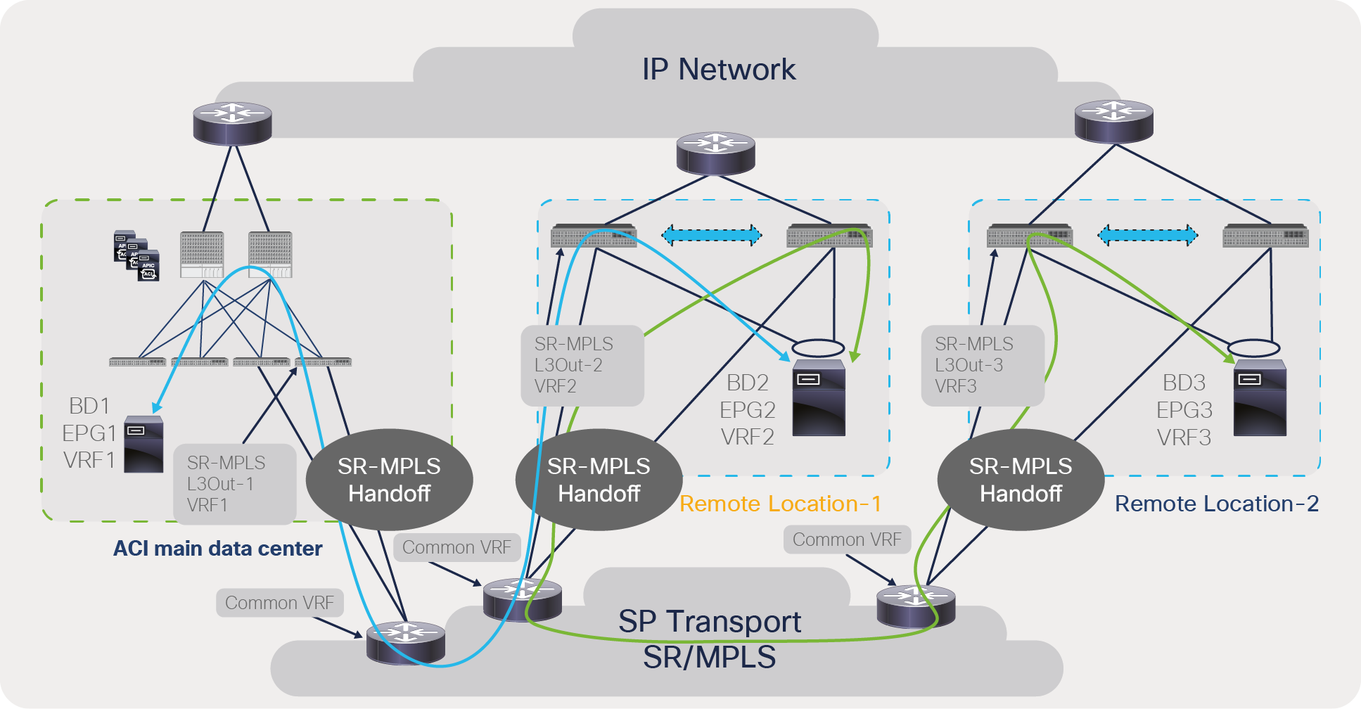
Traffic forwarding between ACI border leaf and remote leaf when a different VRF is deployed on both devices
As shown in Figure 36, the ACI main data center is configured with VRF1, Remote Location-1 is configured with VRF2, and Remote Location-2 is configured with VRF3. At all of these locations, these VRFs (VRF1, VRF2, and VRF3) are mapped to a common VRF on a DC-PE. Due to this configuration, the traffic path between the different locations will be via the SR/MPLS handoff path only; therefore, traffic will be forwarded via the SR/MPLS path and not via the IPN.
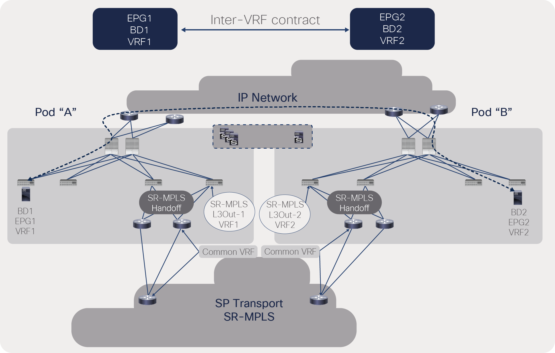
Reason for having no contracts between EPGs of the remote leaf and the main data center in a different VRF for traffic forwarding via an SR/MPLS path.
When contracts are configured between EPGs that are in different VRFs, routes are leaked between the VRFs. Therefore, even if the main data center and the remote leaf are configured with different VRFs, the contract between these VRFs will leak routes across the VRFs.
Let’s understand this with the example shown in Figure 37. The ACI main data center is configured with VRF1, Remote Location-1 is configured with VRF2, and Remote Location-2 is configured with VRF3. In this example, EPG1 of VRF1 in the main data center has a contract with EPG2 of VRF2 in the remote leaf. Because of this configuration, VRF1 in the main data center will get direct reachability to VRF2’s prefixes via the IPN path, and ACI will prefer this path. Similarly, VRF2 in the remote leaf will get direct reachability to VRF1’s prefixes via the IPN path, and ACI will prefer this path. Figure 37 shows this behavior.
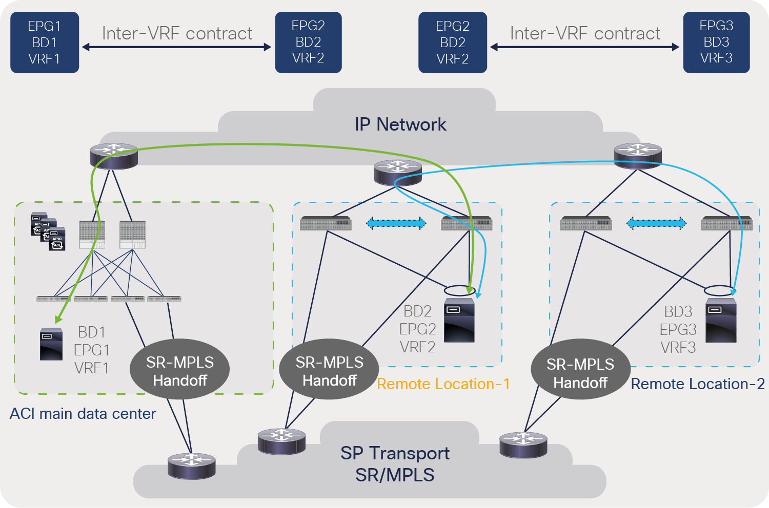
Traffic forwarding between ACI border leaf and remote leaf when inter-VRF contracts are configured
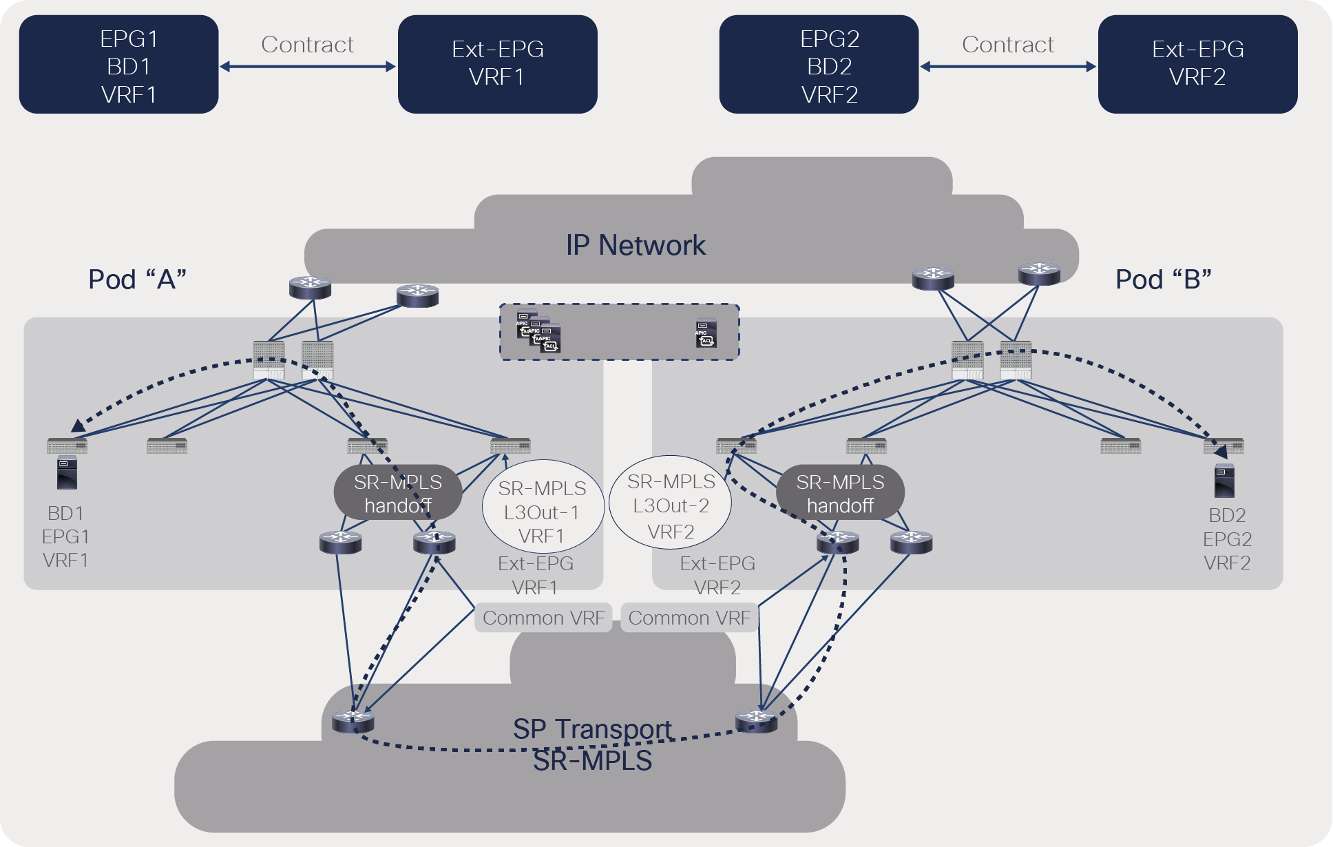
To avoid this situation, the user should configure the contract with a local external EPG in its own VRF, as shown in Figure 38. This will ensure that connectivity is always via the SR/MPLS path and that there is no route leaking across VRFs.
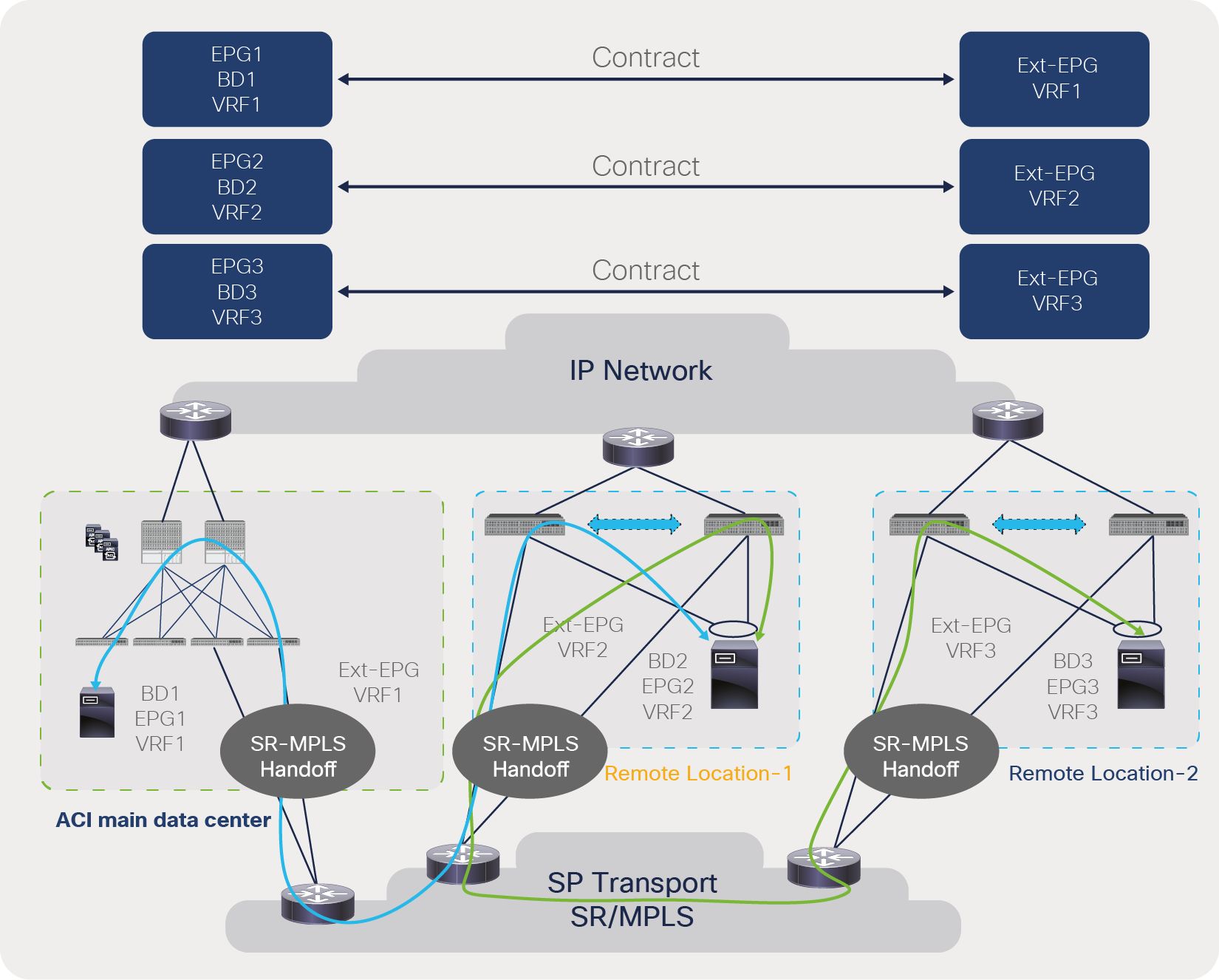
Traffic forwarding between ACI border leaf and remote leaf when contracts are configured within a locally configured VRF
Customers can select the VRF where they need to stretch objects such as an EPG; traffic for these VRFs will go over the IPN. VRFs that require traffic path via the SR/MPLS should not use inter-VRF contracts or stretching of a VRF. In Figure 39, communication between VRF1 and VRF2 happens via the SR/MPLS because these VRFs are not stretched. Communication within VRF1 happens via the IPN because the VRF is stretched.

Traffic path selection between IPN and SR/MPLS for a VRF
SR/MPLS with Cisco ACI Multi-Pod
The Cisco ACI Multi-Pod solution allows customer to manage multiple ACI pods through a single APIC cluster and build consistent policy across these pods. The pods can be within the same data center or geographically distributed within 50msec of round-trip latency. From the control-plane point of view, each pod has a separate control plane (ISIS and COOP) and uses BGP EVPN to provide connectivity between pods. Pods are connected through a Layer-3 IP Network (IPN), and traffic between pods is encapsulated with VXLAN headers. Cisco ACI Multi-Pod also builds L2/L3 connectivity between pods to provide workload mobility. Figure 40 provides an overview of this solution.
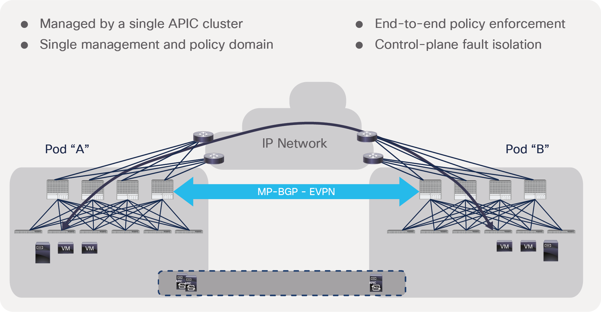
Cisco ACI Multi-Pod overview
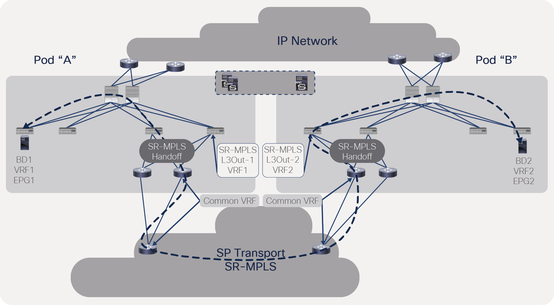
SR/MPLS handoff can be configured on each pod, and inter-pod traffic can be forwarded through the SR/MPLS path instead of the VXLAN path through the IPN. Please note that a separate SR/MPLS infra L3Out must be configured in each pod. To use the SR/MPLS path for communication between ACI pods, the following must be done:
● A separate VRF needs to be configured on each ACI pod.
● No contracts are allowed between EPGs in the different VRFs across pods.
As explained in the remote leaf section, if a separate VRF is deployed in each pod, inter-pod prefixes will be reachable via SR/MPLS L3Outs. This will force inter-pod traffic to get forwarded through the SR/MPLS network. Figure 41 shows this behavior.
Traffic forwarding between ACI pods with a separate VRF in each pod
As explained in the remote leaf section, inter-VRF contracts will cause route-leaking between VRFs and will force traffic to go over the IPN path, as shown in Figure 42.
Traffic forwarding between ACI pods with an inter-VRF contract between pods
To force traffic to go over the SR/MPLS path, the user must ensure that contracts are configured with local external EPGs instead of inter-VRF contracts.
Traffic forwarding between ACI pods with the same VRF contract
Customers can select the VRF where they need to stretch objects such as EPGs; traffic for these VRFs will go over the IPN. While VRFs that require a traffic path through the SR/MPLS should not use an inter-VRF contract or a stretched VRF. In Figure 44, communication between VRF1 and VRF2 happens via the SR/MPLS because these VRFs are not stretched. Communication within VRF3 happens via the IPN because the VRF is stretched.
Traffic path selection between IPN and SR/MPLS for a VRF
SR/MPLS with Cisco ACI Multi-Site
In Cisco ACI Multi-Site solution, Multi-Site Orchestrator (MSO) manages multiple fabrics (ACI sites) with a single point of management and consistent policy across geographically dispersed locations. Each site has independent APIC clusters that are completely isolated from each other to offer a true disaster-recovery solution. MSO can push ACI policies including SR/MPLS configurations across multiple sites. Figure 45 shows the architecture of the Cisco ACI Multi-Site solution.
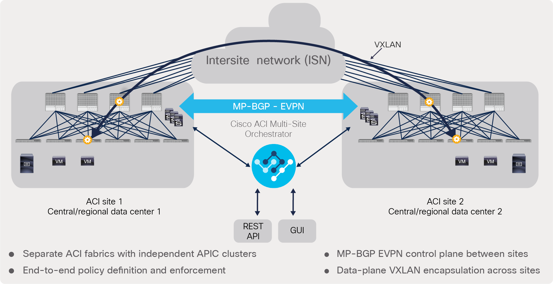
Cisco ACI Multi-Site architecture
By default, communication between sites uses VXLAN just like the Cisco ACI Multi-Pod or remote leaf solution. SR/MPLS handoff can be configured on each ACI site, and inter-pod traffic can be forwarded through the SR/MPLS path instead of the VXLAN path through intersite network (ISN). Please note that separate SR/MPLS infra L3Outs must be configured in each site. To use the SR/MPLS path for communication between ACI sites, the following must be done:
● A separate VRF needs to be configured on each ACI site.
● No contracts are allowed between the EPGs in different VRFs across sites.
As explained in the remote leaf and Cisco ACI Multi-Pod sections, if a separate VRF is deployed in each site, intersite prefixes will be reachable through SR/MPLS L3Outs. This will force intersite traffic to be forwarded through the SR/MPLS network. Figure 46 shows this behavior.
Traffic forwarding between Cisco ACI sites with a separate VRF in each site
As explained in the remote leaf and Cisco ACI Multi-Pod sections, an inter-VRF contract will cause route-leaking between VRFs and will force traffic to go over the ISN path. To force traffic to go over the SR/MPLS path, the user must ensure that contracts are configured with local external EPGs instead of inter-VRF contracts. Figure 47 shows this behavior.
Traffic forwarding between Cisco ACI sites with the same VRF contract
As with ACI Multi-Pod and remote leaf, customers can select a VRF where they need to stretch objects such as EPGs; the traffic for these VRFs will go over the ISN. VRFs that require a traffic path through SR/MPLS should not use an inter-VRF contract or a stretched VRF.
From Cisco ACI Release 5.0 onward, customers can deploy Cisco ACI Multi-Site if all of the traffic requirements are through SP transport and there is no requirement for VRF stretching across sites. (See Figure 48.)
Cisco ACI Multi-Site without intersite network
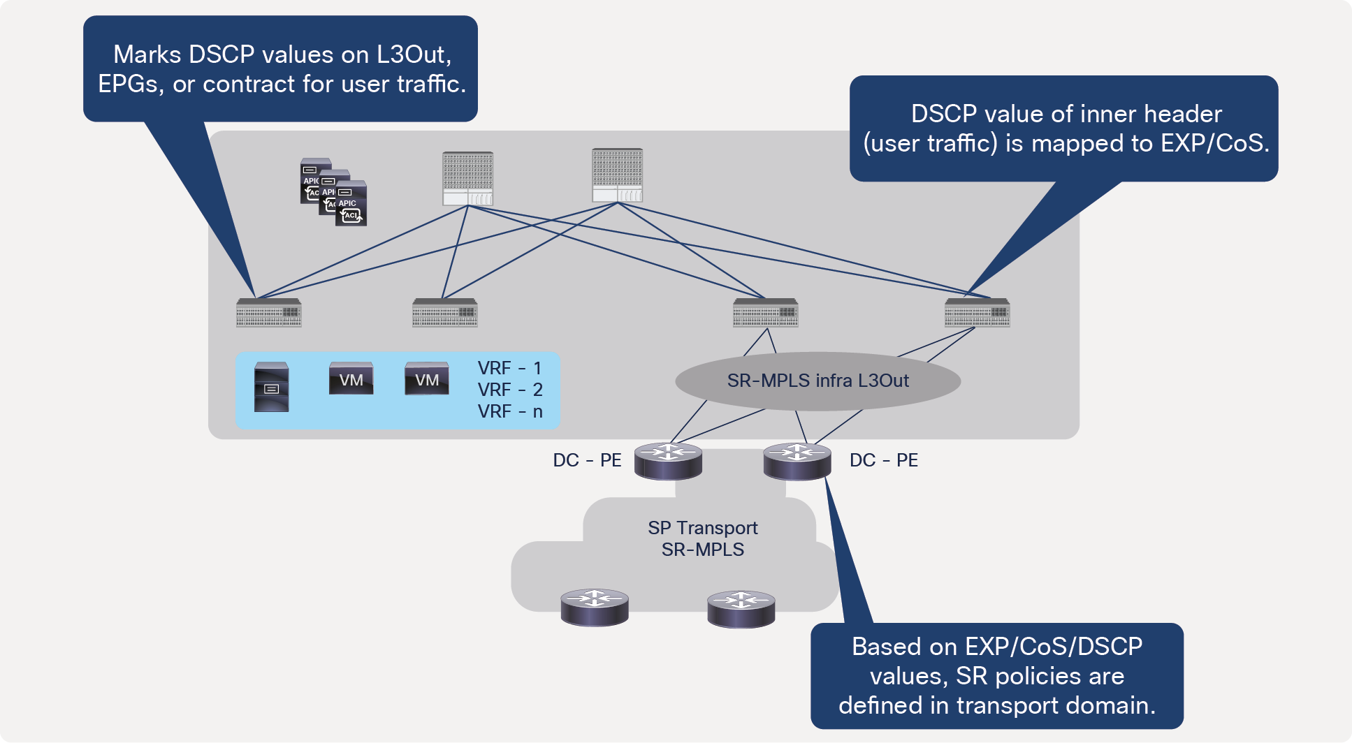
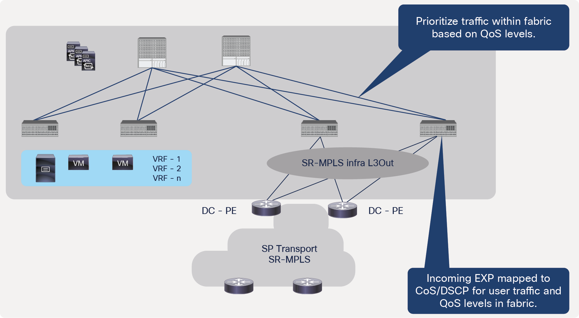
When the packet from the servers attached to the ACI fabric enter the fabric, the DSCP values for the packets can be marked using Quality-of-Service (QoS) policies defined at the ACI EPG, L3Out, and contract. By default, the ACI border leaf doesn’t modify the DSCP values of the packets; it marks outgoing MPLS packets with 0 EXP value, but, optionally, it can mark EXP bits with a different value-based DSCP of the user traffic using MPLS QoS policies defined on SR-MPLS infra L3Out. On the DC-PE, based on the DSCP values of the incoming packets, different SR policies can be defined to steer traffic differently in the transport domain. This behavior provides the automated policy translation between the datacenter and transport domains.
The ACI border leaf can also mark the Class-of-Service (CoS) bits based on the DSCP value of the user traffic while forwarding to the DC-PE. This can be useful when a sub-interface is being used between the ACI border leaf and the DC-PE, and the DC-PE is using CoS to define different SR policies in the transport domain. The border leaf forwards packets to the MPLS network with the original CoS value of the user traffic if the CoS preservation is enabled in the ACI fabric.
Figure 49 explains this behavior.
Egress SR-MPLS QoS from ACI border leaf
Similarly, when the traffic is coming from the DC-PE, the ACI border leaf can mark user traffic with DSCP/CoS values and change QoS levels within the fabric based on incoming EXP values in the traffic. QoS levels are used to prioritize the traffic within the ACI fabric. By default, ACI marks use QoS level 3 for the traffic. Figure 50 shows this behavior. The ACI border leaf retains the original DSCP values for user traffic coming from SR-MPLS without any re-marking while forwarding traffic within the fabric.
Ingress SR-MPLS QoS on ACI border leaf
Customers can apply per-interface policers on SR/MPLS interfaces depending on the use case. However, per-VRF policers are not supported as of this writing.
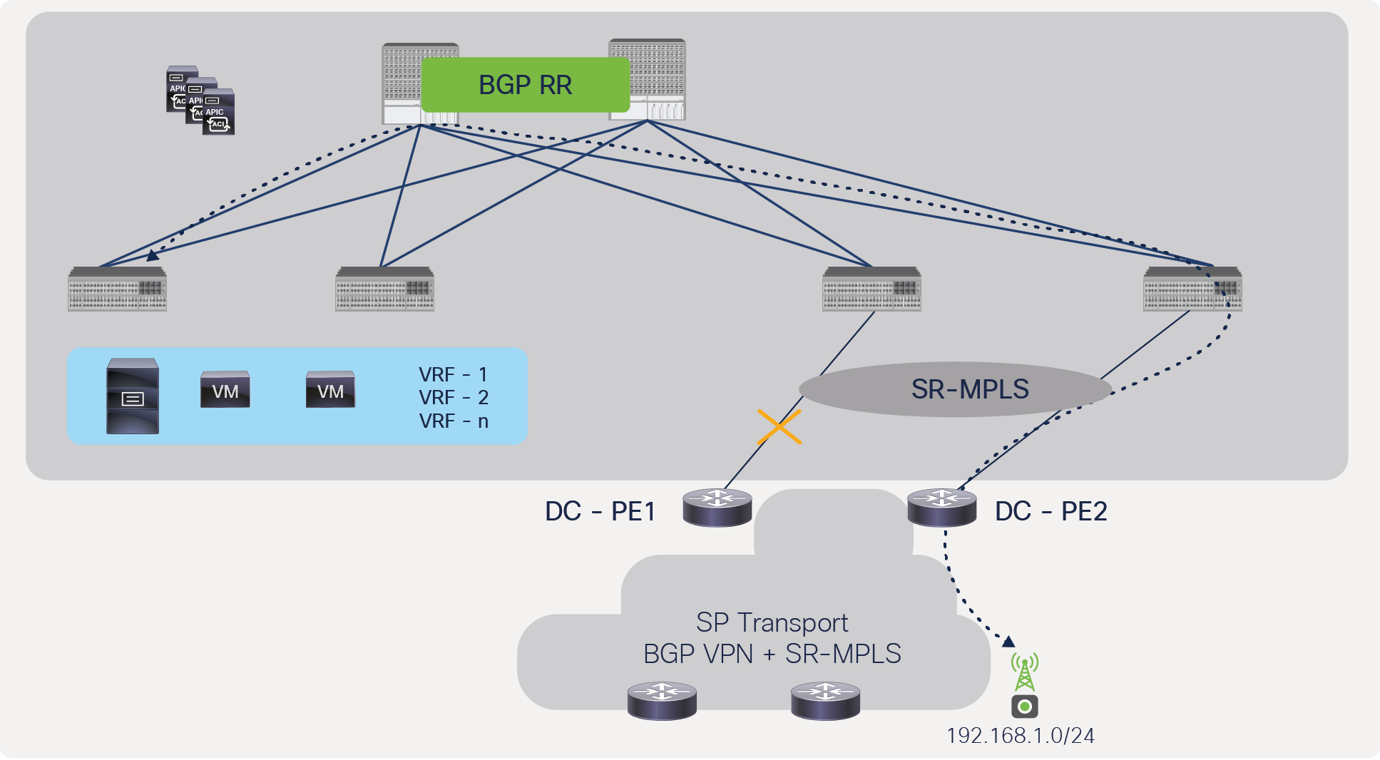
It is highly recommended to use full-mesh connectivity between the ACI border leaf and the DC-PE. It provides better redundancy and faster convergence. As shown in Figure 51, the ACI border leaf uses ECMP and forward traffic to both DC-PEs.
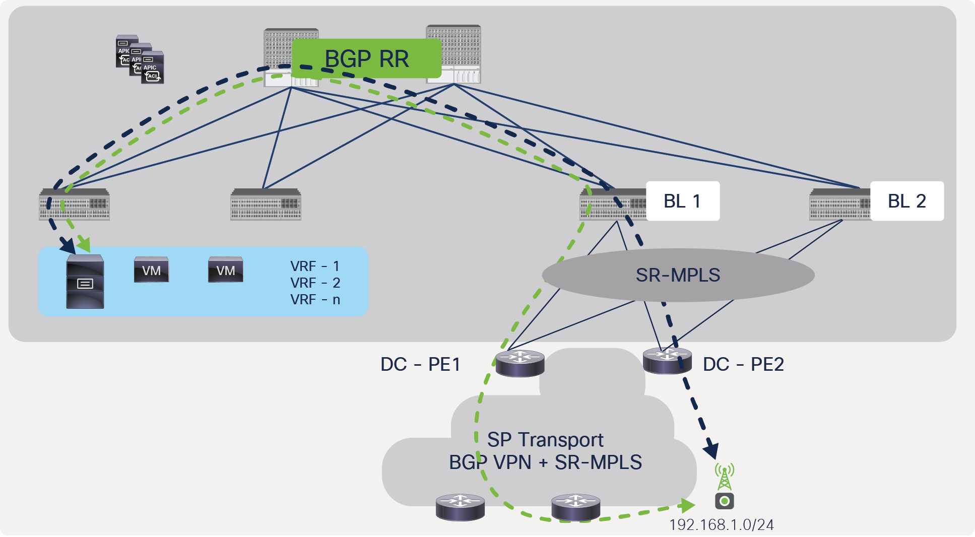
Redundancy between ACI border leafs and DC-PEs
When the link(s) to the DC-PE(s) fail on the border leaf, the border leaf uses the alternate DC-PE immediately since the border leaf still has connectivity through the alternate PE. In this case, the convergence time for application traffic is going to be minimal.
Traffic convergence due to failure of link between ACI border leaf and DC-PE, with full redundancy
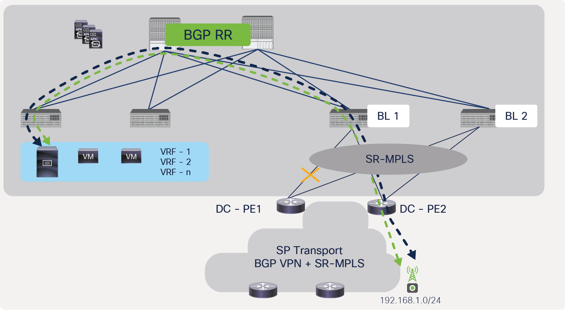
In a scenario where the ACI border leaf and the DC-PE don’t have full-mesh connectivity, if connectivity to a DC-PE is lost, then the border leaf needs to withdraw the prefix learned from the DC-PE and sends the withdraw message to the spine using BGP, as shown in Figure 53.
BGP withdraw message from ACI border to spine due to failure of link between ACI border leaf and DC-PE, without full redundancy (not recommended)
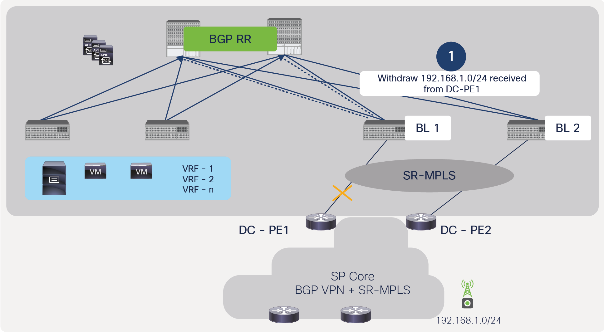
After receiving the withdraw message from the border leaf, the spine will send a withdraw message to all of the other leafs to remove the next-hop of the border leaf that lost connectivity to the DC-PE; this will avoid the “black holing” of traffic at the border leaf. This behavior is shown in Figure 54.
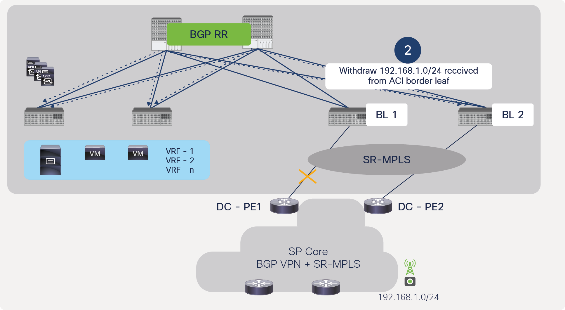
BGP withdraw message from spine to all ACI leafs to withdraw border leaf that lost connectivity to DC-PE (not recommended)
After all leaf nodes receive the withdraw message and remove the next-hop towards the failing border leaf TEP, the traffic can go through an alternate border leaf, but this process can take time and cause higher convergence. Figure 55 shows this behavior.
Traffic convergence due to failure of link between ACI border leaf and DC-PE, without full redundancy (not recommended)
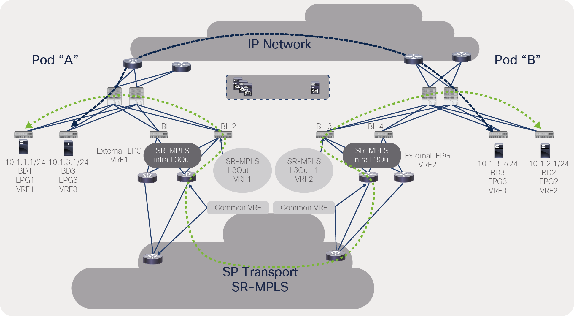
There are scenarios where the ACI fabric may transit between two SR/MPLS domains; in other words, the fabric is acting as a hub network for two SR/MPLS domains. This section will cover those scenarios and Cisco ACI’s support for them.
Figure 56 captures a scenario where the ACI fabric acts as a transit for same-VRF traffic. In this scenario, the user must configure two SR/MPLS infra L3Outs and make sure each SR/MPLS infra L3Out advertises a unique prefix. This scenario is supported if different border leaf pairs are used for transit traffic in the same VRF, as shown in Figure 56.
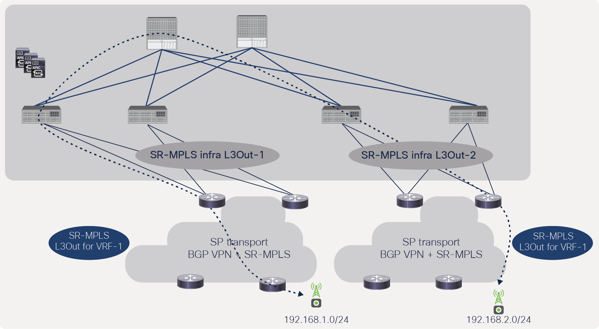
Transit traffic within the same VRF but through a different border-leaf pair
Figure 57 captures a scenario where the ACI fabric acts as a transit for different-VRF traffic, but within the same border leaf pair. This scenario is supported in Cisco ACI.
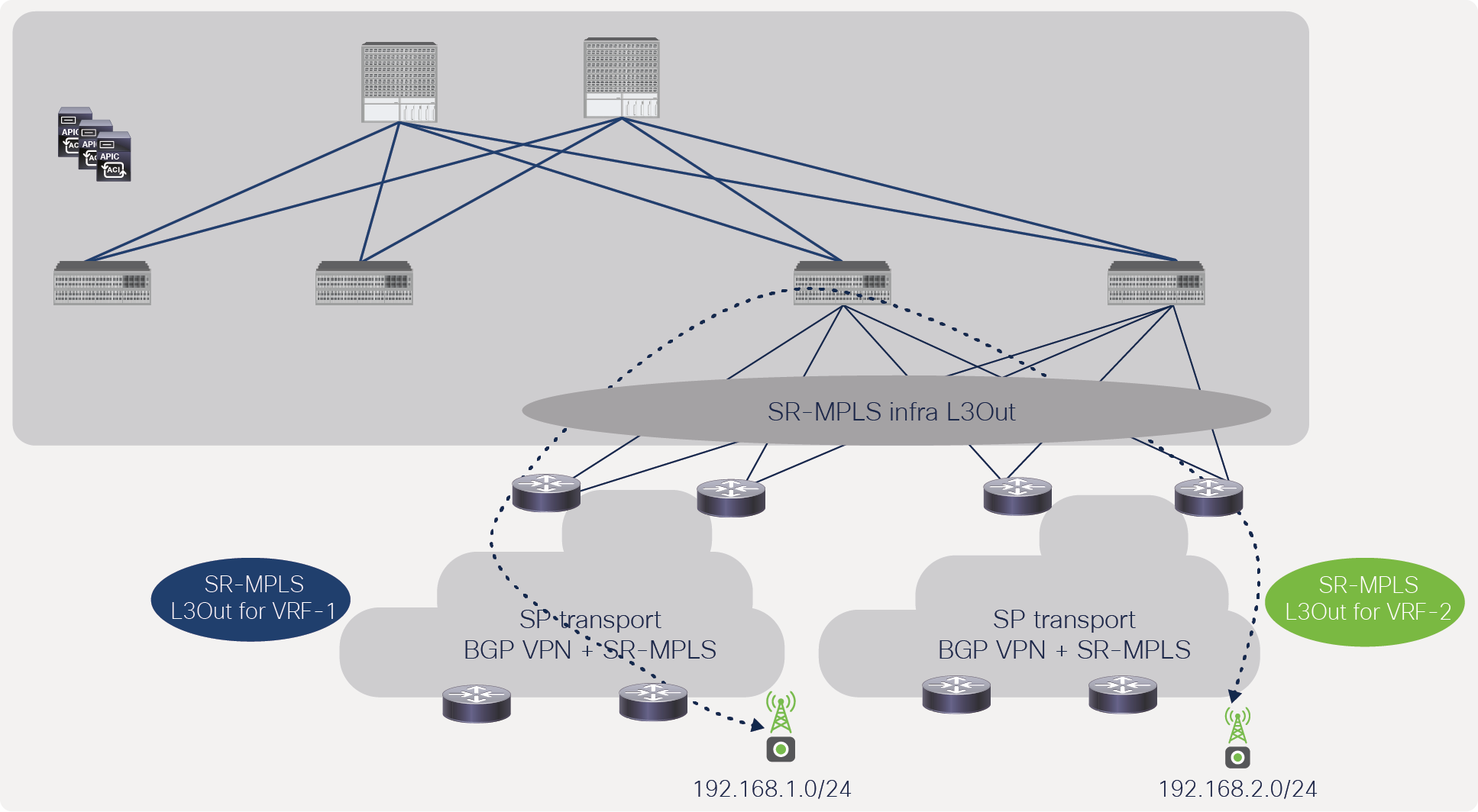
Transit traffic within same border-leaf pair but through different VRFs
Figure 58 captures a scenario where the ACI fabric acts as a transit for different VRFs traffic across a different border-leaf pair. This scenario is supported in Cisco ACI.
Transit traffic through a different border-leaf pair and different VRFs
Figure 59 captures a scenario where the ACI fabric acts as a transit for same-VRF traffic and within a border-leaf pair. This scenario is not supported in Cisco ACI as of this writing of this whitepaper in Cisco ACI Release 5.0(1).

Transit traffic within the same border leaf pair and VRF
Cisco APIC shows all VRF labels and stats on a single screen on SR-MPLS infra L3Out, as shown on the snapshot below.
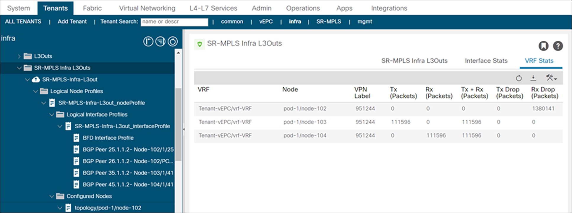
Snapshot of SR/MPLS packet stats of each VRF from APIC controller
SR/MPLS interface stats across all SR/MPLS-enabled interfaces can be seen from the APIC, as shown in snapshot below.
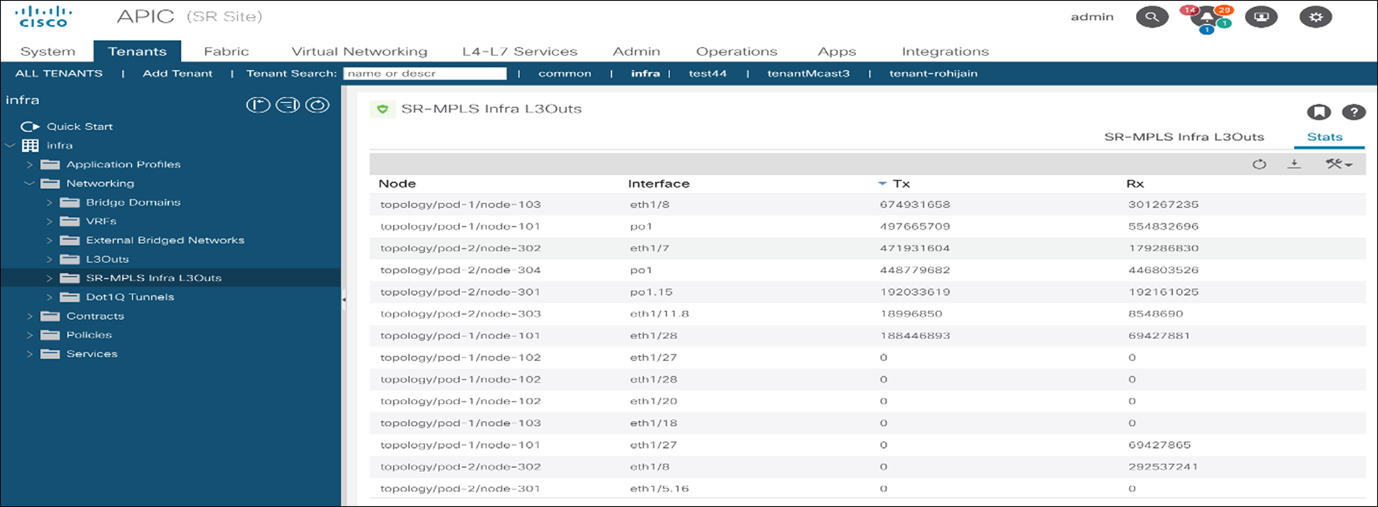
Snapshot of SR/MPLS packet stats on SR/MPLS enabled interfaces from APIC controller
SR-MPLS infra L3Out provides full visibility into BGP label unicast and BGP EVPN neighbors, as show in the snapshots below.
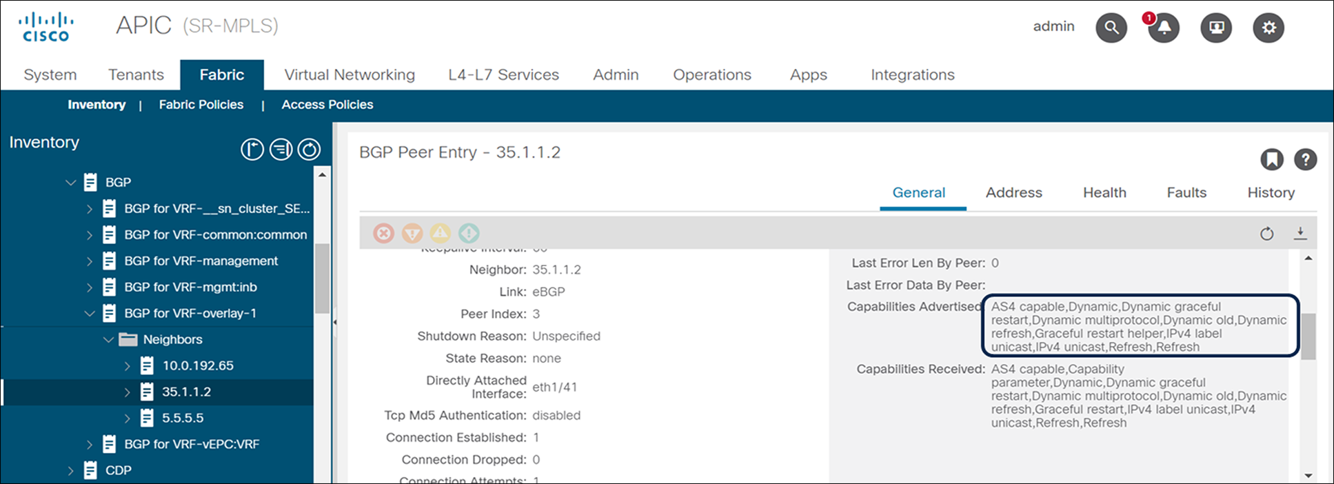
BGP Labeled unicast neighbor status
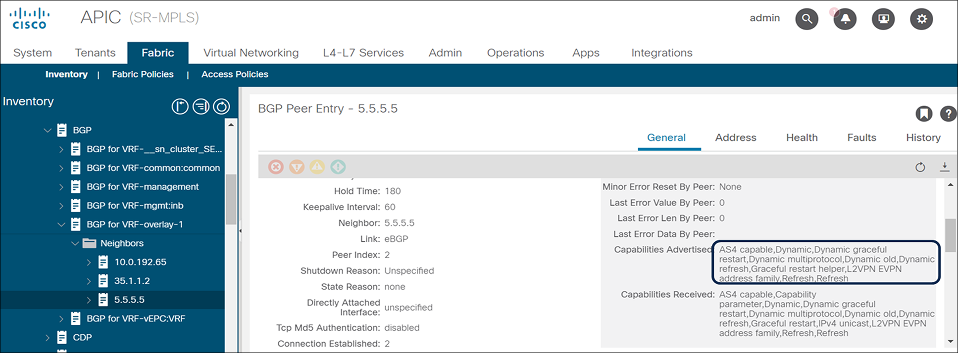
BGP EVPN neighbor status
Above are just a few examples of visibility and operations capability provided through APIC for SR/MPLS. Customers can fully operate, troubleshoot, and gain visibility into SR/MPLS, BGP LU, and BGP EVPN from APIC.
● Only eBGP is supported between ACI border leafs and DC-PEs.
● MPLS interface stats are not supported on -FX platforms.
● VRF-based QoS policing is not supported.
Please look at the ACI configuration guide for detailed guidelines and limitations. Below link has configuration guides for all ACI features and solution.
Customers can use Cisco Network Services Orchestrator (NSO) to define and orchestrate end-to-end service across the data-center and transport domains. As shown in Figure 64, NSO can push configuration to both transport and multiple data-center fabrics, including remote leafs, to bring up complete service. As of this writing, NSO Network Element Drivers (NED) for ACI and transport devices need to be used for provisioning the ACI fabric and IP/SR-MPLS handoffs from the data center to transport. However, there is a plan to build an NSO Core Function Pack (CFP) that will be purpose-built to support cross-domain orchestration use cases between the data center and transport for both IP and SR-MPLS handoffs.
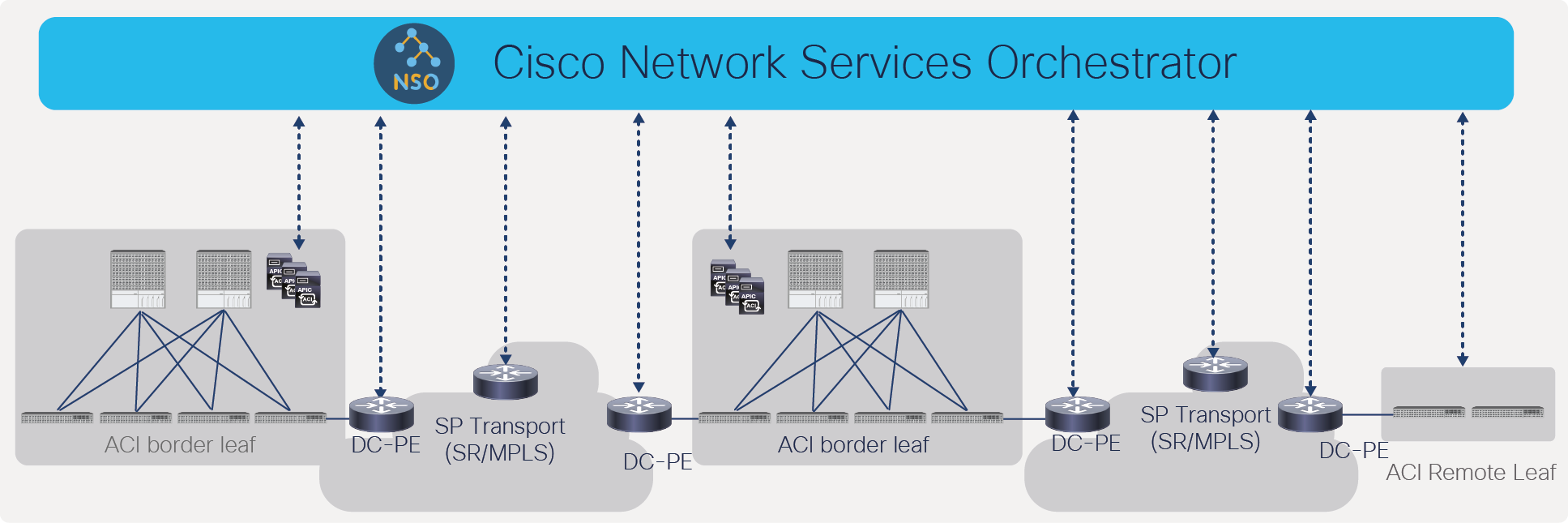
Cross-domain orchestration from Cisco Network Services Orchestrator
Figure 65 shows how NSO can be used for orchestrating 4G/5G services across the data center and transport.
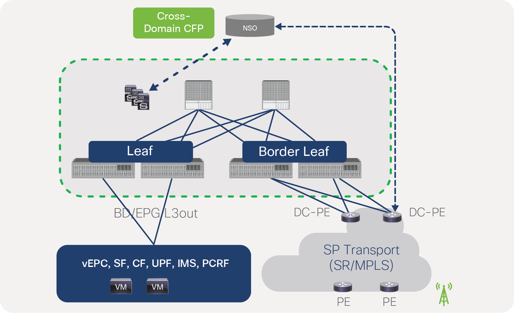
SR/MPLS configuration from NSO across the data center and transport
As shown in Figure 66, NSO can be used in the following SR-MPLS handoff use cases:
● Cross-domain service provisioning by configuring the following on the ACI border leaf and the DC-PE:
◦ VRF, RT, RD, VPN
◦ BFD
◦ BGP
◦ MPLS QoS policies
◦ BGP EVPN and labeled unicast session
◦ SR/MPLS QoS policies
● Route-Target (RT) translation from EVPN to L3VPN on the DC-PE since SP transport may be using BGP L3VPN instead of BGP EVPN
● Consistent policy across the data-center and transport domains by defining the BGP color community in the data center and defining SR policies based on the color community in the transport domain
● Consistent policy across the data-center and transport domains by defining DSCP/EXP policies in the data center, and use flow based on the demand next hop (ODN) feature of SR, based on the DSCP/EXP defined in the data center
In summary, Cisco ACI to SR/MPLS handoff allows customers to connect the data center to an edge router in a scalable and automated way by connecting multiple VRFs using a single BGP EVPN session instead of per-VRF routing protocol sessions. It also allows customers to use consistent policies across transport and the data center by setting the BGP color community in the EVPN prefix in the data center and using this community in the transport domain for defining SR policy. Since the transport network typically uses the SR/MPLS data plane, SR/MPLS handoff allows customers to use a unified data plane across the transport network.