Cisco 1 GHz GainStar Mini Node with 85/105 MHz Split Data Sheet
Available Languages
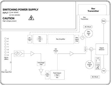
The Cisco® 1 GHz GainStar Mini Node (GSMN) is a compact node specifically designed to serve in fiber-deep hybrid fiber-coaxial (HFC) networks. The Cisco GSMN (Figure 1 and Figure 2) provides excellent forward and reverse path performance combined with high reliability and a user-friendly layout. All new Cisco GainStar products share common plug-in accessories and perform to 1 GHz in the forward path.
The Cisco 1 GHz GSMN uses GaAsFET technology optimized for superior distortion performance. It provides a single higher-level output or two lower-level RF output ports in a strand-mount configuration. In addition, it features onboard LEDs to indicate the optical input power. The integrated optical receiver module with a built-in AGC increases reliability and decreases nonlinear distortion. Reverse traffic can be combined and routed to an FP, DFB or CWDM reverse optical transmitter.
Features
● 1-GHz performance
● Selectable single or dual outputs with an onboard signal director
● LED display for optical input power
● AGC optical input range of -4 to 2 dBm
● Standard plug-in attenuators that are used to adjust the gain and equalization
● FP, DFB, or CWDM transmitter (available option)
● Surge-resistant circuitry that helps ensure resistance to high-voltage transients (6kV)
● Thermal RF control that reduces gain movement over temperature
● 10A current capacity (steady state) and 15A surge survivability
● Outdoor housing is IP68 dustproof and watertight
● PG11 or 5/8-inch ports with adapter included
● RoHS 6 of 6

Specifications
Tables 1 through 9 provide product specifications for the Cisco 1 GHz GainStar Mini Node with 85/105 MHz Split.
Table 1. Optical Section Specifications
| Feature |
Description |
| Forward Receiver Module |
|
| Wavelength |
1310 and 1550 nm |
| Optical AGC range |
-4 to 2 dBm |
| Optical AGC control stability |
±1.0 dB |
| Pass band |
50 to 1000 MHz |
| Frequency response1 |
±0.5 dB |
| Tilt (±1.0 dB) |
0 dB |
| Equivalent input noise |
≤ 8 pA/ |
| RF output level @ 0 dBm optical input2 |
Refer to chart below. |
|
|
|
| Notes: 1. For forward receiver module only. Does not include the frequency response contributions from forward optical transmitter. 2. Minimum receiver RF output level for the stated transmitter percent optical modulation index per channel (OMI/ch), with receiver optical input power of 0 dBm. |
|
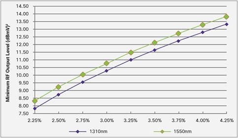
Table 2. Forward RF Section Specifications
| Feature |
Description |
|
| Forward RF |
||
| Frequency range |
105 to 1000 MHz |
|
| RF reference output level @... 1000 MHz 862 MHz 750 MHz 650 MHz 550 MHz 105 MHz |
1 port 50.0 dBmV 47.8 dBmV 46.1 dBmV 44.5 dBmV 42.9 dBmV 36.0 dBmV |
2 ports 46.5 dBmV 44.3 dBmV 42.6 dBmV 41.0 dBmV 39.4 dBmV 32.5 dBmV |
| Internal tilt1 |
14 ±1 dB |
|
| Gain2 |
39 dB, 1 port 35.5 dB, 2 ports |
|
| Frequency response |
±0.75 dB |
|
| Output return loss |
≥ 16 dB |
|
| RF output test point |
–20 ±1 dB, 1 port –16.5 ±1 dB, 2 ports |
|
| Hum |
65 dB @10 A |
|
| Noise figure2 |
< 7 dB |
|
| Distortion @ 73 NTSC + digital3, 4, 5 CTB CSO XMOD |
68 dB 63 dB 60 dB |
|
| Distortion @ 58 PAL B/G + digital3, 4, 5 CTB CSO |
74 dB 73 dB |
|
| Distortion @ 42 cenelec3, 4 CTB ≥ 66 dB CSO ≥ 60 dB |
112 dBµV 111 dBµV |
|
| Notes: Unless otherwise noted, specifications reflect typical performance and are referenced to 20ºC. 1. Forward internal tilt specified is primarily due to an on-board equalizer 7 dB (1 GHz band) and a factory configured 7 dB (1GHz band) linear output equalizer. 2. Noise figure measured with 0 dB input EQ and 0 dB input pad. 3. With 3 dB interstage Pad installed for 1 GHz. 4. Tilt 14 dB 5. Distortion performance reference output level is 50 dBmV (1 port). Digital refers to 550 MHz to 1 GHz loading with QAM carriers at -6 dB relative to analog CW carrier levels. |
||
Table 3. Reverse RF Section Specifications
| Feature |
Description |
| Reverse RF |
|
| Frequency range |
5 to 85 MHz |
| Frequency response |
±0.75 dB |
| Gain1 |
20 dB, 1 port 16.5 dB, 2 ports |
| Hum |
65 dB @ 10 A |
| Input return loss |
≥ 16 dB |
| Test point |
–20 ±1 dB, 1 port –23.5 ±1 dB, 2 ports |
| Noise figure1 |
< 9 dB |
| Notes: Unless otherwise noted, specifications reflect typical performance and are referenced to 20ºC. 1. Reverse Gain and Noise Figure measured with 0 dB EQ, 0 dB input pad, and 0 dB output pad. |
|
Table 4. Reverse Transmitter Module Specifications
| Feature |
FP Laser |
DFB Laser |
CWDM Laser |
| Wavelength |
1310 nm |
1310 nm |
1470 nm, 1490 nm, 1510 nm, 1530 nm, 1550 nm, 1570 nm, 1590 nm, 1610 nm |
| Pass band |
5 to100 MHz |
5 to100 MHz |
5 to 200 MHz |
| Frequency response1 |
±0.5 dB |
±0.5 dB |
±0.5 dB |
| Input return loss |
≥ 16 dB |
≥ 16 dB |
≥ 16 dB |
| Output optical power |
2.0 dBm |
3.0 dBm |
3.0 dBm |
| NPR2 |
15 dB @ 30 dB |
20 dB @ 30 dB |
25 @ 30 dB |
| RF test point |
-20 dB |
-20 dB |
–203 |
| Notes: 1. Frequency response for transmitter module only: Does not include the frequency response contribution of an optical receiver. 2. NPR test condition: 7 dB optic link (15 km fiber, plus passive loss) 3. 10% OMI when 20 dBmV is detected |
|||
Table 5. Station Delay Characteristics
| Station Delay Characteristics |
|||
| Forward |
Reverse |
||
| Frequency (MHz) |
Delay (ns) |
Frequency (MHz) |
Delay (ns) |
| 109.25 to 112.83 |
8 |
5.0 to 6.5 |
35 |
| 115.25 to 118.83 |
5 |
6.5 to 8.0 |
15 |
| 121.25 to 124.83 |
3 |
8.0 to 9.5 |
8 |
| 80.5 to 82.0 |
9 |
||
| 82.0 to 83.5 |
13 |
||
| 83.5 to 85.0 |
15 |
||
Table 6. Electrical Specifications
| Feature |
Description |
| Electrical |
|
| Maximum AC through current (continuous) |
10A |
| Maximum AC through current (surge) |
15A |
Table 7. Station Powering Data (40-90 V)
| Station Powering Data |
|||||||||||||
| I DC * |
AC Voltage |
||||||||||||
| 90 |
85 |
80 |
75 |
70 |
65 |
60 |
55 |
50 |
45 |
40 |
|||
| 1 RX and 1 TX |
0.82 |
AC current (A) |
0.30 |
0.31 |
0.33 |
0.34 |
0.36 |
0.38 |
0.42 |
0.43 |
0.47 |
0.52 |
0.58 |
| Power (W) |
16.0 |
16.0 |
15.9 |
15.9 |
15.9 |
15.9 |
15.9 |
16.0 |
16.0 |
16.1 |
16.3 |
||
| * Data is based on stations configured for two-way operation. AC currents specified are based on measurements made with typical CATV type ferroresonant AC power supply (quasi-square wave), |
|||||||||||||
Table 8. Station Powering Data (100 to 240V)
| Station Powering Data |
|||||||||||||||||
| I DC * |
AC Voltage |
||||||||||||||||
| 240 |
230 |
220 |
210 |
200 |
190 |
180 |
170 |
160 |
150 |
140 |
130 |
120 |
110 |
100 |
|||
| 1 RX and 1 TX |
0.82 |
AC current (A) |
0.14 |
0.15 |
0.15 |
0.16 |
0.16 |
0.17 |
0.17 |
0.18 |
0.19 |
0.12 |
0.21 |
0.22 |
0.23 |
0.25 |
0.26 |
| Power (W) |
16.3 |
16.3 |
16.3 |
16.2 |
16.1 |
16.0 |
16.0 |
16.0 |
15.9 |
15.8 |
15.8 |
15.8 |
15.7 |
15.7 |
15.7 |
||
| * Data is based on stations configured for 2-way operation. AC currents specified are based on measurements made with typical CATV type ferroresonant AC power supply (quasi-square wave). |
|||||||||||||||||
Table 9. Mechanical and Environmental Specifications
| Feature |
Description |
| Mechanical |
|
| Water and dust ingress rating |
IP68 |
| Dimensions (H x W x D) |
90 x 234 x 212 mm 3.5 x 9.2 x 8.4 in. |
| Weight |
3.0 kg 6.6 lb |
| Environmental |
|
| Operating temperature |
-40 to 60°C -40 to 140°F |
| Storage temperature |
-40 to 85°C -40 to 185°F |
| Compliance |
EU RoHS 6/6, IEC/EN 60728-11, IEC/EN 60065, EN60825-1:2007, EN 50083-2, FCC Part 76, Subpark K, CB Scheme Certification with all national deviations and CENELEC Common Mods |
Ordering Information
To place an order, visit the Cisco Ordering Home Page and refer to the ordering information provided in Tables 10 through 12.
Table 10. Ordering Information
| Product Description |
Part Number |
| Cisco 1 GHz GainStar Mini Node, 85/105MHz Split, Strand, Rev DFB Tx, Rev/20, SC/APC, 60V |
S311G83001012020 |
| Cisco 1 GHz GainStar Mini Node, 85/105MHz Split, Strand, Rev DFB Tx, Rev/20, SC/APC, 220V, India Cord |
S311G83002512020 |
| Cisco 1 GHz GainStar Mini Node, 85/105MHz Split, Strand, Rev FP Tx, Rev/20, SC/APC, 60V |
S311G83001012010 |
Table 11. Required Accessories
| Required Accessories for RF Module |
Part Number |
| Plug-in Pads (attenuators) - Available in 1 dB steps from 0 to 20 dB
●
1 required for reverse input
●
1 required for reverse output
|
4036021 (0 dB) sequentially through 4036041 (20 dB) |
Table 12. Optional Accessories
| Part Number |
|
| Optical Transmitter |
|
| Cisco GainStar 1310 nm FP Optical Transmitter 2 dBm, with SC/APC |
4034446 |
| Cisco GainStar 1310 nm FP Optical Transmitter 2 dBm, with FC/APC |
4034448 |
| Cisco GainStar 1310 nm DFB Optical Transmitter 3 dBm, with SC/APC |
4034447 |
| Cisco GainStar 1310 nm DFB Optical Transmitter 3 dBm, with FC/APC |
4034449 |
| Cisco GainStar 1470 nm CWDM Optical Transmitter 3 dBm, with SC/APC |
4039243 |
| Cisco GainStar 1490 nm CWDM Optical Transmitter 3 dBm, with SC/APC |
4039244 |
| Cisco GainStar 1510 nm CWDM Optical Transmitter 3 dBm, with SC/APC |
4039245 |
| Cisco GainStar 1530 nm CWDM Optical Transmitter 3 dBm, with SC/APC |
4039246 |
| Cisco GainStar 1550 nm CWDM Optical Transmitter 3 dBm, with SC/APC |
4039247 |
| Cisco GainStar 1570 nm CWDM Optical Transmitter 3 dBm, with SC/APC |
4039248 |
| Cisco GainStar 1590 nm CWDM Optical Transmitter 3 dBm, with SC/APC |
4039249 |
| Cisco GainStar 1610 nm CWDM Optical Transmitter 3 dBm, with SC/APC |
4039250 |
| Reverse Amplifier Module |
|
| Cisco GainStar Reverse Amplifier Module, 20dB Gain (5-85 MHz) |
GS-REV-AMP-20-85 |
| Reverse Equalizer |
|
| Plug-in Reverse Equalizer: Available from 0 to 10 dB 0 to 5 dB EQ (GS-REQ-85-00-05) and 0 dB Pad (4036021) are provided - Other values must be ordered.
●
1 required for reverse input; 1 Pad also required and plugged into EQ
85 MHz platform:
◦ Cisco GainStar Reverse Cable Equalizer 0 to 5 dB ◦ Cisco GainStar Reverse Cable Equalizer 6 to 10 dB |
GS-REQ-85-00-05 GS-REQ-85-06-10 |
| Forward Equalizer |
|
| Plug-in Forward Equalizer: Available from 0 to 14 dB 5 to 9 dB EQ (4034460) and 7 dB Pad - Other values must be ordered.
●
1000 MHz platform:
◦ GainStar Forward Linear Equalizer 0 to 4 dB ◦ GainStar Forward Linear Equalizer 5 to 9 dB ◦ GainStar Forward Linear Equalizer 10 to 14 dB |
4034459 4034460 4034461 |
| Directional Coupler |
|
| Cisco GainStar 1GHz 8dB Directional Coupler |
GS-1G-DC-08 |
| Cisco GainStar 1GHz 12dB Directional Coupler |
GS-1G-DC-12 |
| Related Equipment |
|
| Cisco Plug-in 75 ohm Pad |
4036140 |
For More Information
Cisco 1 GHz GainStar Line Extender products offer the industry’s most complete range of high-performance components. For additional information, please go to:
http://www.cisco.com/c/en/us/products/video/gainstar-nodes/index.html
 Feedback