Cisco IP Fabric for Media Design Guide
Available Languages
Bias-Free Language
The documentation set for this product strives to use bias-free language. For the purposes of this documentation set, bias-free is defined as language that does not imply discrimination based on age, disability, gender, racial identity, ethnic identity, sexual orientation, socioeconomic status, and intersectionality. Exceptions may be present in the documentation due to language that is hardcoded in the user interfaces of the product software, language used based on RFP documentation, or language that is used by a referenced third-party product. Learn more about how Cisco is using Inclusive Language.
- US/Canada 800-553-2447
- Worldwide Support Phone Numbers
- All Tools
 Feedback
 Feedback
The documentation set for this product strives to use bias-free language. For the purposes of this documentation set, bias-free is defined as language that does not imply discrimination based on age, disability, gender, racial identity, ethnic identity, sexual orientation, socioeconomic status, and intersectionality. Exceptions may be present in the documentation due to language that is hardcoded in the user interfaces of the product software, language used based on RFP documentation, or language that is used by a referenced third-party product. Learn more about how Cisco is using Inclusive Language.
Prerequisites
This document assumes the reader is familiar with the functioning of a broadcast production facility and the IP transformation happening in the media and broadcasting industry, where production and other use cases leveraging Serial Digital Interface (SDI) infrastructure are moving to an IP infrastructure. The reader should be familiar with Society of Motion Picture and Television Engineers (SMPTE) 2022-6, 2110 standards and have a basic understanding of Precision Time Protocol (PTP). As per 2110 or 2022-6 specifications, the traffic on the IP fabric is User Datagram Protocol (UDP) multicast; hence, the reader should have a good understanding of IP unicast and multicast routing and switching.
This document is applicable to Cisco® NX-OS Software Release 9.3 and Cisco Nexus Dashboard Fabric Controller 12.0 and newer.
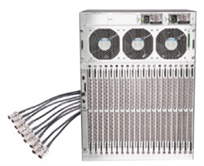
Today, the broadcast industry uses an SDI router and SDI cables to transport video and audio signals. The SDI cables can carry only a single unidirectional signal. As a result, many cables, frequently stretched over long distances, are required, making it difficult and time-consuming to expand or change an SDI-based infrastructure.
Cisco IP Fabric for Media helps you migrate from an SDI router to an IP-based infrastructure (Figures 1 and 2). In an IP-based infrastructure, a single cable has the capacity to carry multiple bidirectional traffic flows and can support different flow sizes without requiring changes to the physical infrastructure.
An IP-based infrastructure with Cisco Nexus® 9000 Series Switches supports:
● Various types and sizes of broadcasting equipment endpoints with port speeds up to 400 Gbps
● Transport of the latest video technologies, including 4K and 8K Ultra HD
● A deterministic network without packet loss. Furthermore, low latency, and minimal jitter, for multicast IP transport of live broadcast signals.
● AES67 and SMPTE-2059-2 PTP profiles for PTP time synchronization.
SDI router
IP fabric
The Society of Motion Picture and Television Engineers (SMPTE) 2022-6 standard defines the way that SDI is encapsulated in an IP frame. SMPTE 2110 defines how video, audio, and ancillary data are carried over IP. Similarly, Audio Engineering Society (AES) 67 defines the way that audio is carried over IP. All these flows are typically User Datagram Protocol (UDP) and IP multicast flows. A network built to carry these flows must provide zero-drop transport with forwarding, low latency, and minimal jitter.
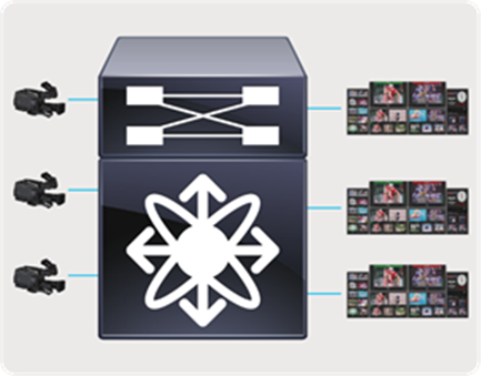
In a broadcast production facility, endpoints include cameras, microphone, multi-viewer, switchers, servers (playout), etc. Endpoints have either an SDI interface or an IP interface. Endpoints with an IP interface can be connected directly to a network switch. However, for endpoints that have an SDI interface, an IP Gateway (IPG) is needed to convert SDI to IP (2110/2022-6) and vice versa. In the latter case, the IP gateway is connected to the network switch with the endpoints connected to the IP gateway (Figure 3).
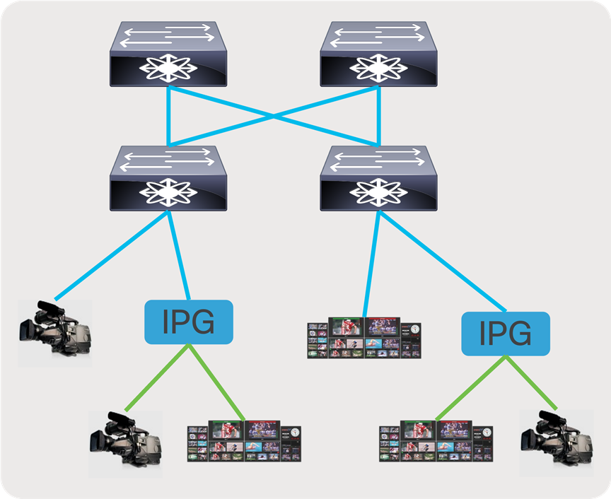
IP endpoints and gateways
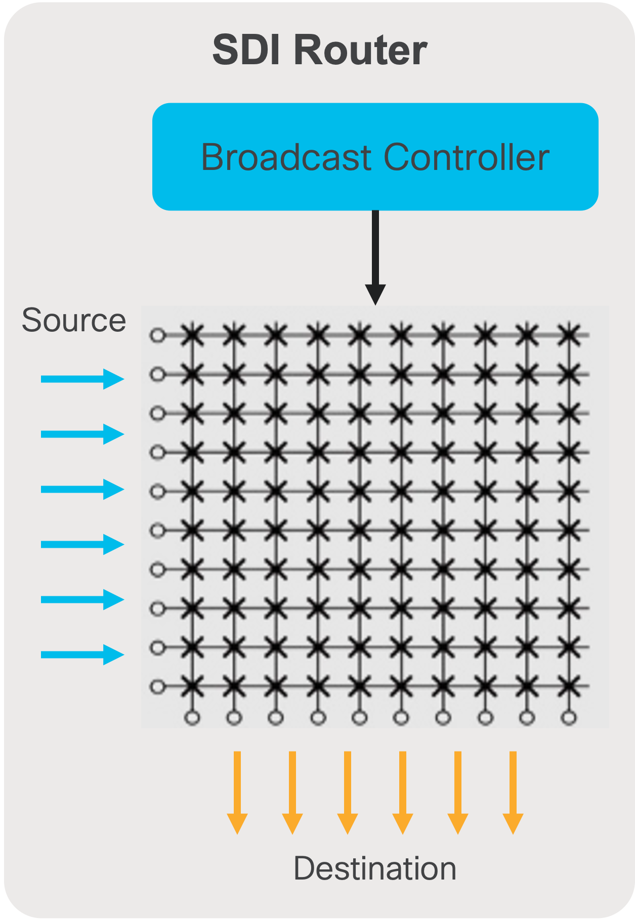
In an SDI environment, the broadcast controller managed the cross points of the SDI router (Figure 4). When an operator triggers a ‘take’, the destination switches from source A to source B using a control panel. The panel communicates with the broadcast controller, signaling the intent to make the switch. The broadcast controller reprograms the cross points on the SDI router to switch the destination from source A to source B.
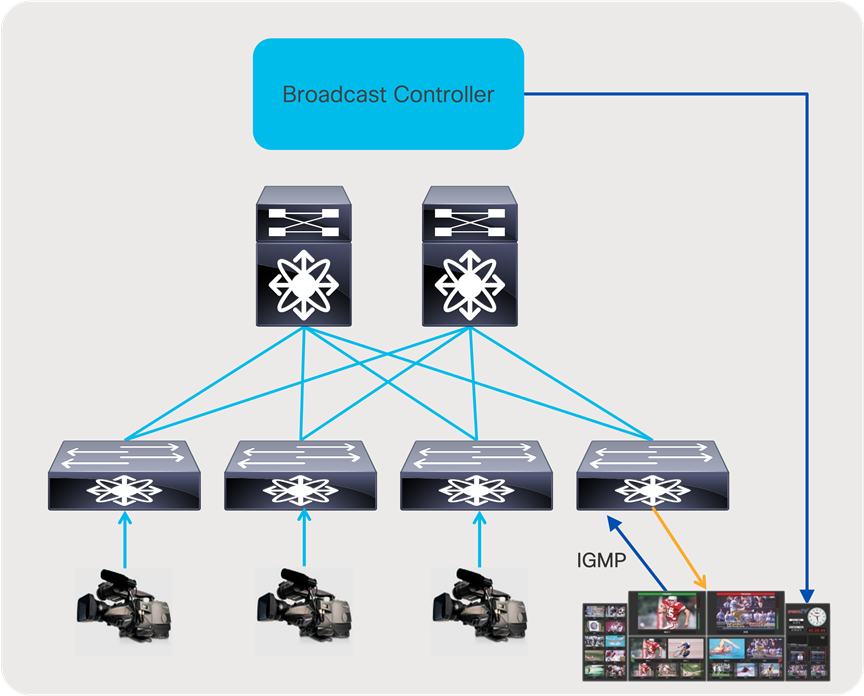
With an IP infrastructure, there are several options on how the broadcast controller integrates with the network. In most common deployments, when an operator triggers a ‘take’ on a control panel, the panel communicates with the broadcast controller, signaling the intent to switch. The broadcast controller then communicates directly with the IP endpoint or IP gateway to trigger an Internet Group Management Protocol (IGMP) leave and join toward the IP network. The network then delivers the new flow to the destination and removes the old. This type of switching is called destination timed switching (Figure 5).
In some deployments, the broadcast controller that uses APIs exposed by the network/network controller can instruct the network to switch a destination from source A to source B without involving the destination triggering an IGMP join as a signaling mechanism. The Advanced Media Workflow (AMWA) group defines IS-04, IS-05, and IS-06 specifications that describe how a broadcast controller, endpoints, and network/network controller communicate with one another to accomplish broadcast workflows in an IP environment.
Broadcast controller in an SDI environment
Broadcast controller in an IP environment
Cisco Nexus 9000 for IP Fabric for Media
Nexus 9000 Series Switches deliver proven high performance and density, low latency, and exceptional power efficiency in a range of form factors. The series also performs line-rate multicast replication with minimal jitter. Each switch can operate as a Precision Time Protocol (PTP) boundary clock and can support the SMPTE 2059-2 and AES67 profiles.
The following are the Cisco Nexus 9000 models supporting Cisco IP Fabric for Media, refer to release notes on software release version supporting the platforms:
● Nexus 9300-FX3
● Nexus 9300-FX2
● Nexus 9300-GX
● Nexus 9300-GX2A
● Nexus 9300-GX2B
● Nexus 9300-H2R
● Nexus 9300-H1
● Nexus 9300-FX
● Nexus 9300-FXP
● Nexus 9300-EX
● Nexus 9364C and 9332C
● Nexus 9200 (Excludes Nexus 9232E-B1)
● Nexus 9400
● Nexus 9500 chassis with N9K-X9636C-R and RX line cards
● Nexus 9500 chassis with N9K-X9636Q-R line card
● Nexus 9500 chassis with N9K-X9624D-R2 line card
● Nexus 9800 chassis with N9K-X9836DM-A and N9K-X98900CD-A line card
There are multiple design options available to deploy an IP Fabric for Media based on the use case.
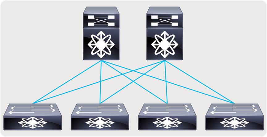
● A flexible and scalable layer 3 spine and leaf network - provides a flexible and scalable architecture that is suitable for studio deployments (Figures 6 and 7).
● A single switch with all endpoints and IPGs connected to this switch – provides the simplicity needed in an outside broadcasting TV van (OBVAN) and small studio deployment (Figure 8).
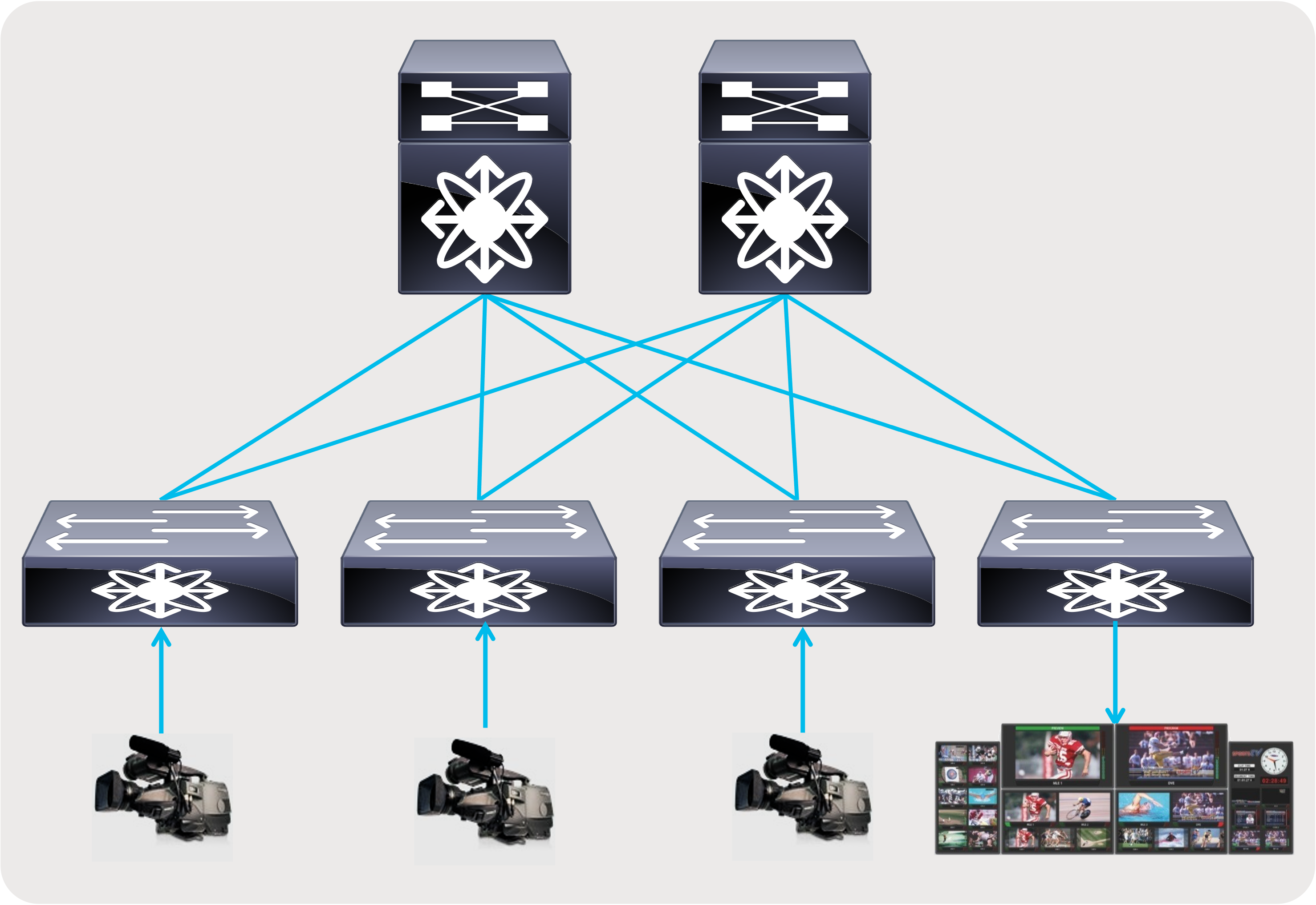
Spine and leaf with endpoints and IPGs connected to the leaf
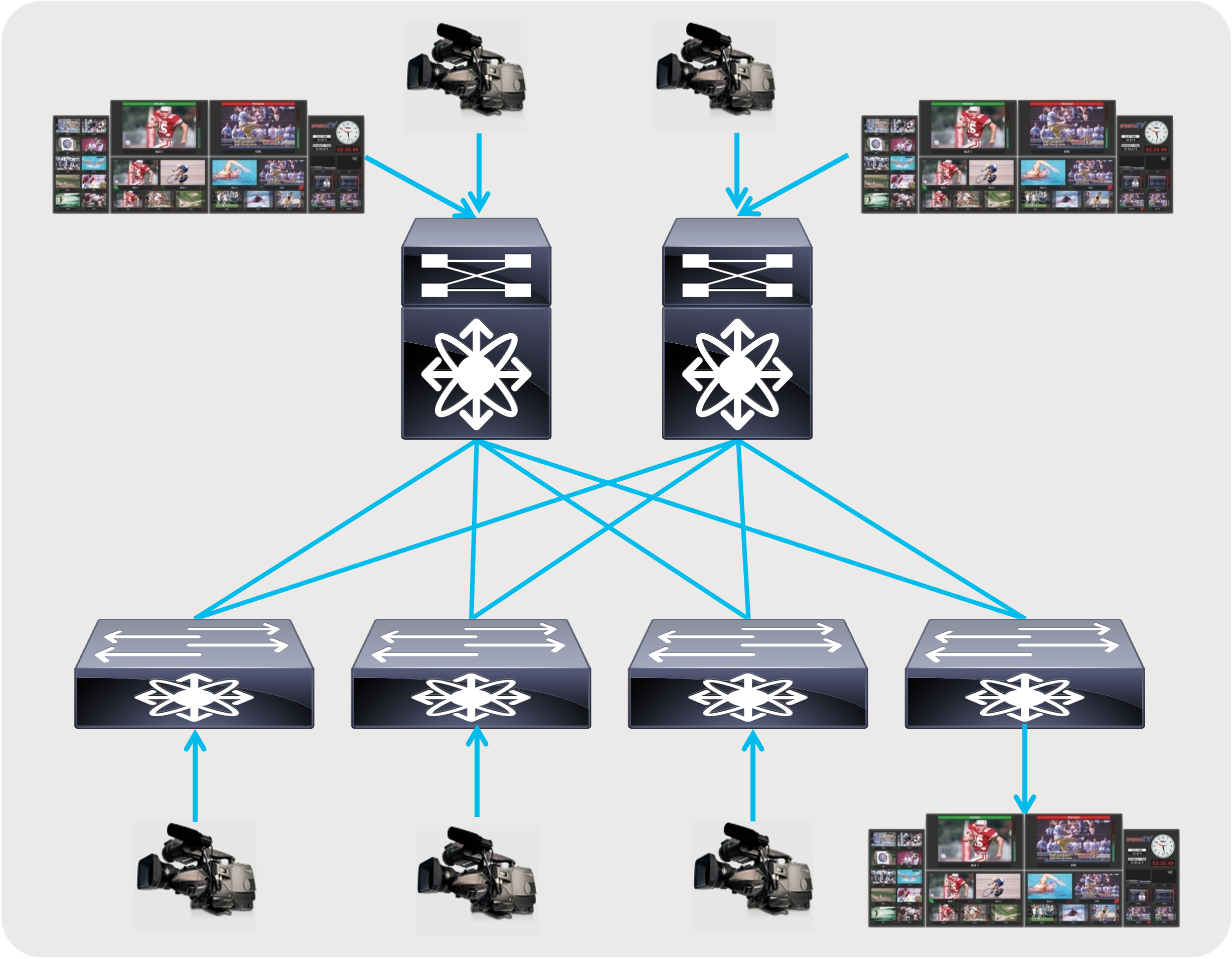
Spine and leaf with endpoints and IPGs connected to both spine and leaf
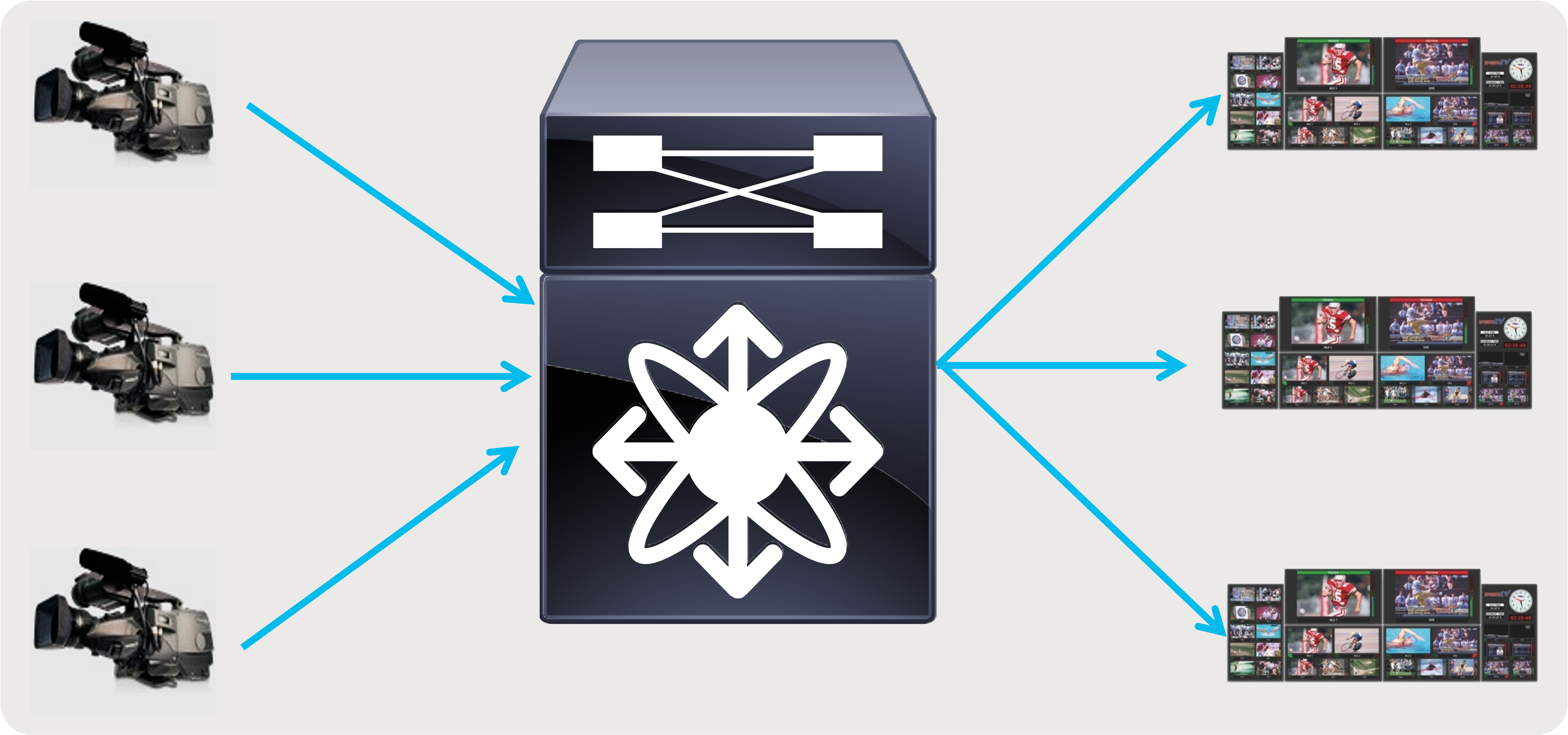
Single switch with endpoints and IPGs connected to the switch
Why use a Layer 3 Spine and Leaf Design
Spine and leaf CLOS architecture has proven to be flexible and scalable and is widely deployed in modern data center designs. No matter where the receiver is connected, the path always involves a single hop through the spine, thereby providing deterministic latency.
Although a layer 2 network design may seem simple, it has a very large failure domain. A misbehaving endpoint could potentially storm the network with traffic that is propagated to all devices in the layer 2 domain. Also, in a layer 2 network, traffic is always flooded to the multicast router or querier, which can cause excessive traffic to be sent to the router or querier, even when there are no active receivers. This results in non-optimal and non-deterministic use of bandwidth.
Layer 3 multicast networks contain the fault domain and forward traffic across the network only when there are active receivers, thereby promoting optimal use of bandwidth. This also provides granular application of filtering policy that can be applied to a specific port instead of all devices, like in case of a layer 2 domain.
Building Blocks of a Layer 3 IP Fabric
A specific set of IP protocols is needed to enable the network to carry media flows. As most media flows are UDP multicast flows, the fabric must be configured with protocols that transport multicast (Figure 9). The protocols needed to route traffic in the network is a subset of the following:
● Protocol Independent Multicast (PIM) - PIM enables routing multicast between networks.
● Interior Gateway Protocol (IGP) - IGP, like Open Shortest Path First (OSPF), enables unicast routing in the IP fabric. PIM relies on the unicast routing information provided by the IGP to determine the path to the source.
● Internet Group Management Protocol (IGMP) - IGMP is a protocol in which the destination (receiver) signals the intent to join a source or leave a source.
● Multicast Source Discovery Protocol (MSDP) - MSDP is required for Rendezvous Point (RP) to sync the source information when running any source multicast (ASM with IGMPv2).
Along with these protocols, the network must be configured with Quality of Service (QoS) to provide better treatment of media flows (multicast) over file-based flows (unicast).
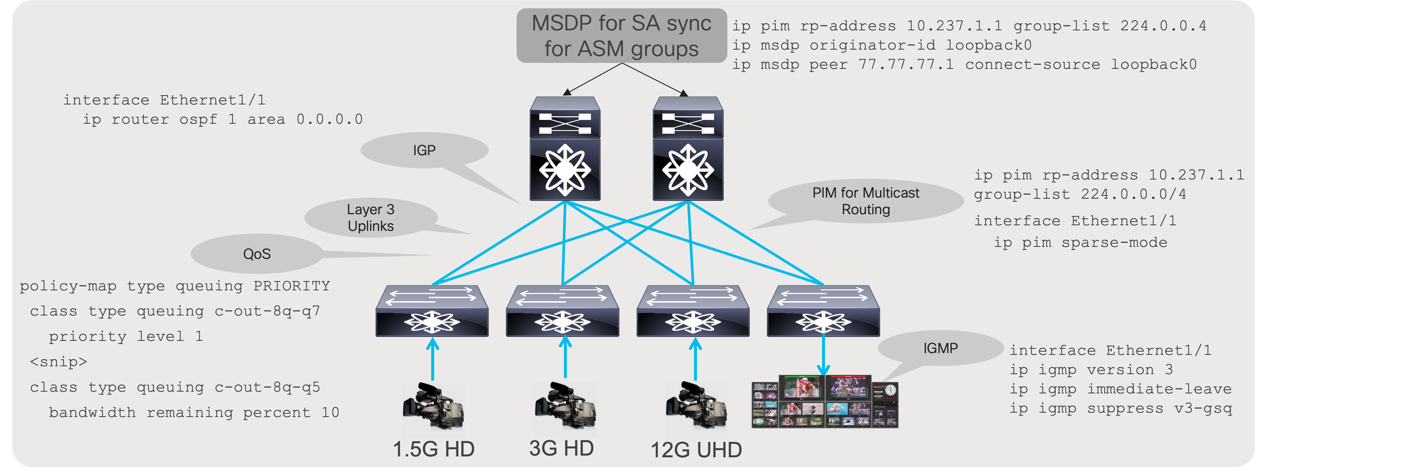
Building blocks of a media fabric
Cisco Non-Blocking Multicast (NBM)
In an IP network, multiple paths exist between the source and destination, for every request to switch or create a new flow being made by the operator The protocols setting up the flow path (PIM) chooses one of available paths using a hash. The hash does not consider bandwidth, which may not always result in equal distribution of load across available paths.
In IT data centers, Equal-Cost Multipath (ECMP) is extremely efficient because most traffic is Transmission Control Protocol (TCP)-based, with millions of flows and the load distribution more likely to be uniform across all available paths. However, in a media data center that typically carries uncompressed video along with audio and ancillary flows, Equal-Cost Multipath (ECMP) routing may not always be as efficient, because of the lower number of flows. In that case there is a possibility that all video flows hash along the same path, oversubscribing the path.
PIM is extremely efficient and very mature; it lacks the ability to use bandwidth as a parameter when setting up a flow path. Cisco developed the Non-Blocking Multicast (NBM) process on NX-OS that makes PIM intelligent. NBM brings bandwidth awareness to PIM. NBM and PIM can work together to provide an intelligent and efficient network that prevents oversubscription and provides bandwidth availability for multicast delivery.
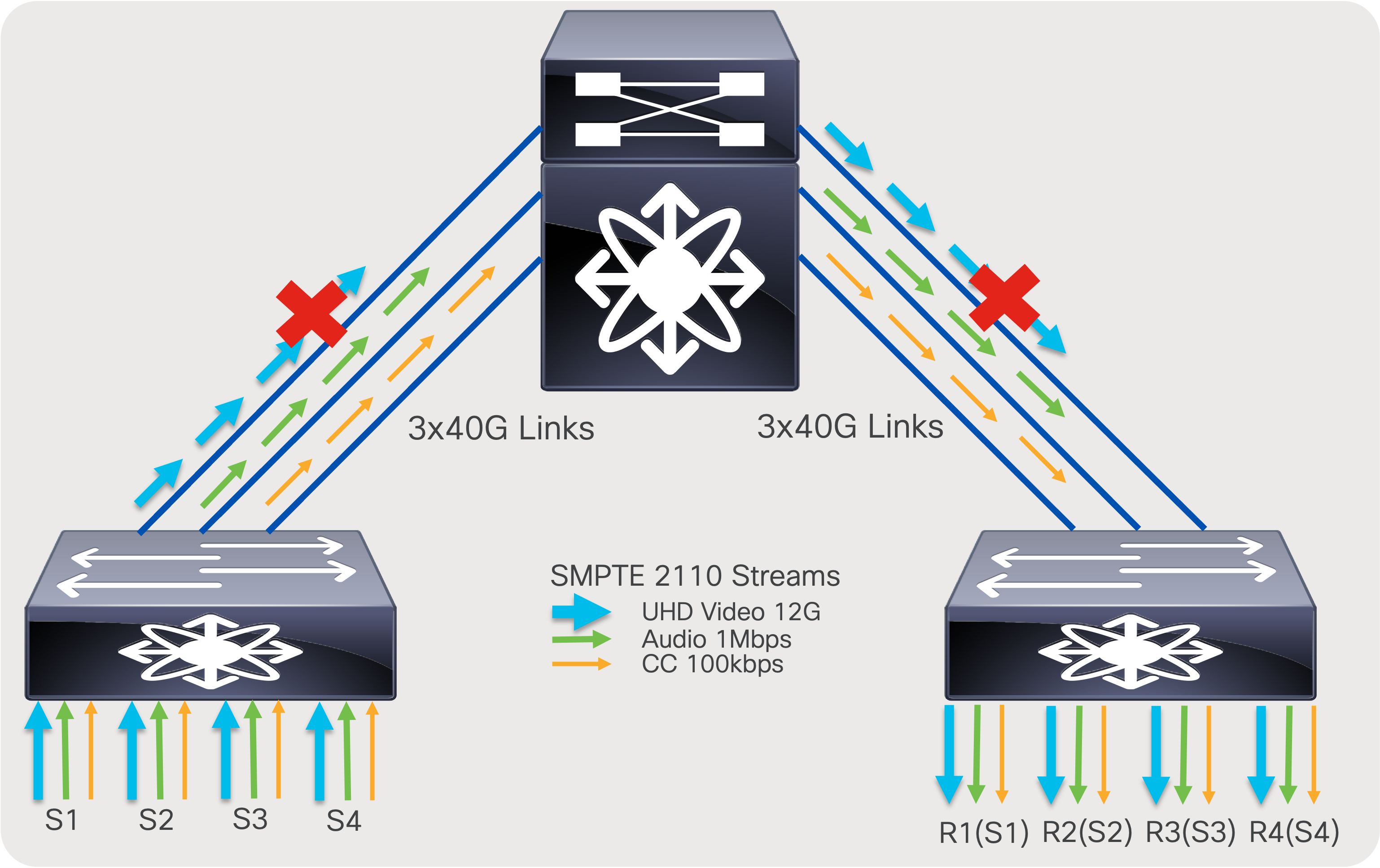
PIM with ECMP based on hash (link oversubscription may occur)
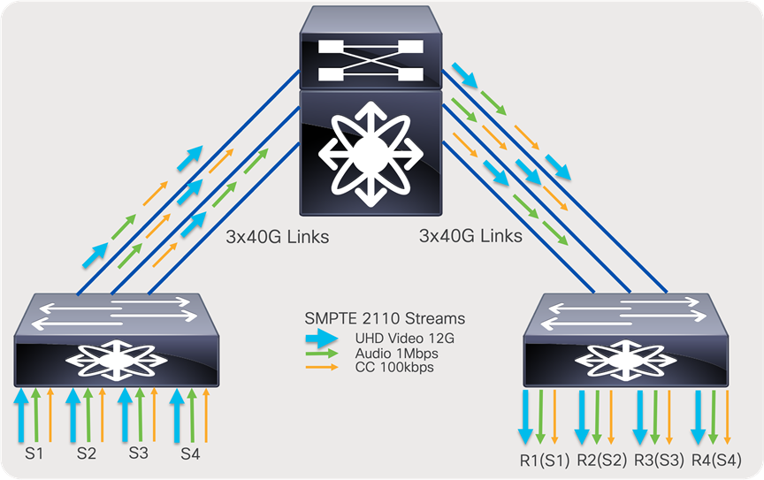
PIM with ECMP and NBM (assures non-oversubscribed multicast transport)
NBM modes: NBM active and NBM passive
As discussed in the previous section, NBM brings bandwidth awareness to PIM. The goal of NBM is to ensure that flows are load balanced and that all paths are utilized, as well as to prevent oversubscription during flow setup or when flows need to be rebalanced in the event of a link failure. NBM can work in two modes: NBM active mode, and NBM passive mode. User chooses what mode to run on a per VRF basis.
In the NBM active mode the responsibility of bandwidth management is with the network and the Nexus switches themselves.
In the NBM passive, the network itself does not take any decision on how flows are routed during flow setup, nor does it take any decision on how flows must be recovered in the event of a failure. NBM passive simply exposes an API, which the SDN controller can instruct with and give instructions on what needs to be done during flow setup as well as flow recovery in the event of a failure.
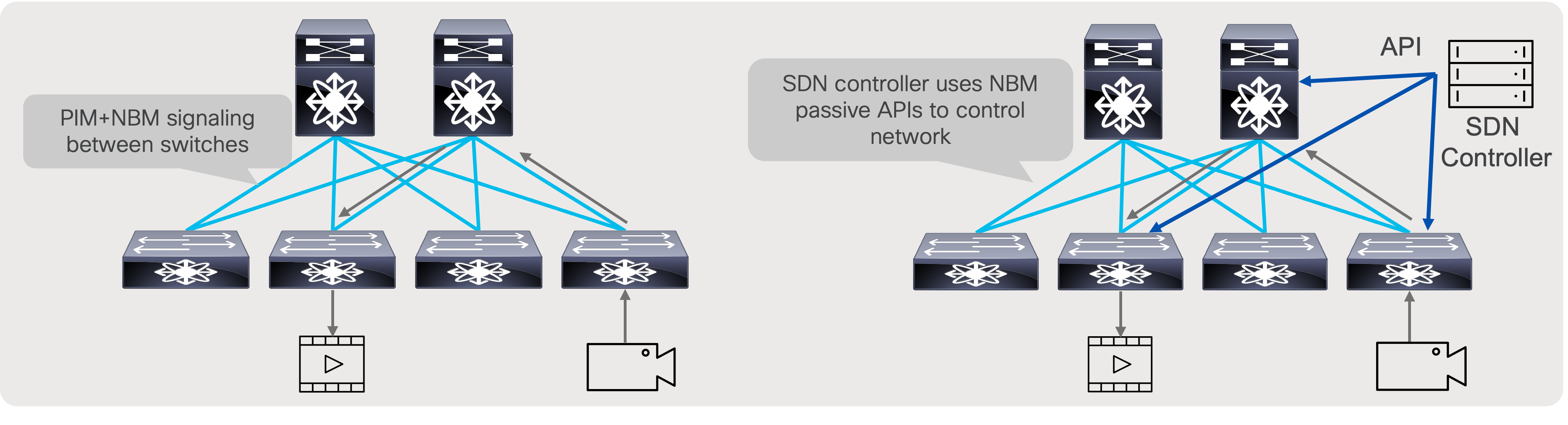
NBM active and NBM passive operation
Designing a non-blocking Spine and Leaf (CLOS) Fabric
SDI routers are non-blocking in nature. Similarly, a single Ethernet switch, such as a Nexus 9500 modular switch, is also non-blocking. Building a network in more scalable way, like a CLOS architecture provides flexibility and scalability. This architecture requires multiple switches to seamlessly work together; a few design details need to be taken into consideration to ensure a CLOS architecture remains non-blocking.
In an ideal scenario, the sender leaf (first-hop router) sends one copy of the flow to one of the spine switches. The spine creates “N” copies, one for each receiver leaf switch that has interested receivers for that flow. The receiver leaf (last-hop router) creates “N” copies of the flow, one per local receiver connected on the leaf. At times, especially when the system is at its peak capacity, you could encounter a scenario where a sender leaf has replicated a flow to a certain spine, but the receiver leaf cannot get traffic from that spine as its link bandwidth to that spine is completely occupied by other flows. When this happens, the sender leaf must replicate the flow to another spine. This results in the sender leaf using twice the bandwidth for a single flow.
To ensure the CLOS network remains non-blocking, a sender leaf must have enough bandwidth to replicate all its local senders to all spines. By following this guideline, the CLOS network can be non-blocking.
The total bandwidth of all senders connected to a leaf must be equal to the bandwidth of the uplinks going from that leaf to each of the spines. The total bandwidth of all receivers connected to a leaf must be equal to the aggregate bandwidth of all uplinks going to all spines from that leaf.
For example, N9K-C93180YC-FX with 6x100G uplinks, as a leaf in two spine design. and 300 Gb going to each spine can support 300 Gb of senders and 600 Gb of receivers connected to the leaf.
In a broadcasting facility, most of the endpoints are unidirectional – camera, microphone, multiviewers, etc. In addition, there are more receivers than senders (a typical ratio is 4:1), and, when a receiver no longer needs a flow, it leaves the flows, freeing up the bandwidth. Hence, the network can be designed with the placement of senders and receivers such that the CLOS architecture becomes non-blocking.
The number and type of leaf and spine switches required in your IP fabric depend on the number and type of endpoints in your broadcasting center.
Follow these steps to help determine the number of leaf switches you need:
Count the number of endpoints (cameras, microphones, gateway, production switchers, etc.) in your broadcasting center. For example, assume that your requirements are as follows:
● Number of 40-Gbps ports required for IPGs: 40
● Number of 10-Gbps ports required for cameras: 150
● Number of 1-Gbps/100M ports required for audio consoles: 50
The uplink bandwidth from a leaf switch to a spine switch must be equal to or greater than the bandwidth provisioned to endpoints.
The Nexus 9336C-FX2 can be used as a leaf switch for 40-Gbps endpoints. Each supports up to 25 x 40-Gbps endpoints and requires 10 x 100-Gbps uplinks.
● The Nexus 93180YC-FX can be used as a leaf switch for 10-Gbps endpoints. Each supports up to 48 x 10-Gbps endpoints and requires 6 x 100-Gbps uplinks.
● The Nexus 9348GC-FXP can be used as a leaf switch for 1G/100M endpoints. Each supports up to 48 x 1G BASE-T endpoints with 2 x 100-Gbps uplinks.
● 40 x 40-Gbps endpoints would require 2 x 9336C-FX2 leaf switches with 20 x 100-Gbps uplinks.
● 160 x 10-Gbps endpoints would require 4 x 93180YC-FX leaf switches with 24 x 100-Gbps uplinks.
● 70 x 1-Gbps endpoints would require 2 x 9348GC-FXP leaf switches with 4 x 100-Gbps uplinks. (Not all uplinks are used.)
● The total number of uplinks required is 48 x 100 Gbps.
● The Nexus 9500 chassis with a N9K-X9636C-R line card or a Nexus 9336C-FX2 can be used as a spine.
● With a Nexus 9336C-FX2 switch, each switch supports up to 36 x 100-Gbps ports. Two spine switches with 24 x 100-Gbps ports per spine can be used (Figure 13), leaving room for future expansion.
● With Nexus 9508 chassis and N9K-X9636C-R line cards, each line card supports 36 x 100-Gbps ports. Two-line cards with a single spine switch can be used (Figure 14), leaving room for future expansion.
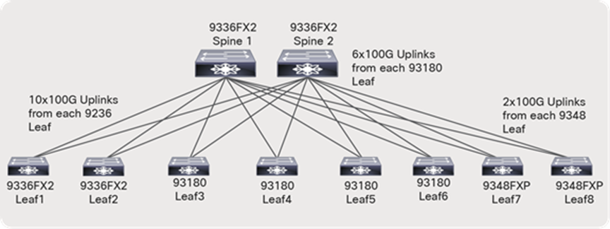
Network topology with a Nexus 9336C-FX2 Switch as the spine
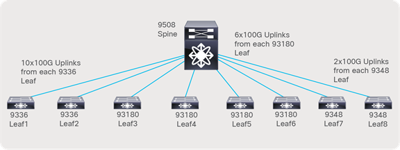
Network topology with the Nexus 9508 Switch as the spine
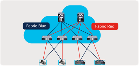
As most deployments utilize network redundancy and hitless merge on destinations (SMTP 2022-7 as an example), the same network is replicated two times, and the endpoints are dual homed to each network (Figure 15).
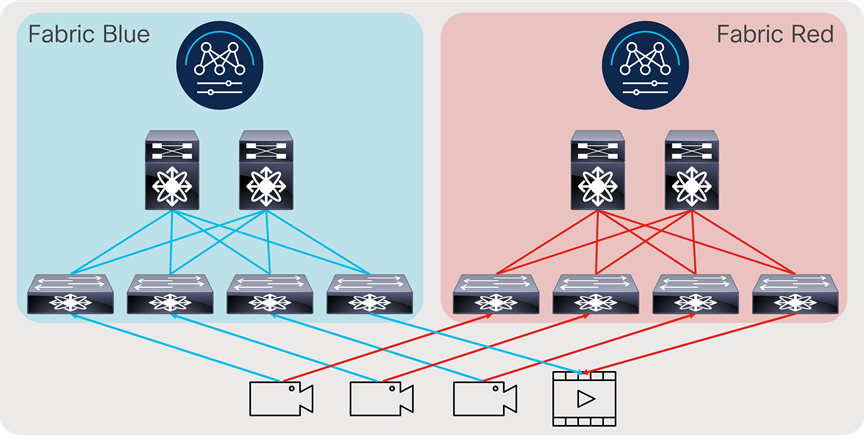
Redundant IP network deployment
Securing the Fabric – NBM Active Mode
In an IP fabric, an unauthorized device could be plugged into the network and compromise production flows. The network must be designed to only accept flows from an authorized source and send flows to an authorized destination. Also, given the network has limited bandwidth, a source must not be able to utilize more bandwidth than what it is authorized to use.
An NBM process provides host policies for use, and the network can restrict what multicast flows a source can transmit to as well as what multicast flows a destination or receiver can subscribe to or join. The NBM active process also provides flow policies to use, and the bandwidth required for a flow or group of flows is specified. NBM utilizes the information in flow policy to reserve end-to-end bandwidth when a flow request is made and programs a policer on the sender switch (first hop) that restricts the source to only transmit the flow at the rate defined by the policy. If a source transmits at a higher rate, the flow is policed where excess traffic is dropped, thereby protecting the network bandwidth and other flows on the fabric.
Host (endpoint) Interface Bandwidth Protection – NBM Active Mode
NBM ensures an endpoint interface is not oversubscribed by only allowing flows that do not exceed the interface bandwidth. As an example, if the flow policy for groups 239.1.1.1 to 239.1.1.10 used by 3Gbps HD video is set to 3.3 Gbps and the source is connected to a 10-Gbps interface, only the first three flows transmitted by the source are accepted. Even if the actual bandwidth utilized is less than the link capacity, NBM reserves bandwidth specified in the flow policy. The fourth flow would exceed 10 Gbps, hence it is rejected.
On the receiver or destination side, the same logic applies. When a receiver tries to subscribe to more traffic than the link capacity allows, the request is denied.
Note: This logic only applies when endpoints are connected using a layer 3 interface and Layer 3 sub-interface. Host interface bandwidth tracking does not apply when endpoints are connected using a layer 2 trunk or access interface, or a port channel.
Prior to configuring NBM, the IP fabric must be configured with a unicast routing protocol such as OSPF, PIM, and Multicast Source Discovery Protocol (MSDP).
Configuring OSPF, PIM, MSDP, and Fabric and Host Links
OSPF configuration on SPINE and LEAF
feature ospf
router ospf 100
interface Ethernet1/1
ip router ospf 100 area 0.0.0.0
ip pim sparse-mode
PIM Configuring on SPINE(s)
feature pim
interface loopback100
Note that loopback is used as RP. Configure same loopback with same IP on all SPINES.
ip address 123.123.123.123/32
ip router ospf 100 area 0.0.0.0
ip pim sparse-mode
A multicast RP is needed only when ASM (any source multicast) is used. If the facility uses SSM, RP is not needed for those multicast groups.
ip pim rp-address 123.123.123.123 group-list <asm group list>
ip pim prune-on-expiry
ip pim ssm range none
ip pim spt-threshold infinity group-list spt
route-map spt permit 10
match ip multicast group <asm range>
interface ethernet1/1
ip address 1.1.1.1/30
ip pim sparse-mode
Note: “ip pim ssm range none” does not disable source-specific multicast (SSM). SSM is still supported for any range where receivers send IGMPv3 reports.
PIM Configuring on Leaf
feature pim
A multicast RP is needed only when ASM (any source multicast) is used. If the facility uses SSM, RP is not needed for those multicast groups.
ip pim rp-address 123.123.123.123 group-list <asm range>
ip pim prune-on-expiry
ip pim ssm range none
ip pim spt-threshold infinity group-list spt
route-map spt permit 10
match ip multicast group <asm range>
interface ethernet1/49
ip address 1.1.1.1/30
ip pim sparse-mode
MSDP is needed only when ASM (any source multicast) is used. If the facility uses SSM, MSDP is not needed for those multicast groups.
Configuring MSDP on SPINES (RP)
Configuration on Spine 1
feature msdp
interface loopback0
ip pim sparse-mode
ip address 77.77.77.1/32
ip router ospf 100 area0
ip msdp originator-id loopback0
ip msdp peer 77.77.77.2 connect-source loopback0
ip msdp sa-policy 77.77.77.2 msdp-mcast-all out
ip msdp mesh-group 77.77.77.2 spine-mesh
route-map msdp-mcast-all permit 10
match ip multicast group 224.0.0.0/4
Configuration on Spine 2
feature msdp
Interface loopback0
ip pim sparse-mode
ip address 77.77.77.2/32
ip router ospf 100 area0
ip msdp originator-id loopback0
ip msdp peer 77.77.77.1 connect-source loopback0
ip msdp sa-policy 77.77.77.1 msdp-mcast-all out
ip msdp mesh-group 77.77.77.1 spine-mesh
route-map msdp-mcast-all permit 10
match ip multicast group 224.0.0.0/4
Configuring fabric link – links between network switches
When multiple links exist between switches, configure them as individual point-to-point Layer-3 links.
Note: Do not bundle the links in port-channel.
interface Ethernet1/49
ip address x.x.x.x/y
ip router ospf 100 area 0.0.0.0
ip pim sparse-mode
no shutdown
Configuring Host (Endpoint) Link – Links between the Network Switch and Endpoint
Endpoints, which are typically sources and destinations, can be connected using a layer 3 interface. Or connected using Layer-2 trunk/access interface with Switch Virtual Interface (SVI) on the switch.
Layer 3 interface towards endpoint
interface Ethernet1/1
ip address x.x.x.x/y
ip router ospf 100 area 0.0.0.0
ip ospf passive-interface
ip pim sparse-mode
ip igmp version 3
ip igmp immediate-leave
ip igmp suppress v3-gsq
no shutdown
Layer 2 interface (trunk or access) towards endpoint
interface Ethernet1/1
switchport
switchport mode <trunk|access>
switchport access vlan 10
switchport trunk allowed vlan 10,20
spanning-tree port type edge trunk
interface vlan 10
ip address x.x.x.x/y
ip router ospf 100 area 0.0.0.0
ip ospf passive-interface
ip pim sparse-mode
ip igmp version 3
ip igmp immediate-leave
no shutdown
vlan configuration 10
ip igmp snooping fast-leave
Configuring NBM in Active Mode
Before NBM can be enabled, the network must be preconfigured with IGP, PIM, and MSDP (when applicable). NBM configuration must be completed before connecting sources and destinations to the network. Failing to do so could result in NBM not computing the bandwidth correctly. As a best practice, keep the endpoint-facing interface administratively down, complete NBM configuration, and re-enable the interfaces.
Enabling NBM feature
feature nbm
Enabling NX-API
feature nxapi
NBM is notified to operate in pim active mode.
nbm mode pim-active
Carve TCAM needed for NBM to program QOS and flow policers. Reload is required post TCAM carving.
For Nexus 9300:
hardware access-list tcam region ing-racl 256
hardware access-list tcam region ing-l3-vlan-qos 256
hardware access-list tcam region ing-nbm 1536
For Nexus 9500 with 9600-R line cards:
hardware access-list tcam region redirect_v6 0
hardware access-list tcam region ing-nbm 2048
For Nexus 9800 TCAM is allocated by default to NBM region.
Defining ASM range
This is needed in a multi-spine deployment to ensure efficient load balancing of ASM flows. SSM flow range do not need to be defined in this CLI.
ASM flow is the multicast range where destinations or receivers use IGMPv2 join.
nbm flow asm range 238.0.0.0/8 239.0.0.0/8
Define Flow Policies
Flow policies are defined for the following benefits:
● flow polices describe flow parameters such as bandwidth and DSCP(QOS).
● flow policies must be defined on all switches in the fabric and must be the same.
● default flow policy applies to multicast groups which does not have specific policy.
● default flow policy is set to 0 and can be modified if needed.
nbm flow bandwidth 0 kbps
User defined custom flow policy
nbm flow-policy
!policy <NAME>
!bandwidth <bandwidth_reservation>
!dscp <value>
!ip group-range first_multicast_ip_address to last_multicast_ip_address
policy Ancillary
bandwidth 1000 kbps
dscp 18
ip group-range 239.1.40.0 to 239.1.40.255
policy Audio
bandwidth 2000 kbps
dscp 18
ip group-range 239.1.30.0 to 239.1.30.255
policy Video_1.5
bandwidth 1600000 kbps
dscp 26
ip group-range 239.1.20.1 to 239.1.20.255
Verify Flow Policy
N9K# show nbm flow-policy
--------------------------------------------------------------------------------
| Group Range | BW (Kbps) | DSCP | QOS | Policy Name
--------------------------------------------------------------------------------
| 239.1.40.0-239.1.40.255 | 1000 | 0 | 7 | Ancillary
| 239.1.30.0-239.1.30.255 | 2000 | 18 | 7 | Audio
| 239.1.20.1-239.1.20.255 | 1600000 | 26 | 7 | Video_1.5
--------------------------------------------------------------------------------
Policy instances printed here = 3
Total Policies Defined = 3
NBM host policy can be applied to sender or sources, receiver (local) or pim (external receivers).
NBM default host policy is set to permit all and can be modified to deny if needed 224.0.0.0/4 matches all multicast addresses and can be used to match all for multicast.
nbm host-policy
sender
default deny
! <seq_no.> host <sender_ip> group <multicast_group> permit|deny
10 host 192.168.105.2 group 239.1.1.1/32 permit
1000 host 192.168.105.2 group 239.1.1.2/32 permit
1001 host 192.168.101.2 group 239.1.1.0/24 permit
1002 host 192.168.101.3 group 225.0.4.0/24 permit
1003 host 192.168.101.4 group 224.0.0.0/4 permit
nbm host-policy
receiver
default deny
!<seq_no.> host <receiver_ip> source <> group <multicast_group> permit|deny
100 host 192.168.101.2 source 192.205.38.2 group 232.100.100.0/32 permit
10001 host 192.168.101.2 source 0.0.0.0 group 239.1.1.1/32 permit
10002 host 192.168.102.2 source 0.0.0.0 group 239.1.1.0/24 permit
10003 host 192.168.103.2 source 0.0.0.0 group 224.0.0.0/4 permit
Verify sender policies configured on the switch
N9K# show nbm host-policy all sender
Default Sender Policy: Deny
Seq Num Source Group Mask Action
10 192.168.105.2 233.0.0.0 8 Allow
1000 192.168.101.2 232.0.0.0 24 Allow
1001 192.168.101.2 225.0.3.0 24 Allow
1002 192.168.101.2 225.0.4.0 24 Allow
1003 192.168.101.2 225.0.5.0 24 Allow
Verify sender policies applied to local senders attached to that switch
N9K# show nbm host-policy applied sender all
Default Sender Policy: Deny
Applied host policy for Ethernet1/31/4
Seq Num Source Group Mask Action
20001 192.26.1.47 235.1.1.167 32 Allow
Total Policies Found = 1
Verify receiver policies configured on the switch
N9k# show nbm host-policy all receiver local
Default Local Receiver Policy: Allow
Seq Num Source Group Mask Reporter Action
10240 192.205.38.2 232.100.100.9 32 192.168.122.2 Allow
10496 192.205.52.2 232.100.100.1 32 192.168.106.2 Allow
12032 0.0.0.0 232.100.100.32 32 192.169.113.2 Allow
12288 0.0.0.0 232.100.100.38 32 192.169.118.2 Allow
12544 0.0.0.0 232.100.100.44 32 192.169.123.2 Allow
N9k# show nbm host-policy applied receiver local all
Default Local Receiver Policy: Allow
Interface Seq Num Source Group Mask Action
Ethernet1/1 10240 192.205.38.2 232.100.100.9 32 Allow
Total Policies Found = 1
If an SDN controller is used to program flow path, NBM must work in pim-passive or passive mode. Below are the configurations needed to enable SDN control. The flow setup using SDN control is only available via API (no CLIs are exposed). Details of the APIs are available on the Cisco developer website.
Configuring OSPF, PIM, and Fabric and Host Links
OSPF Configuration on SPINE and LEAF
feature ospf
router ospf 100
interface Ethernet1/1
ip router ospf 100 area 0.0.0.0
ip pim sparse-mode
PIM Configuring on SPINE(s)
feature pim
ip pim ssm range none
interface ethernet1/1
ip address 1.1.1.1/30
ip pim sparse-mode
ip pim passive
! PIM Configuring on Leaf
feature pim
ip pim ssm range none
interface ethernet1/49
ip address 1.1.1.1/30
ip pim sparse-mode
ip pim passive
Configuring fabric link – links between network switches.
When multiple links exist between switches, configure them as individual point-to-point layer-3 links.
Note: Do not bundle the links in port-channel.
interface Ethernet1/49
ip address x.x.x.x/y
ip router ospf 100 area 0.0.0.0
ip pim sparse-mode
ip pim passive
no shutdown
Configuring host (endpoint) link – links between the network switch and endpoint.
Endpoints, which are typically sources and destinations, can be connected using a layer-3 interface. Or connected using layer-2 trunk/access interface with Switch Virtual Interface (SVI) on the switch.
Layer 3 interface towards endpoint
interface Ethernet1/1
ip address x.x.x.x/y
ip router ospf 100 area 0.0.0.0
ip ospf passive-interface
ip pim sparse-mode
ip pim passive
no shutdown
Layer 2 interface (trunk or access) towards endpoint
interface Ethernet1/1
switchport
switchport mode <trunk|access>
switchport access vlan 10
switchport trunk allowed vlan 10,20
spanning-tree port type edge trunk
interface vlan 10
ip address x.x.x.x/y
ip router ospf 100 area 0.0.0.0
ip ospf passive-interface
ip pim sparse-mode
ip pim passive
vlan configuration 10
ip igmp snooping fast-leave
Configuring NBM in Passive Mode
Before NBM can be enabled, the network must be preconfigured with IGP, PIM.
Enabling NBM feature
feature nbm
Enabling NX-API
feature nxapi
NBM is notified to operate in pim active mode.
nbm mode pim-passive
Carve TCAM needed for NBM to program QOS and flow policers. Reload required post TCAM carving.
For Nexus 9300:
hardware access-list tcam region ing-racl 256
hardware access-list tcam region ing-l3-vlan-qos 256
hardware access-list tcam region ing-nbm 1536
For Nexus 9500 with 9600-R line cards:
hardware access-list tcam region redirect_v6 0
hardware access-list tcam region ing-nbm 2048
For Nexus 9800 TCAM is allocated by default to NBM region.
Nexus Dashboard Fabric Controller (NDFC) for Media Fabrics
Cisco Nexus Dashboard Fabric Controller aka NDFC (formerly known as Data Center Network Manager aka DCNM) runs exclusively as an application on the Cisco Nexus Dashboard Cluster. Nexus Dashboard cluster uses Kubernetes at its core with customized extensions, thereby realizing secure and scaled-out platform for deployment of microservices-based applications. Nexus Dashboard Cluster provides Active/Active HA (High Availability) for all applications running on top of that cluster.
NDFC for IP Fabric for Media brings fabric-oriented configuration and operations management. NBM active mode provides multicast transport and security with host and flow policies. Nexus Dashboard Fabric Controller complements NBM, providing visibility and analytics of all the flows in the fabric. NDFC can also be used to configure fabric in the beginning, including configuring the IGP (OSPF), PIM, and MSDP using IP Fabric for Media (IPFM) fabric templates to follow configuration best practices. NDFC can further be used to manage host and flow policies and ASM range, unicast bandwidth reservation, network address translations, and external link for multi-site deployments.
NDFC uses NX-API to send policies and configurations to the switch, and the NBM process uses NX-OS streaming telemetry to stream state information to NDFC (Figure 16). NDFC collects information from individual switches in the fabric, correlates them, and presents flows in graphical form. Furthermore, NDFC enables representation state transfer (RESTful) APIs to allow easy integration of Broadcast Controllers to enable automation to meet customers’ needs.
To summarize, NDFC can help with:
● Fabric configuration using NDFC fabric template, to automate network bringup.
● Topology and host discovery to dynamically discover the topology and host connectivity.
● Flow and host policy manager
● End-to-end flow visualization with flow statistics
● The API gateway for the broadcast controller
● Network health monitoring
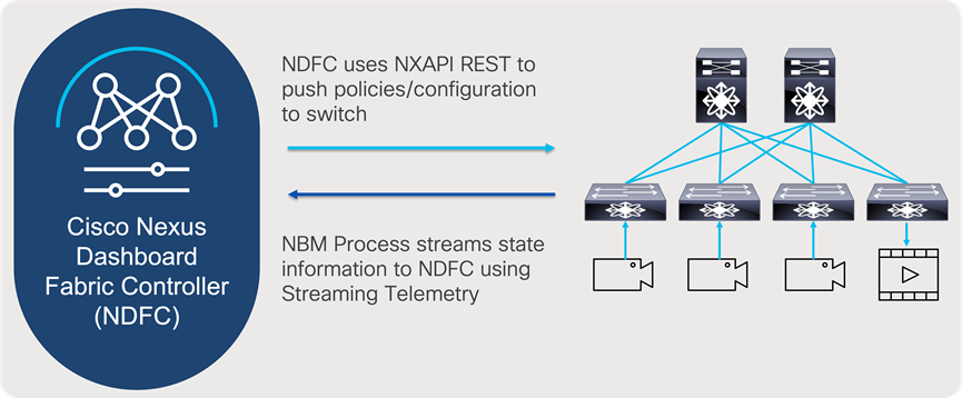
NDFC and NBM interaction
Cisco Nexus Dashboard and Nexus Dashboard Fabric Controller Deployment Options
Nexus Dashboard (ND) as microservices platform hosting NDFC application for IP Fabric for media, can be hosted on physical Nexus Dashboard (pND) cluster as well on a virtual platform (vND), hosted on a hypervisor.
For the deployment options of Nexus Dashboard, how to install it, see deployment guides: https://www.cisco.com/c/en/us/support/data-center-analytics/nexus-dashboard/products-installation-guides-list.html.
Nexus Dashboard for NDFC Deployment Options
To connect Nexus Dashboard and NDFC to the network, users can use management interface that allows access to ND graphical user interface, access to CLI, DNS, NTP, and Cisco DC App Store. In addition to management interface, data interface is available that allows ND clustering, as well import of telemetry data from network.
To consider all the options available to connect your IPFM fabric with Nexus Dashboard cluster for use by NDFC, please consider Cisco Nexus Dashboard Fabric Controller Deployment Guide.
For the steps to install the NDFC for media deployment, see: https://www.cisco.com/c/en/us/support/cloud-systems-management/prime-data-center-network-manager/products-installation-guides-list.html.
For initial installation configuration of NDFC deployment, please refer to Cisco NDFC-Fabric Controller Configuration Guide, under LAN chapter for IPFM installation: https://www.cisco.com/c/en/us/support/cloud-systems-management/prime-data-center-network-manager/products-installation-and-configuration-guides-list.html.
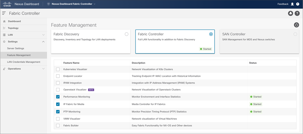
NDFC feature manager, to enable IP Fabric for Media Fabric Network Controller
When users access NDFC, they can start configuring new fabric or importing existing networks into NDFC. To achieve this, two types of fabrics options are present, IP Fabric For Media (IPFM) template and Classic IPFM template. Following, two fabric types are explained in detail as well process of creating fabric and importing switch.
NDFC – IP Fabric for Media Fabric Template
NDFC Fabric Template for IP Fabric for Media, brings easy-to-understand as simple deployment approach to bring greenfield fabrics for IPFM. IPFM best practices are built into the fabric templates, and automated fabric bring up occurs with the click of a button, reducing provisioning times and simplifying deployments.
NDFC fabric template, can configure switches that are already configured with management network, and configure rest of the best practices in topology. User can select option to perform fabric bootstrap, using POAP (Power on Auto Provisioning).
NDFC comes with fabric template, and options for system to perform network discovery on already configured management network and configure inter-switch interface in spine and leaf network. As an option in fabric configuration system can allow switched to be bootstrapped at the time they are added to the fabric.
NDFC fabric configuration steps are described in Figures 18 through 24.
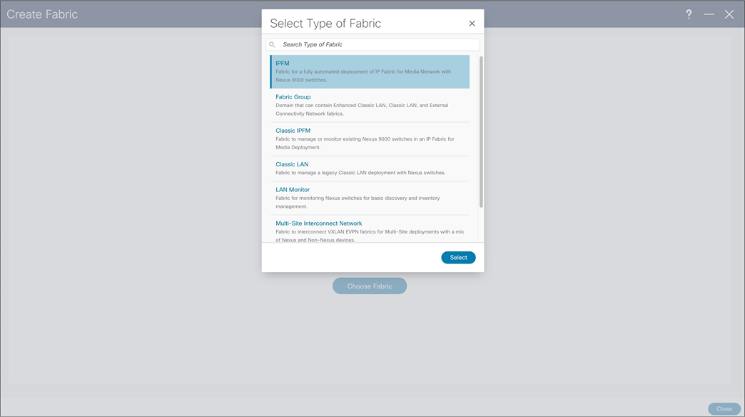
NDFC > Fabric > Create Fabric
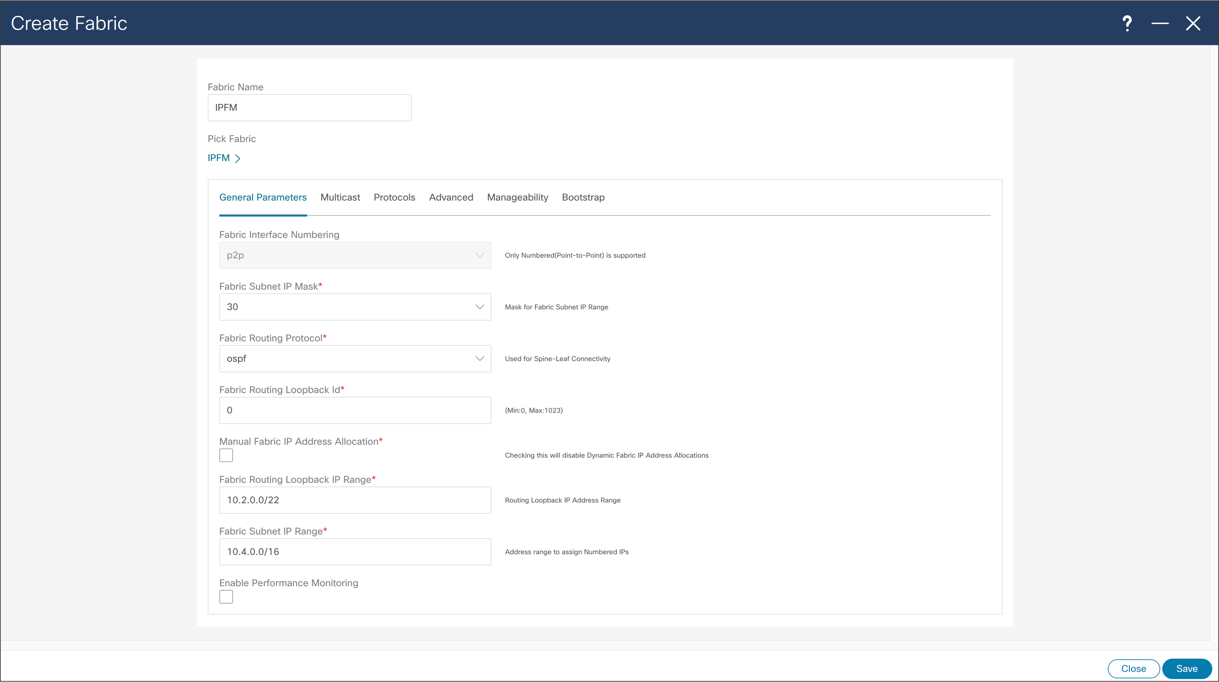
NDFC > Fabric > Create Fabric > General Parameters
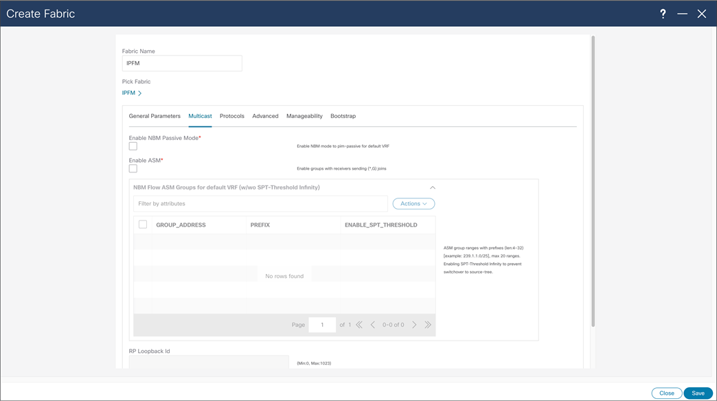
NDFC > Fabric > Create Fabric > Multicast

NDFC > Fabric > Create Fabric > Protocols
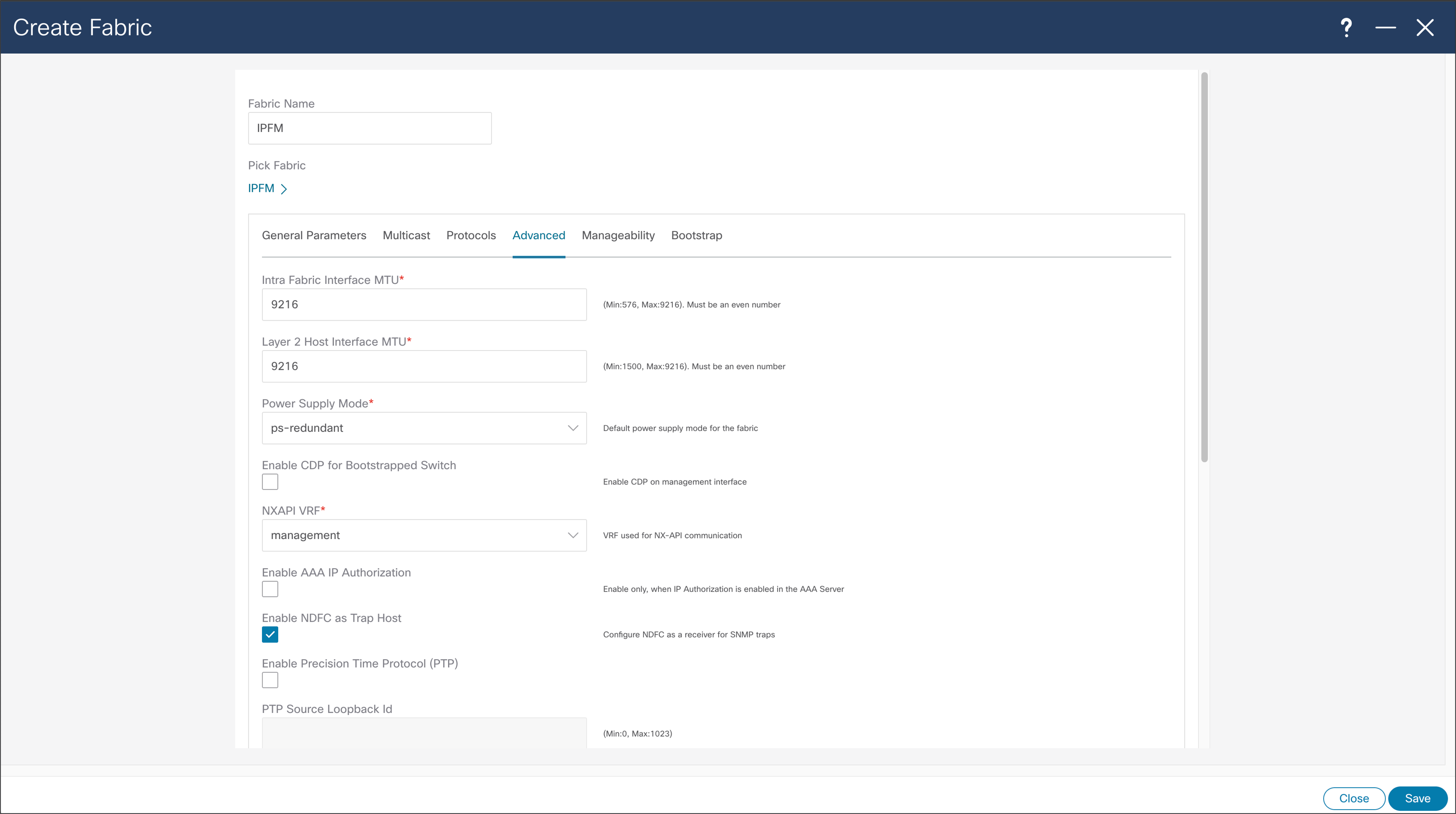
NDFC > Fabric > Create Fabric > Advanced
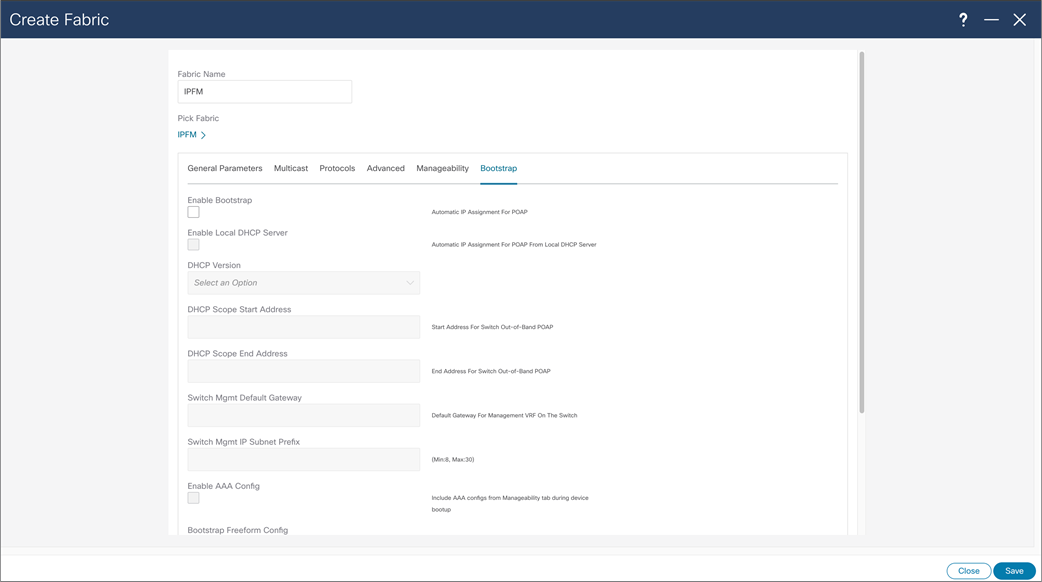
NDFC > Fabric > Create Fabric > Bootstrap
With NBM passive mode, NDFC can be used for network configuration provisioning. At the time of fabric creation user can select fabric to be configured in passive more, similarly to previous fabric creation process. NDFC can as well provide monitoring capabilities for NBM passive fabric.
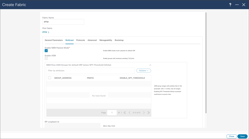
NDFC > Fabric > Create Fabric > Multicast > Enabling NBM Passive Mode
Classic IPFM Template, brings easy-to-understand as simple deployment approach to import existing fabrics in NDFC. Classic IPFM template preserves fabric configuration on the switch, allowing easy migration from DCNM to NDFC.
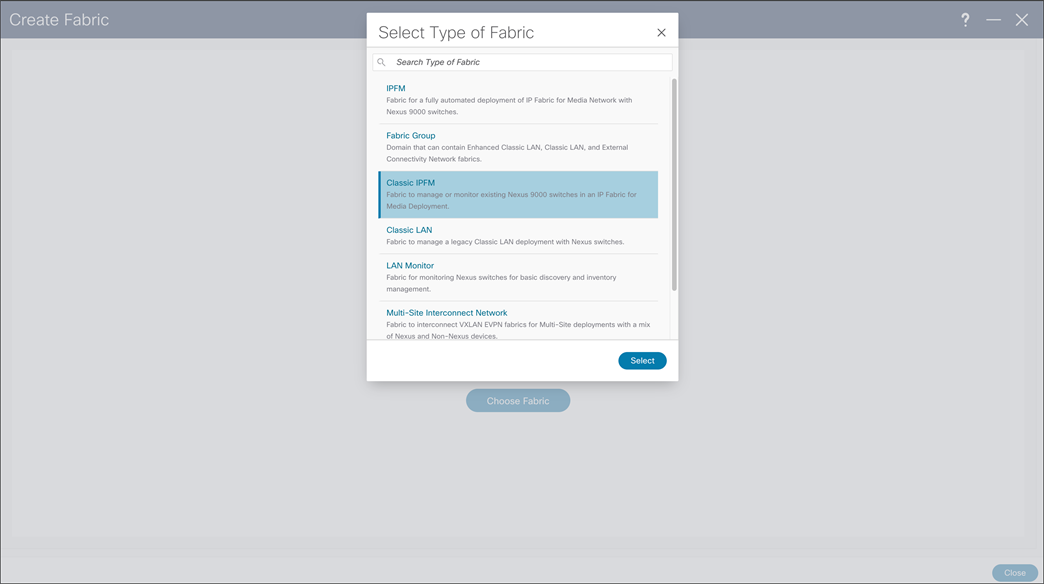
NDFC > Fabric > Create Fabric
Configuration options of Classic IPFM template are simple, as main use case importing already configured fabric using CLI. After configuring options are selected, the same steps as IPFM template need to be performed.
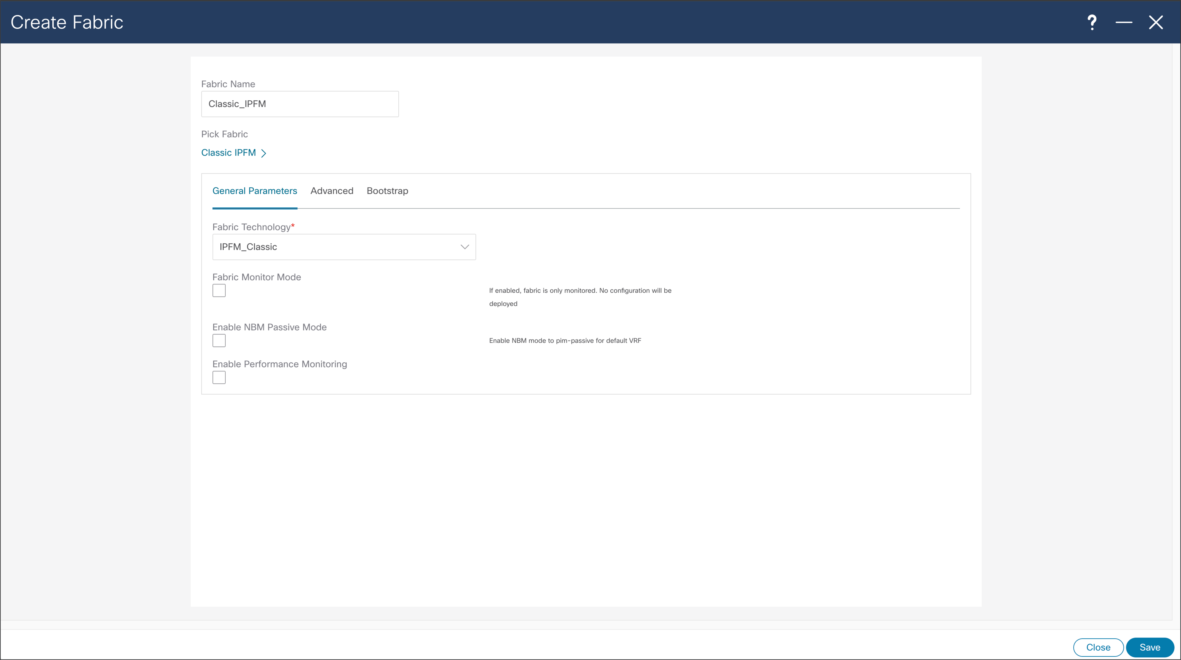
NDFC > Fabric > Create Fabric > General Parameters
NDFC Fabric Template will execute configuration present in the template. For configuration to be deployed to the switches, user is required to add switches to the fabric, and deploy configuration. User might need to change role of added switches, so they are matching role in the fabric, as leaf or as a spine. Figures 27 through 32 show the steps required to discover the fabric.
The NDFC automatically discovers the topology when fabric is provisioned using Fabric template. If the fabric is provisioned through the CLI and through IPFM Classic Template, the switches need to be discovered by NDFC in the same way.
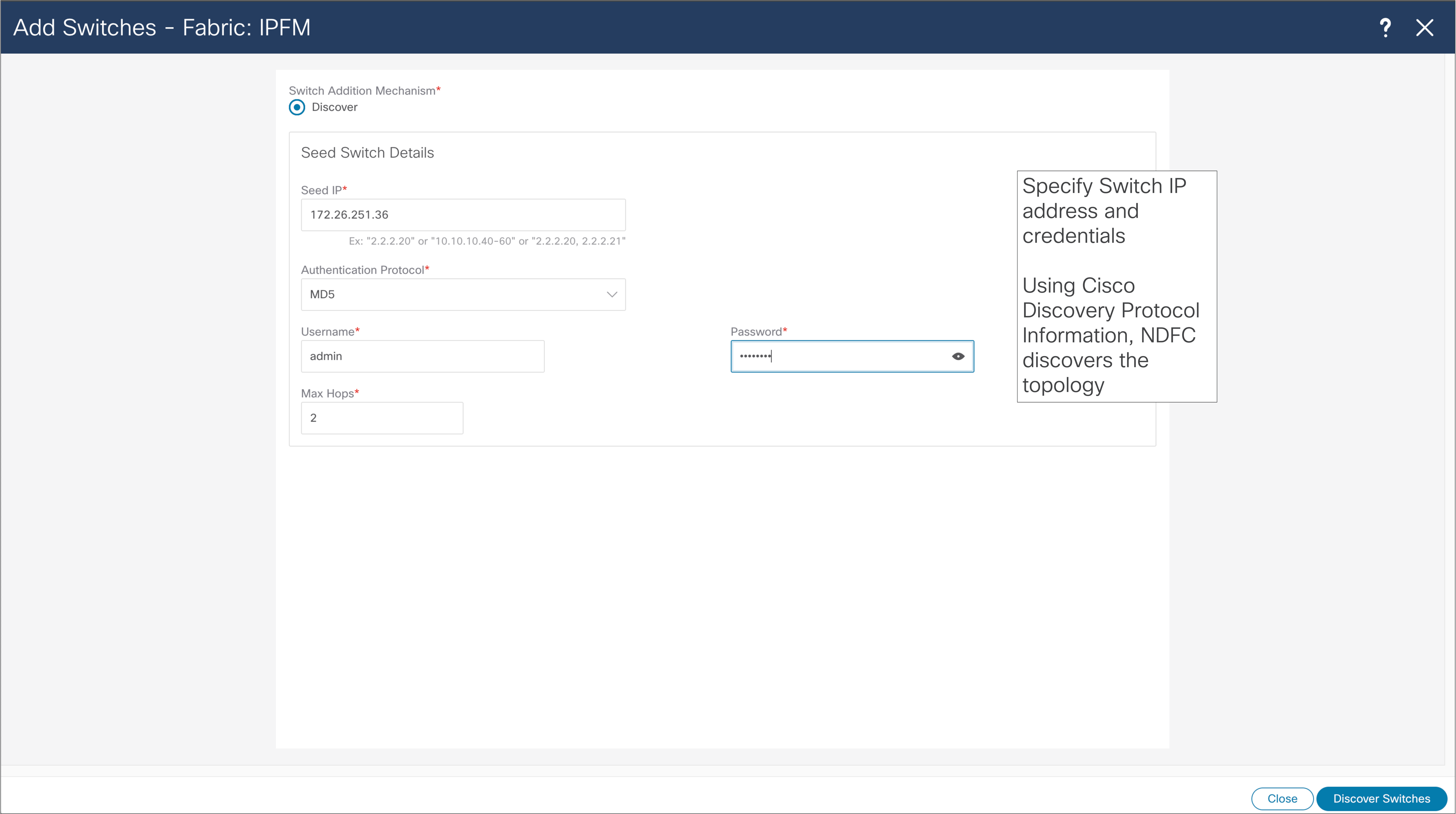
NDFC > LAN > Fabric > Switches > Action > Add Switches
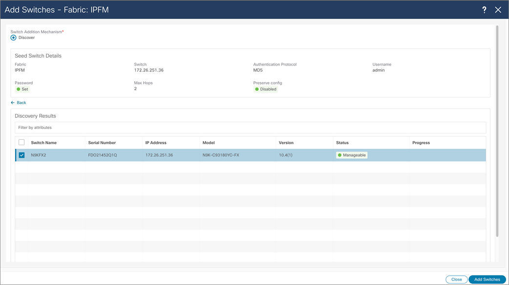
NDFC > LAN > Fabric > Switches > Action > Add Switches > Discovery Results
After the wanted switches are discovered, the user can add those to the fabric by clicking “Add Switches” button. NDFC adds and displays switches in the Fabric menu. Some switches may require a role change, so they can match the designated network role. After roles are selected, the user should Recalculate and Deploy fabric, and NDFC will deploy desirable configuration to the switches.
For Classic IPFM fabric type, this is where some additional configuration is added, for example SNMP server on the switches.
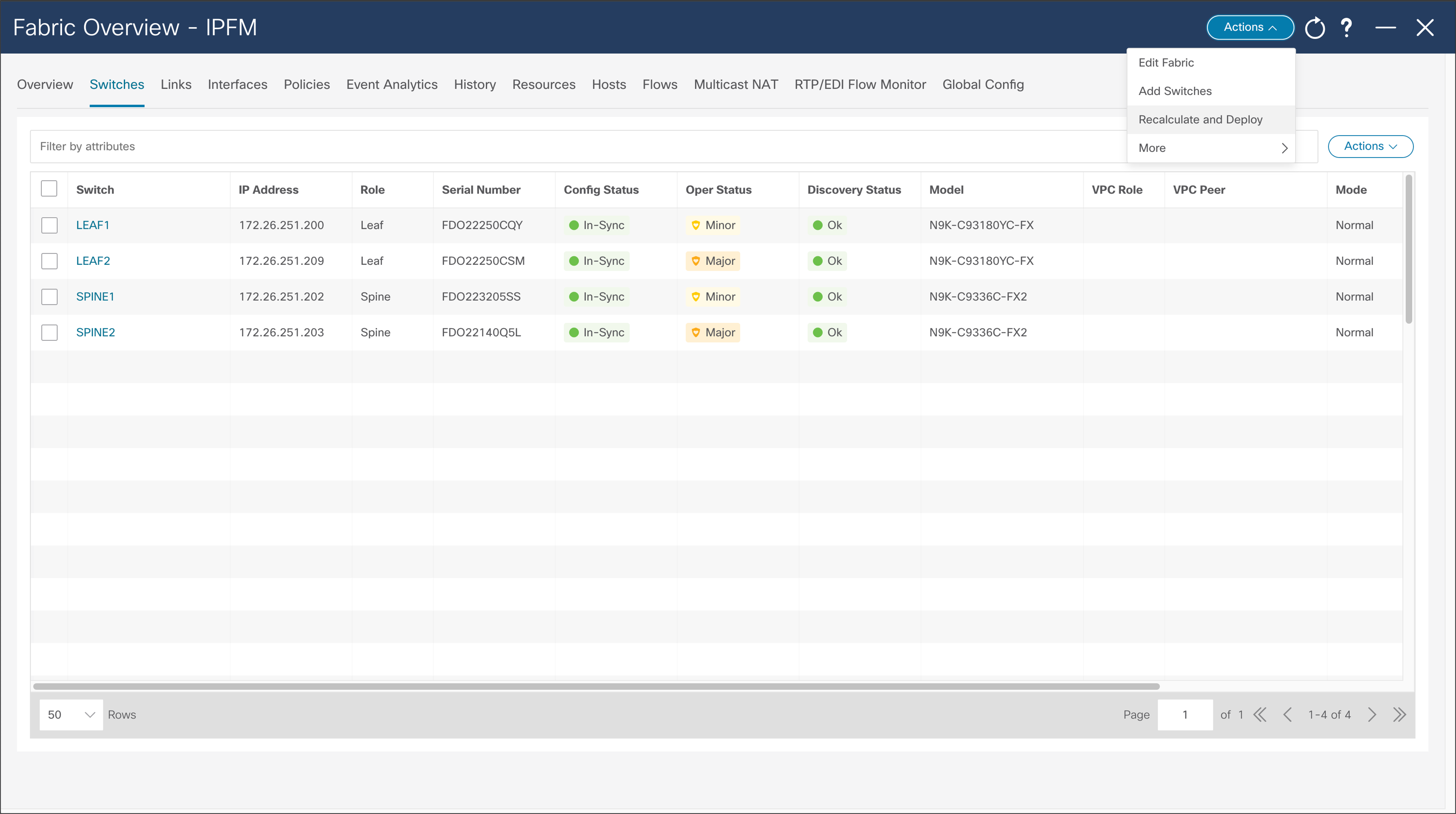
NDFC > LAN > Fabric > Action > Recalculate and Deploy
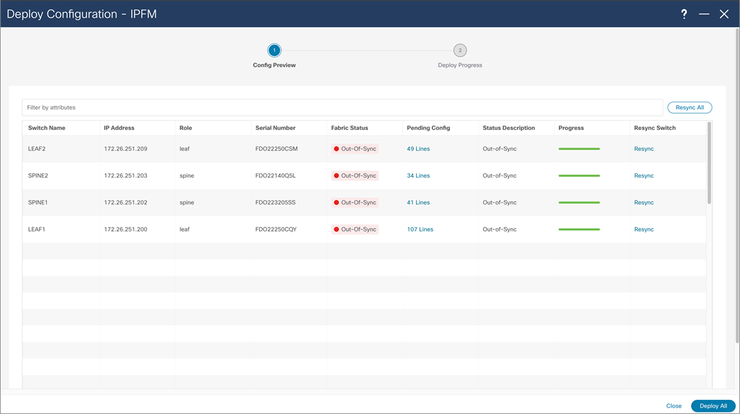
NDFC > LAN > Fabric > Action > Recalculate and Deploy > Deploy Configuration
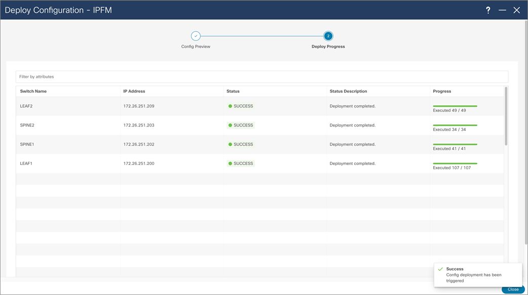
NDFC > LAN > Fabric > Action > Recalculate and Deploy > Deploy Configuration
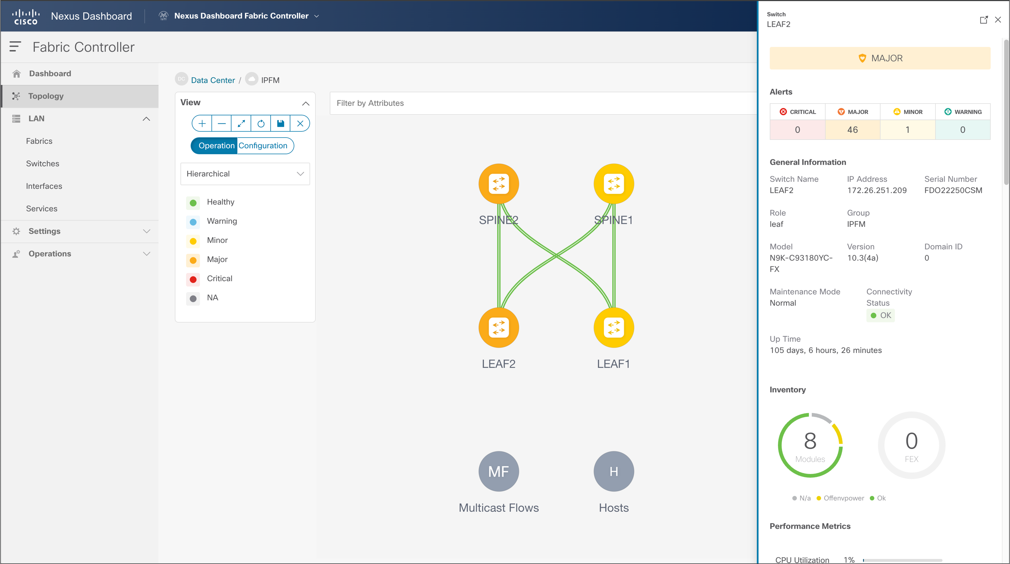
NDFC > Topology
Configuring Switch Telemetry for NDFC and Third-party consumption
For NDFC to expose graphical presentation of flows traversing fabric, and host information, each switch is required to be enabled and configured for telemetry. Telemetry can be enabled through a template in NDFC for IPFM fabric and Classic IPFM fabric. The Classic IPFM fabric allows configuration through CLI for IPFM Classic fabric or Third-party consumption.
To configure telemetry through NDFC, follow these steps:
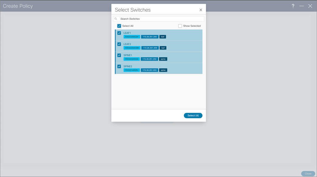
NDFC > LAN > Fabric > Policies > Action > Add Policies > Switch Selection
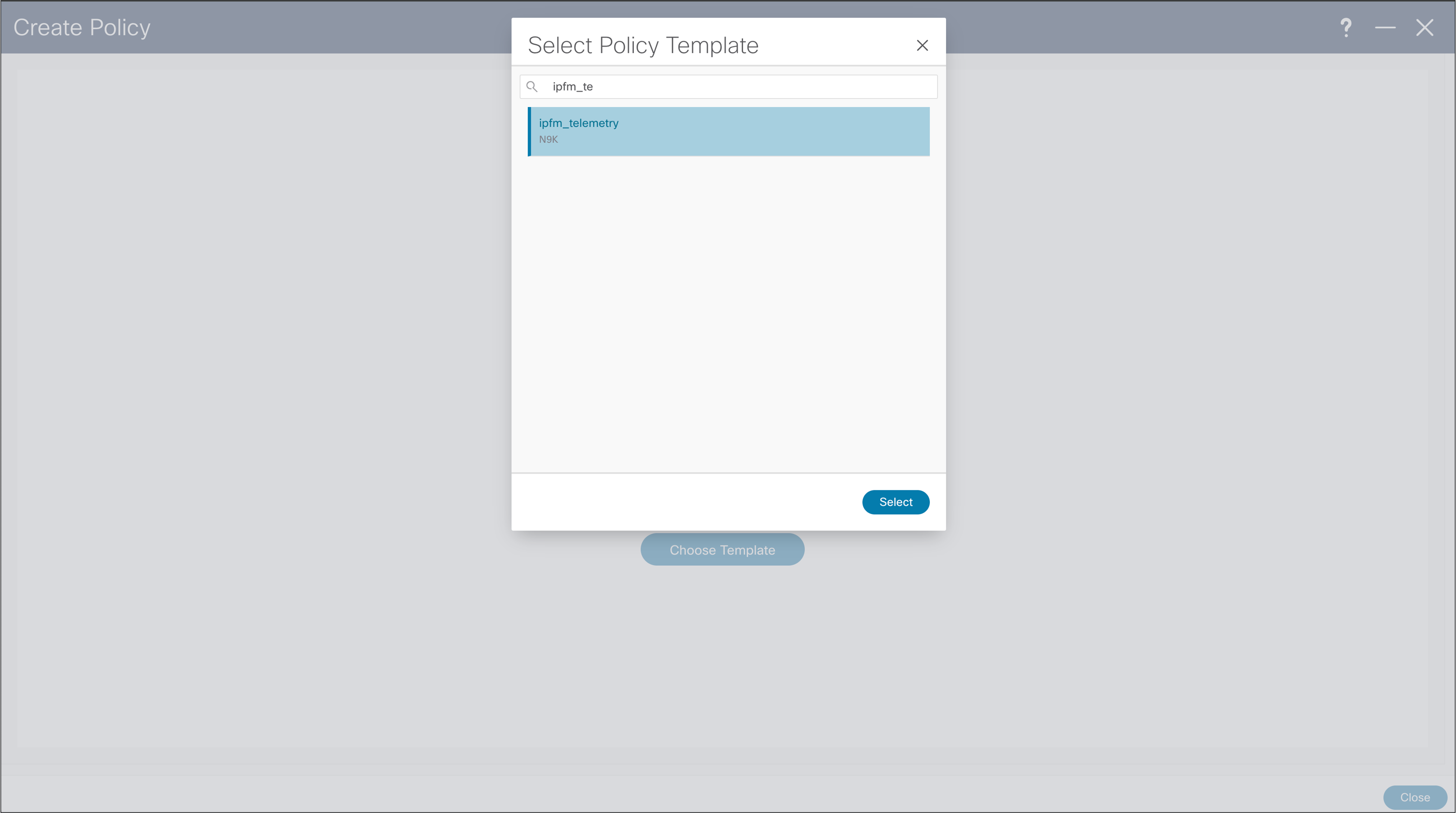
NDFC > LAN > Fabric > Policies > Action > Add Policies > Policy Template
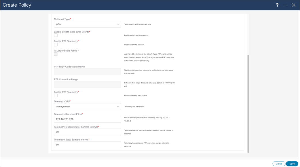
NDFC > LAN > Fabric > Policies > Action > Add Policies > Create Policy
When creating Telemetry Policy, template will ask for “Telemetry Receiver IP List” referring to telemetry receiver of NDFC to consume telemetry coming from switches. This list of IPs can be found in Nexus Dashboard, cluster configuration, and in External Service Pools, ip under name “cisco-ndfc-dcnm-pmn-telemetry-mgmt” if telemetry is sent over management/out of band interface of the switches. In deployment with multiple Nexus Dashboard nodes, user should use all the listed IPs per each node. After the policy is saved, configuration needs to be recalculated and deployed.
Below is example required telemetry configuration for consumption of third party or NDFC in IPFM classic template:
Telemetry configuration on all network switches
feature telemetry
telemetry
destination-profile
use-vrf management
destination-group 200
ip address <NDFC telemetry receiver IP address> port 50051 protocol gRPC encoding GPB
sensor-group 200
path sys/nbm/show/appliedpolicies depth unbounded
path sys/nbm/show/stats depth unbounded
sensor-group 201
path sys/nbm/show/flows query-condition rsp-subtree-filter=eq(nbmNbmFlow.bucket,"1")&rsp-subtree=full
sensor-group 202
path sys/nbm/show/flows query-condition rsp-subtree-filter=eq(nbmNbmFlow.bucket,"2")&rsp-subtree=full
sensor-group 203
path sys/nbm/show/flows query-condition rsp-subtree-filter=eq(nbmNbmFlow.bucket,"3")&rsp-subtree=full
sensor-group 204
path sys/nbm/show/flows query-condition rsp-subtree-filter=eq(nbmNbmFlow.bucket,"4")&rsp-subtree=full
sensor-group 205
path sys/nbm/show/endpoints depth unbounded
subscription 201
dst-grp 200
snsr-grp 200 sample-interval 60000
snsr-grp 201 sample-interval 30000
snsr-grp 205 sample-interval 30000
subscription 202
dst-grp 200
snsr-grp 202 sample-interval 30000
subscription 203
dst-grp 200
snsr-grp 203 sample-interval 30000
subscription 204
dst-grp 200
snsr-grp 204 sample-interval 30000
Host interfaces need to be configured in line with a way of connecting end points. In this example you see how to configure Layer 3 interface for host connectivity. Users can change interface policy, to configure this interface as a Layer 2 (trunk or access) port and configure appropriate parameters.
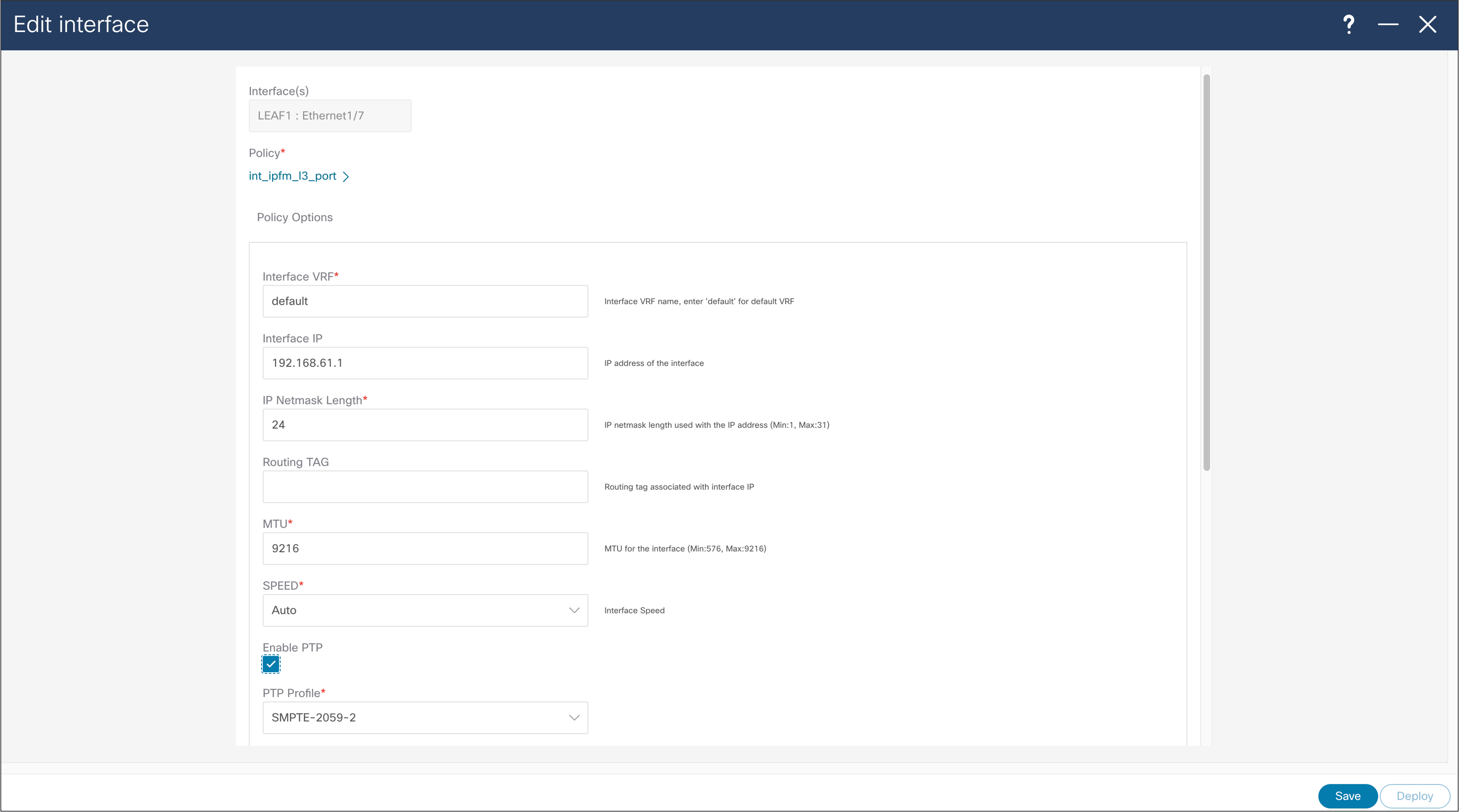
NDFC > LAN > Interface > Edit Interface
When importing existing fabric into NDFC, using Classic IPFM fabric, to import port configuration from switch in NDFC, user can use “host_port_resync” policy template. This will allow NDFC to be single source of interface configuration in Classic IPFM deployment. After the saving policy, the new resync profile needs to be deployed, by using “Recalculate and Deploy” fabric option.
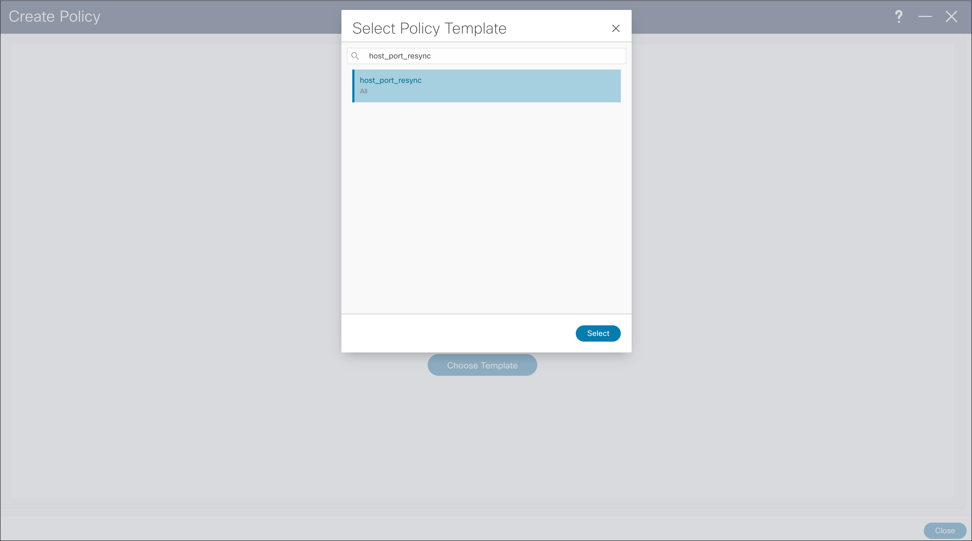
NDFC > LAN > Fabric > Policies > Action > Add Policies > Create Policy
NBM discovers an endpoint or host in one of these three ways:
● When the host sends an Address Resolution Protocol (ARP) request for its default gateway: the switch
● When the sender host sends a multicast flow
● When a receiver host sends an IGMP join message
● Host discovered via Address Resolution Protocol (ARP):
◦ Role: Is empty - nothing is displayed in this field
◦ NDFC displays the MAC address of the host
◦ NDFC displays the switch name and interface on the switch where the host is connected
● Host discovered by traffic transmission (source or sender)
◦ Role: Sender
◦ NDFC displays the multicast group, source IP address, switch name, and interface.
◦ If the interface is “empty”, see “fault reason”, which indicates the reason.
● Host discovered by IGMP report (receivers)
◦ Role: Dynamic, static, or external
◦ Dynamic receiver – receivers that send an IGMP report
◦ Static receiver – a receiver added using an API or “ip igmp static-oif” on the switch
◦ External receiver – a receiver outside the fabric
● NDFC displays the multicast group, source IP address, switch name, and interface.
● If the interface is “empty”, see the “fault reason”, which indicates the reason.
Figures 38 and 39 show the media controller topology and the discovered host results.
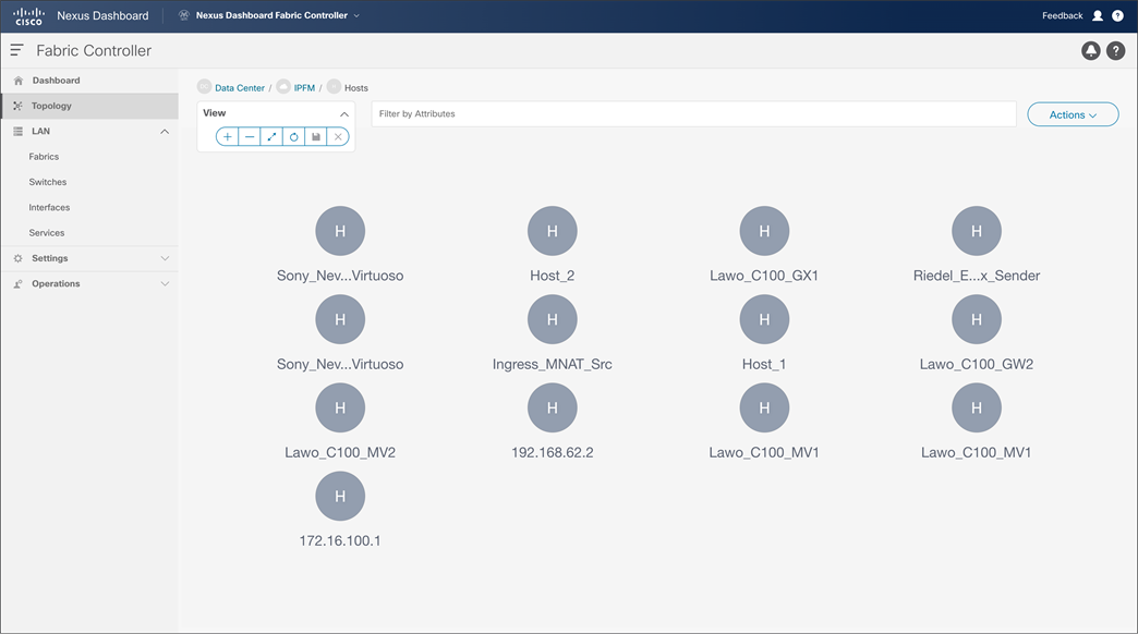
NDFC > Topology > Fabric > Hosts
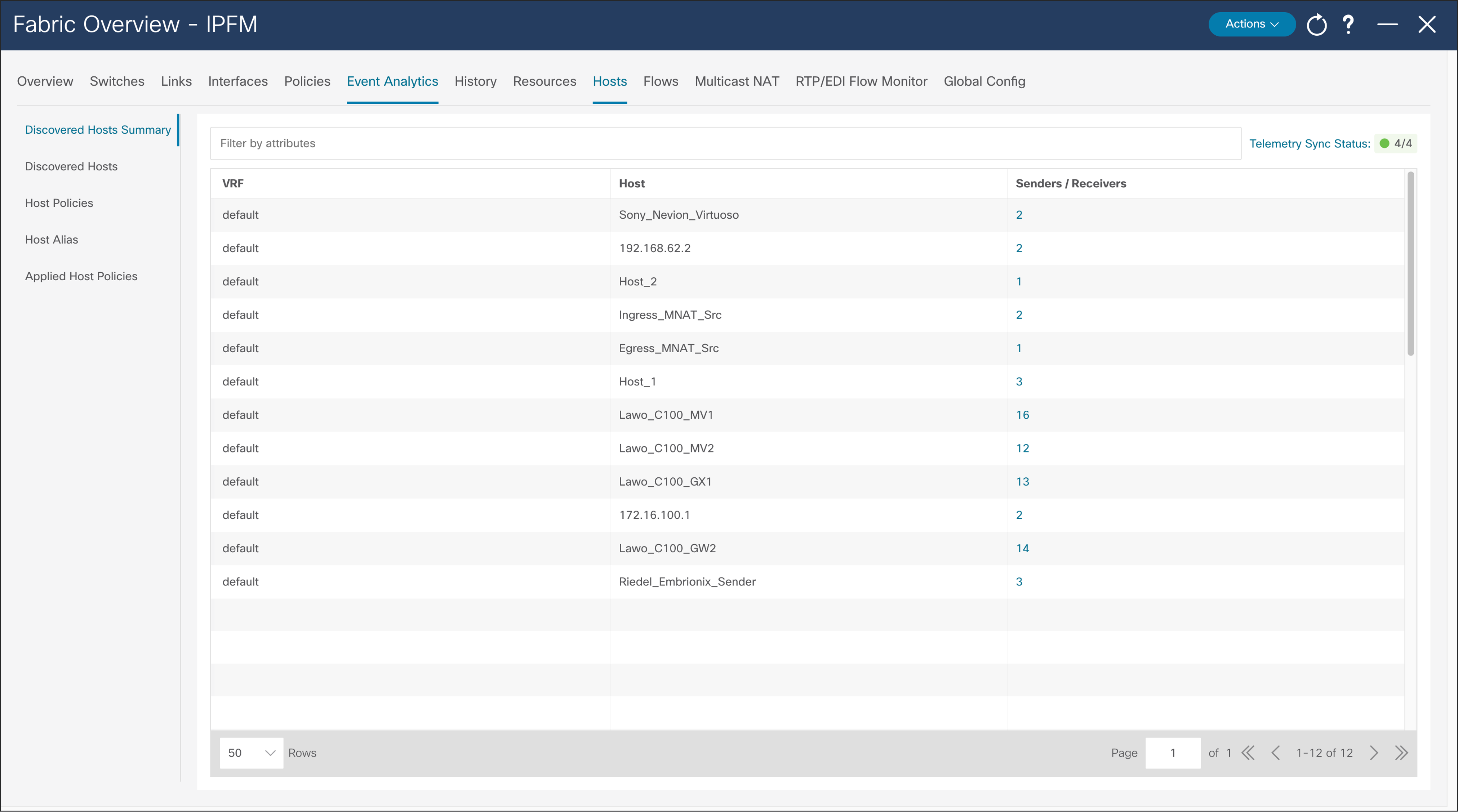
NDFC > Fabric > Fabric of choice > Hosts > Discovered Hosts Summary
A host alias is used to provide a meaningful name to an endpoint or host. The alias can be referenced in place of an IP address throughout the NDFC GUI (Figure 40).
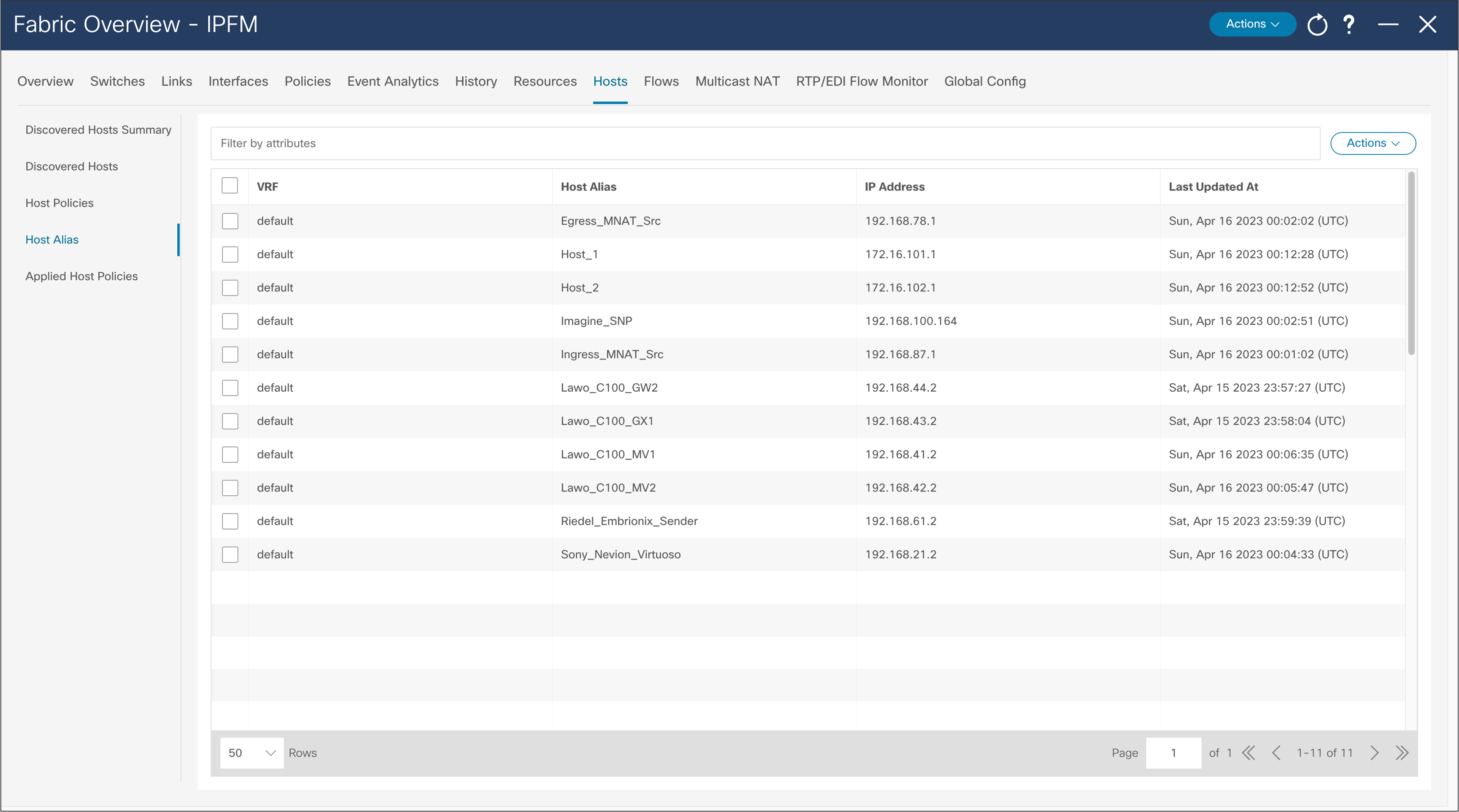
NDFC > Fabric > Hosts > Host Alias > Actions > Create Host Alias
The default host policy must be deployed before custom policies are configured. Default policy modification is permitted if not custom policies are deployed. Custom policies allow modification. Policies must be un-deployed before deleted (Figure 41).
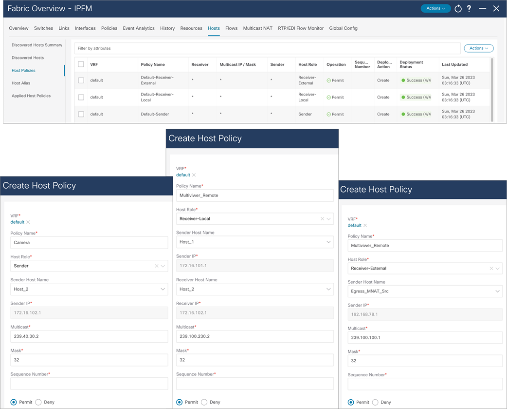
NDFC > Fabric > Fabric of choice > Hosts > Host Policies > Actions > Create Host Policy
Host policies created on NDFC are pushed to all switches in the fabric. The NBM process on the switch only applies relevant policies based on endpoints or hosts directly connected to the switch. Applied host policies provide visibility of where a given policy is applied – on which switch and which interface on the switch (Figure 42).
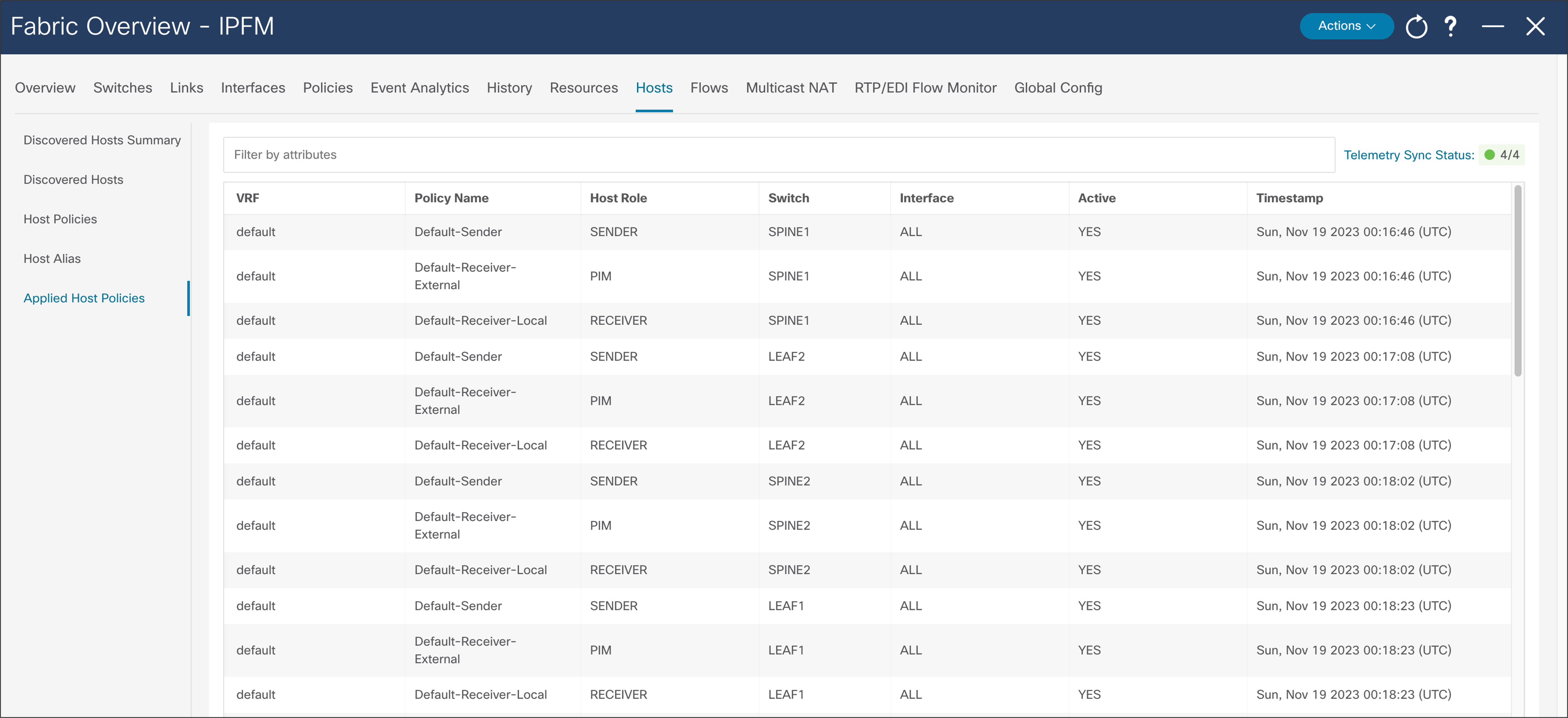
NDFC > Fabric > Fabric of choice > Hosts > Applied Host Policies
The default policy is set to 0 Gbps. The default policy must be deployed before any customer flow policy is configured and deployed. Flow policy modification is permitted, but the flows using the policy could be impacted during policy changes. Flow policy must be un-deployed before deleted (Figure 43).
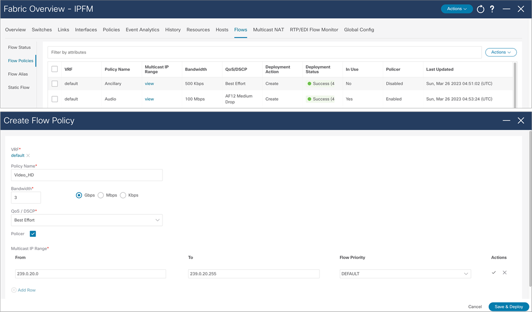
NDFC > Fabric > Fabric of choice > Flows > Flow policies
Operators can find it difficult to track applications using IP addresses. The flow alias provides the ability to provide a meaningful name to a multicast flow (Figure 44).
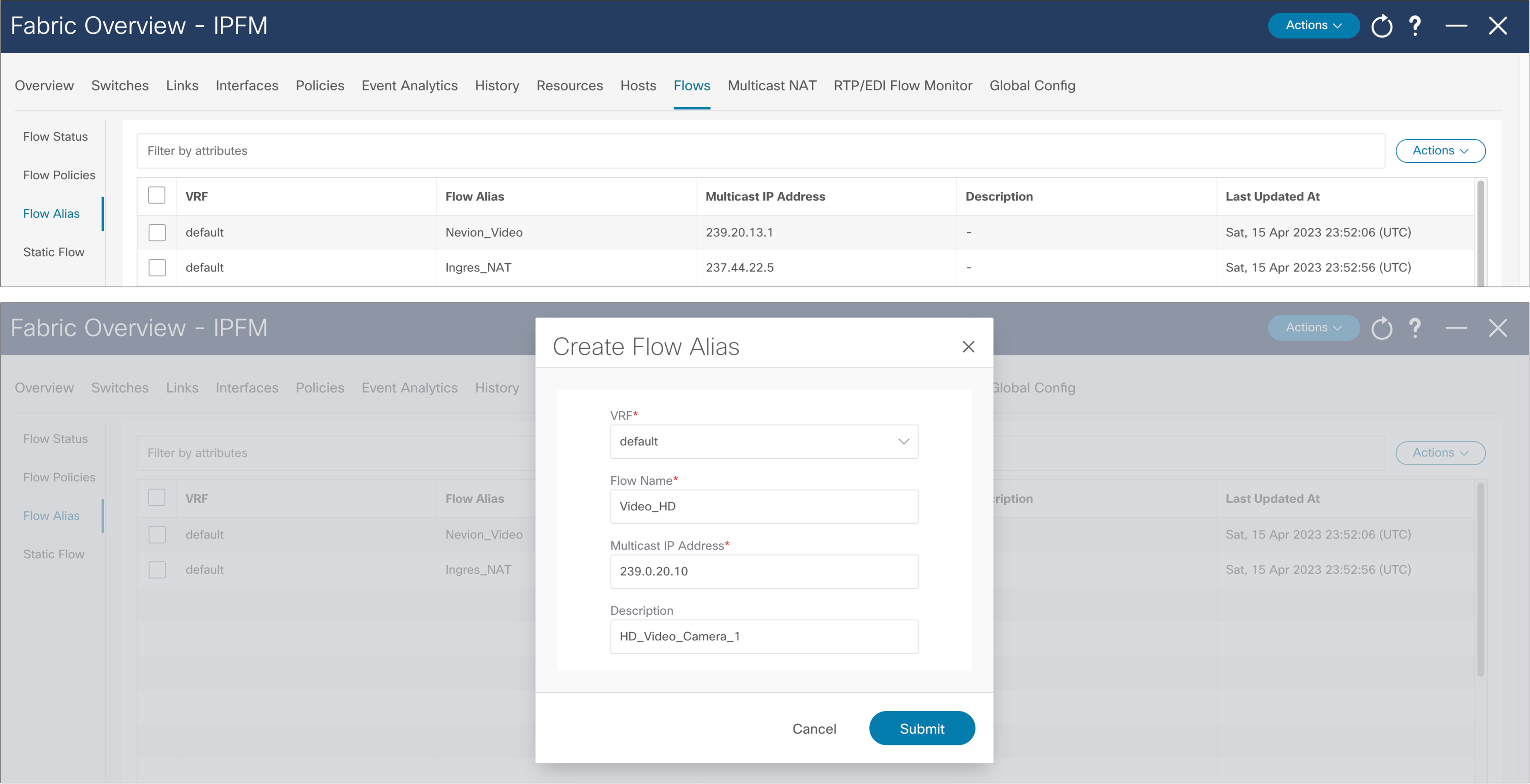
NDFC > Fabric > Fabric of choice > Flows > Flow Alias
Flow Visibility and Bandwidth Tracking
One of the broadcast industry’s biggest concerns in moving to IP was maintaining the capability to track the flow path. NDFC provides end-to-end flow visibility on a per-flow basis. The flow information can be queried from the NDFC GUI or through an API (see Figures 45 and 46).
One can view bandwidth utilization per link through the GUI or an API.
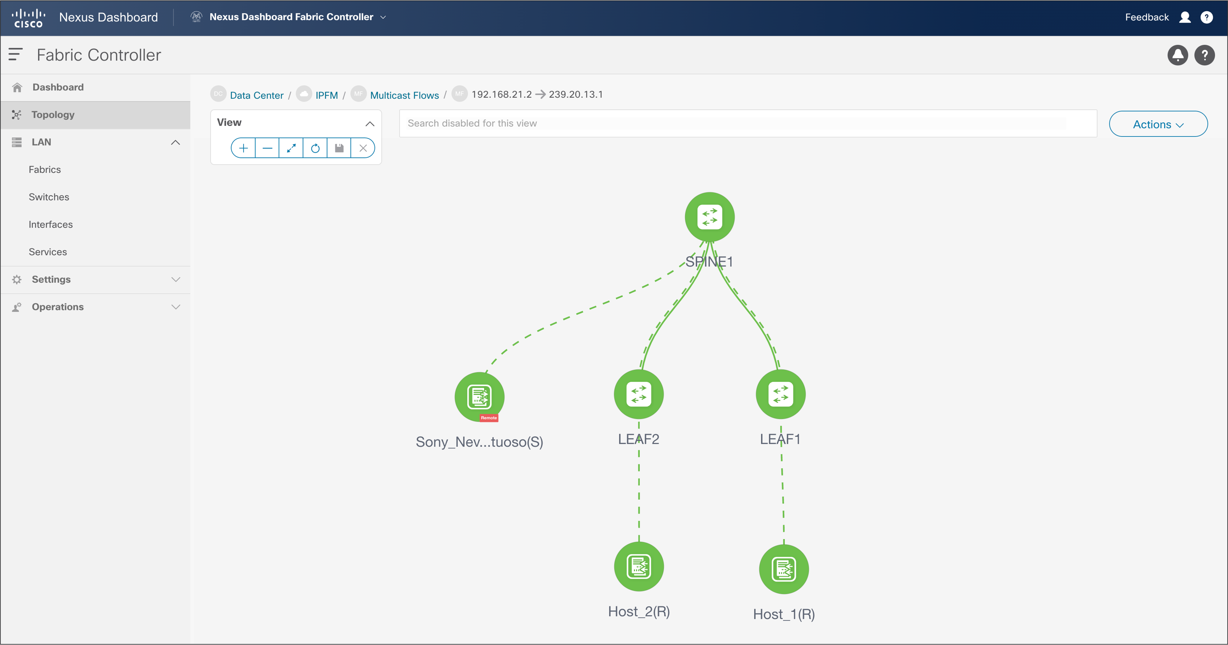
NDFC > LAN > Topology > Fabric > Multicast Flows
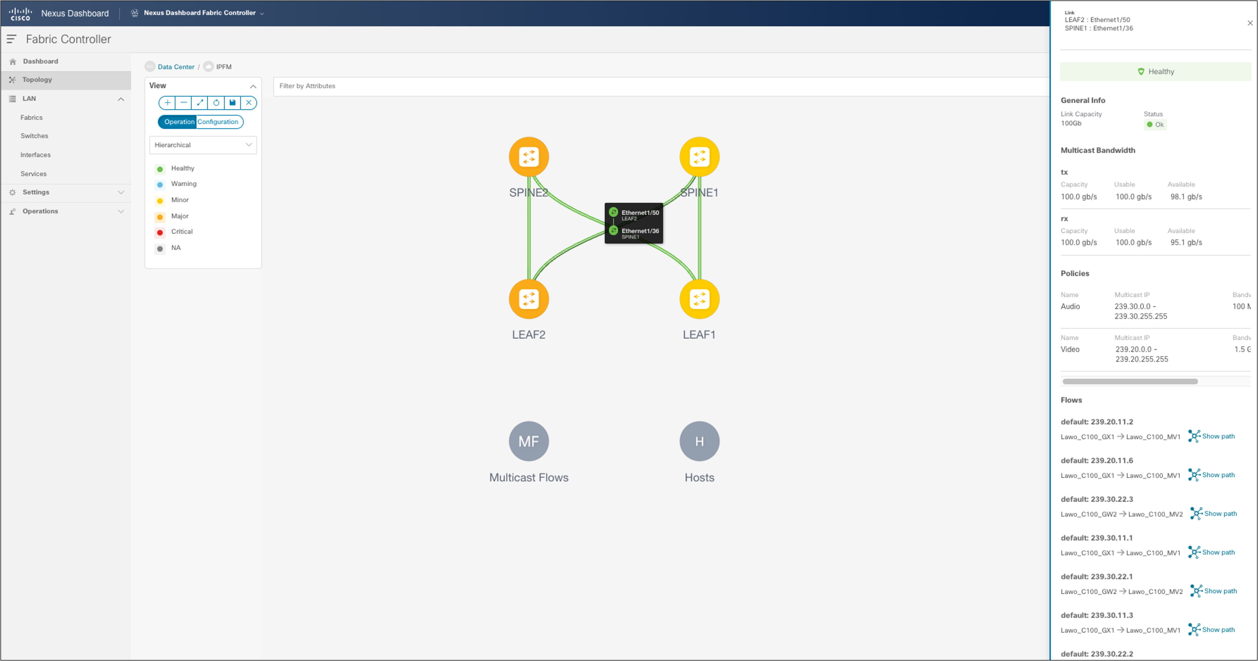
NDFC > Topology > Fabric of choice > Topology and double-click link
NDFC maintains a real-time per-flow rate monitor. It can provide the bit rate of flows in the system. If a flow exceeds the rate defined in the flow policy, the flow is policed, and the policed rate is also displayed. Flow information can be exported and stored for offline analysis (Figure 47).
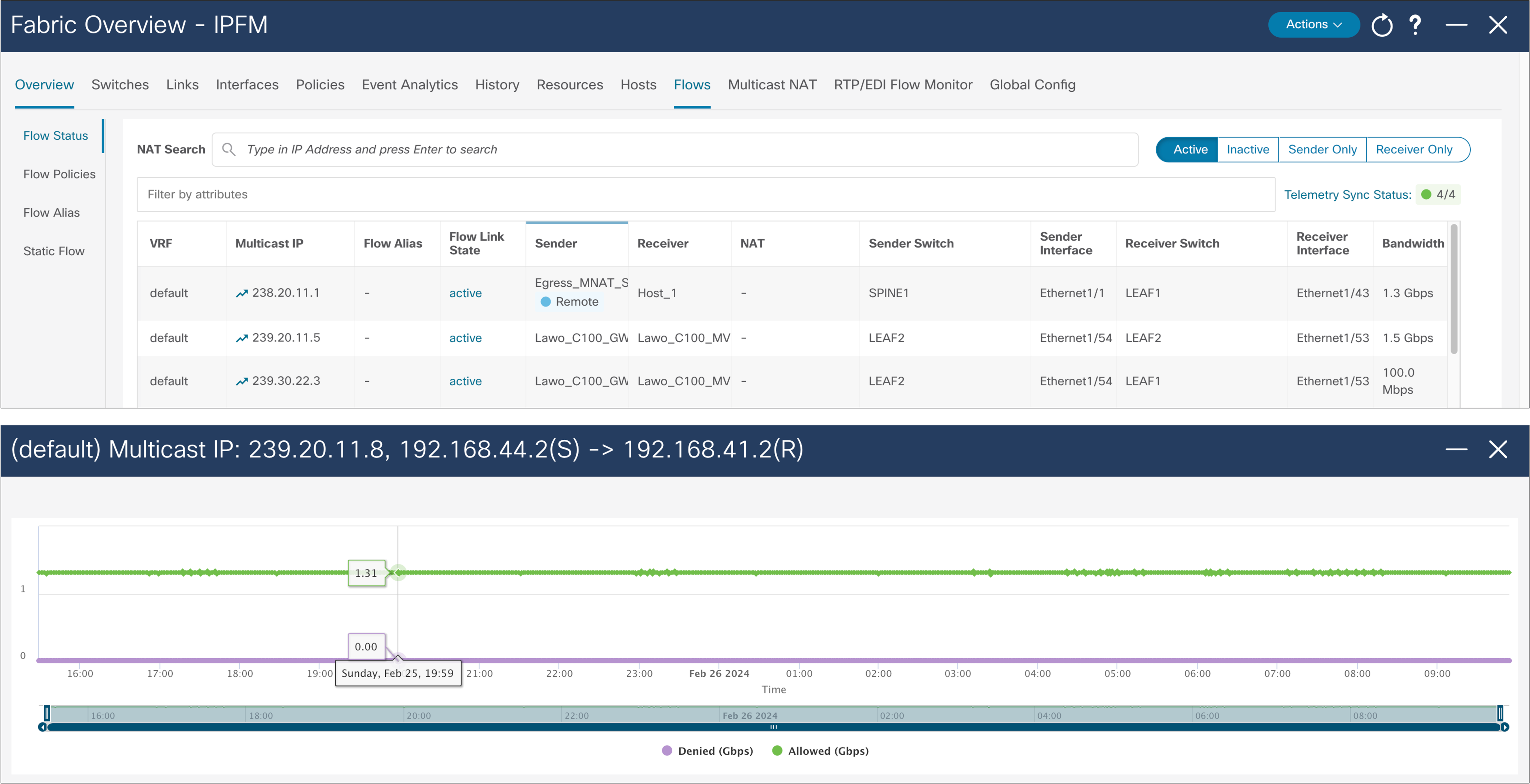
NDFC > LAN > Fabric > Fabric of choice > Flows > Flow Status
ASM Range and Unicast Bandwidth Reservation
ASM range and unicast bandwidth reservation can be configured and deployed from NDFC (Figure 48).
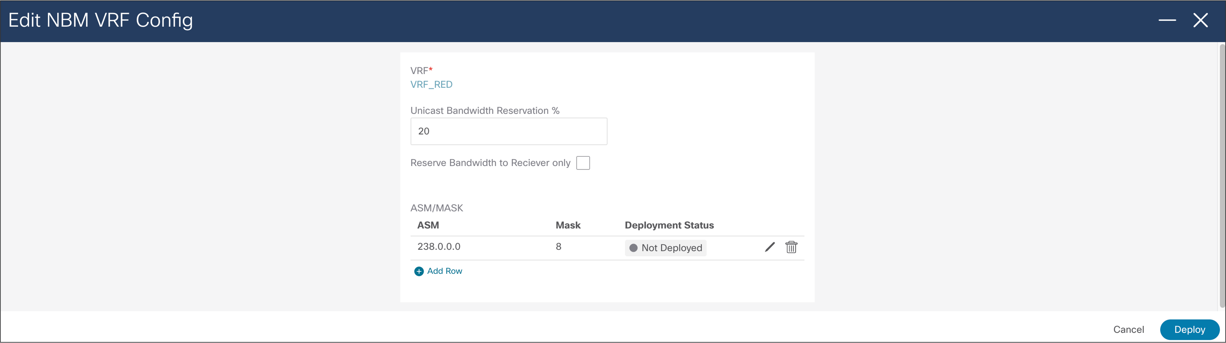
NDFC > LAN > Fabric > Switch Global Config > Action > Edit NBM VRF Config
External Link on a Border Leaf for Multi-Site
At the time when interface is configured as routed interface, user can select “IPFM external-link” option, to dedicate this interface as the external link configuration on a border leaf. This external link configuration can be done using NDFC (Figure 49).
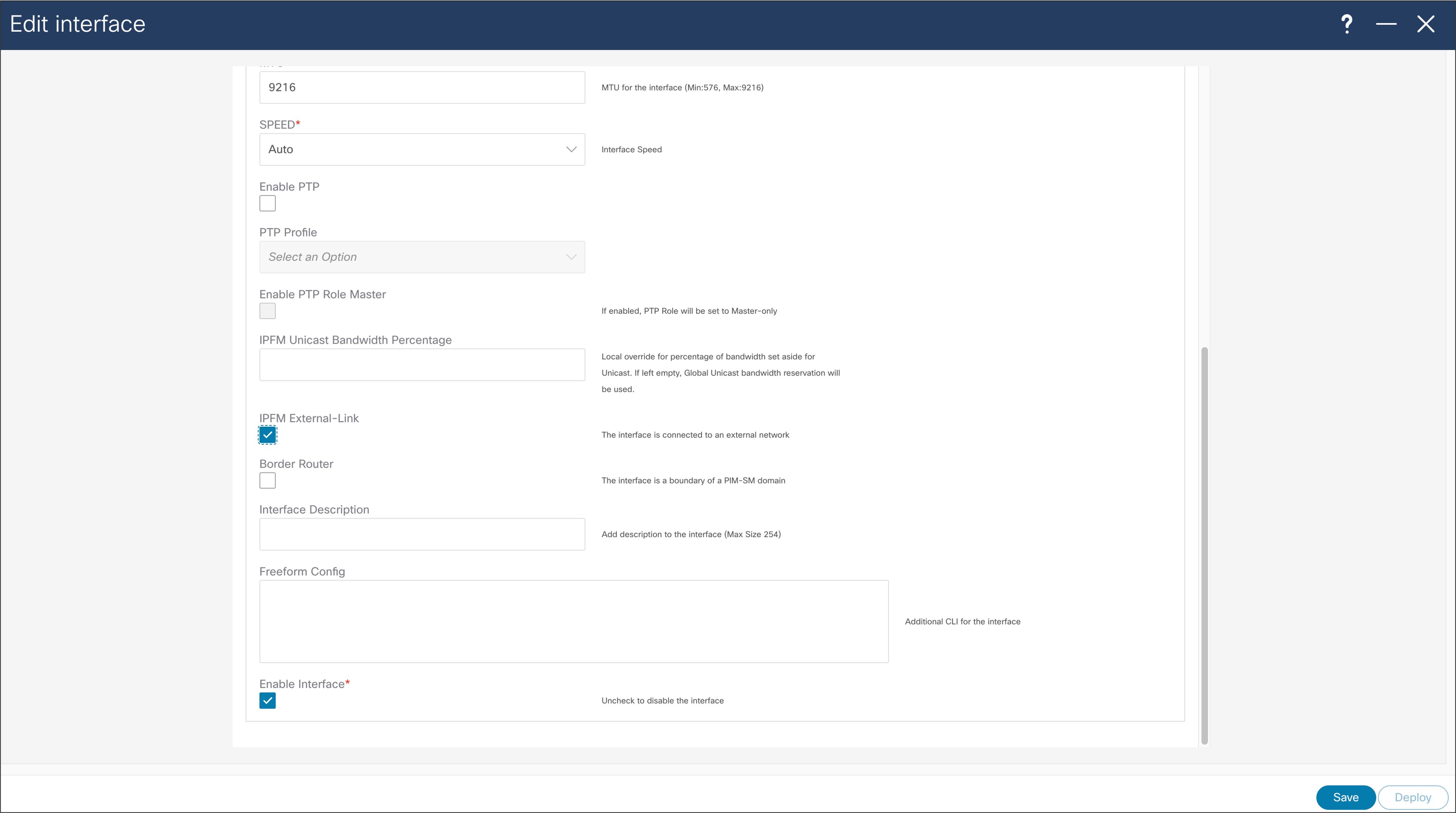
NDFC > LAN > Interface > Interface of choice > Edit > Policy > int_ipfm_l3_port
The NDFC for IPFM logs events that can be subscribed to using Kafka notifications. Activities that occur are logged, for example a new sender coming online, a link utilization, a new host policy pushed out, etc. Additional information about Kafka Notifications from NDFC can be found in Kafka Notifications for Cisco NDFC for IPFM Fabrics document.
NBM Policies Ownership with NDFC
NDFC in IPFM template, is used for provisioning of Host policies, Flow policies, ASM range, unicast bandwidth reservation, and NBM external links configurations, CLI must not be used. NDFC takes complete ownership of host policies, flow policies, ASM range, unicast bandwidth reservation, and NBM external links.
If a network was configured using command line interface (CLI), and imported in NDFC as part of Classic IPFM, when a switch is discovered, NDFC re-writes all policies, ASM range, unicast bandwidth reservation, and external links. The same happens when a switch reloads and comes back online; This is the default behavior of NDFC; it assumes all policy and global configuration ownership.
NDFC server properties for IP Fabric for Media can be accessed using the NDFC GUI. Navigate to server properties using NDFC > Settings > Server settings > IPFM tab.
The IPFM server properties in NDFC allow for the host polices that multicast address to be entered in form of prefix and mask. This option is disabled by default.
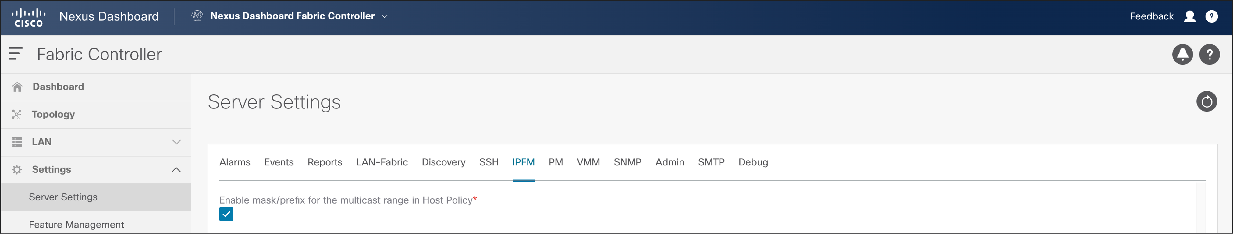
NDFC > Settings > Server Settings > IPFM
● By default, the host policy assumes a /32 mask for the multicast group IP address.
● Setting this option to “true” enables the use of a mask for the group with the user specifying a sequence number for each policy.
● All user-defined policies must be deleted and re-applied when this option is changed.
Precision Time Protocol (PTP) for Time Synchronization
Clock synchronization is extremely important in a broadcasting facility. All endpoints and IPGs that convert SDI to SMPTE 2110 IP stream must be time synchronized to ensure they are able to switch between signals, convert signals from IP back to SDI, etc. If the clocks are not in sync, it could result in lost samples in data and will cause audio splat or loss of video pixel.
PTP can be used to distribute the clock across the Ethernet fabric. PTP provides nanosecond accuracy and ensures all endpoints remain synchronized.
PTP works in a primary-secondary topology. In a typical PTP deployment, a PTP Grand Master (GM) is used as a reference. The GM is then connected to the network switch. The network switch can be configured to act as a PTP boundary clock or PTP transparent clock. In a boundary clock implementation, the switch thrives off the GM and acts as a primary for the devices connected to the switch. In transparent clock implementation, the switch simply corrects timing information in PTP to include the transit delay as the PTP packet traverses the switch. The PTP session is between the secondary and the GM (Figure 51).
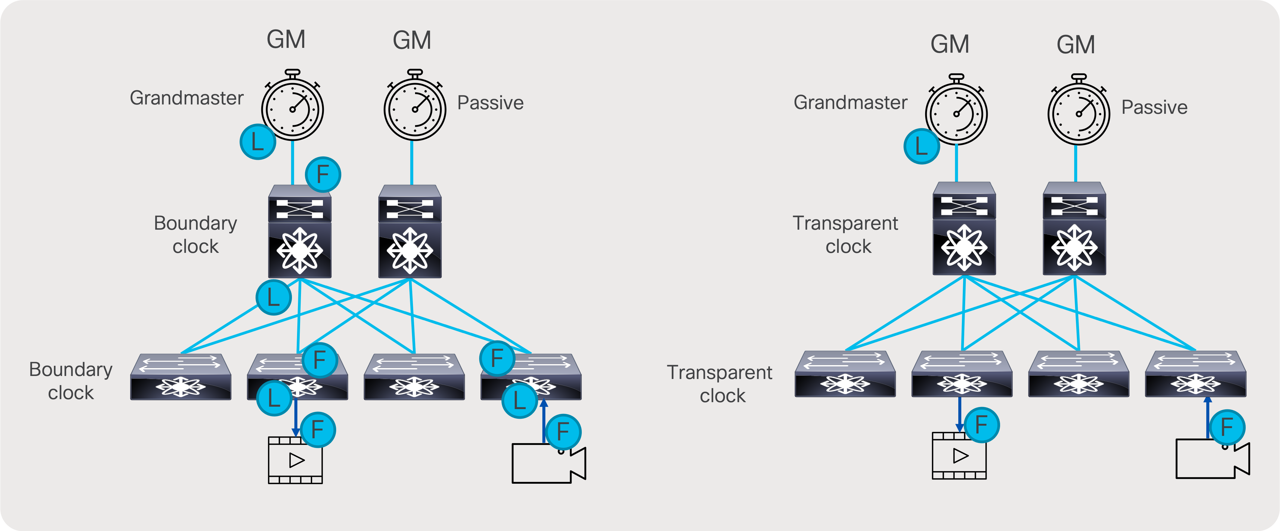
Transparent clock versus boundary clock
To be able to scale, the PTP boundary clock is the preferred implementation of PTP in an IP fabric. This distributes the overall load across all the network switches instead of putting all the load on the GM, which can only support a limited number of secondary.
It is always recommended to use two PTM GMs for redundancy. The same GM pair can be used to distribute the clock to a redundant fabric in a SMPTE 2022-7 type of deployment.
There are two PTP profiles utilized in the broadcasting industry: AES67 and SMPTE 2059-2. A Nexus switch acting as a boundary clock supports both the SMPTE 2059-2 and AES67 profile along with IEEE 1588v2.
Common rates that work across all profiles include:
● Sync interval -3 (0.125s or 8 packets per second)
● Announce interval 0 (1 per second)
● Delay request minimum interval -2 (0.25s or 4 per second)
Example:
feature ptp
PTP source IP address can be any IP address. If switch has a loopback, use the loopback IP as PTP source.
ptp source 1.1.1.1
interface Ethernet1/1
ptp
ptp delay-request minimum interval smpte-2059-2 -3
ptp announce interval smpte-2059-2 0
ptp sync interval smpte-2059-2 -3
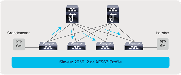
Grandmaster and passive clock connectivity
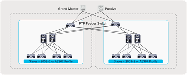
PTP implementation with a redundant network
For further details on designing PTP for Media Networks, refer to the PTP design guide.
To integrate PTP monitoring on NDFC, the following additions are needed to the telemetry configuration:
ptp notification type parent-change
ptp notification type gm-change
ptp notification type high-correction interval 30
ptp notification type port-state-change category all
telemetry
destination-group 200
ip address <ndfc_telemetry_ip> port 50051 protocol gRPC encoding GPB
sensor-group 300
data-source NX-API
path "show ptp brief"
path "show ptp parent"
sensor-group 302
data-source DME
path sys/ptp/correction depth unbounded
path sys/ptp/gmchange depth unbounded
path sys/ptp/parentchange depth unbounded
path sys/ptp query-condition query-target=subtree&target-subtree-class=ptpPtpPortState
subscription 300
dst-grp 200
snsr-grp 300 sample-interval 60000
snsr-grp 302 sample-interval 0
Advanced Capabilities of IP Fabric for Media
IP Fabric for Media Provides some advanced capabilities, where users can interconnect multiple fabrics, at different geographical locations, using multi-site solution. Furthermore, users can transport multicast and unicast (file based) flows over same fabric or divide fabric in multiple VRFs so it serves multiple users independent of each other. Network Address Translation, capabilities of Nexus 9000, enable user to fulfill use cases of contribution of overlapping IPs, distribution to a public cloud, and importing of streams to the IP fabric for media, and changing destination multicast address or converting unicast stream for distribution.
IPFM fabric, and Nexus 9000 devices, are capable of monitoring RTP flow sequence numbers, so it can detect missing packets in RTP stream.
Multi-Site and Remote Production – NBM Active
Multi-site is a feature that extends NBM across different IP fabrics. It enables reliable transport of flows across sites (Figure 54). An IP fabric enabled with PIM and NBM can connect to any other PIM-enabled fabric. The other fabric could have NBM enabled or could be any IP network that is configured with PIM only. This feature enables use cases such as remote production or connecting the production network with playout etc.
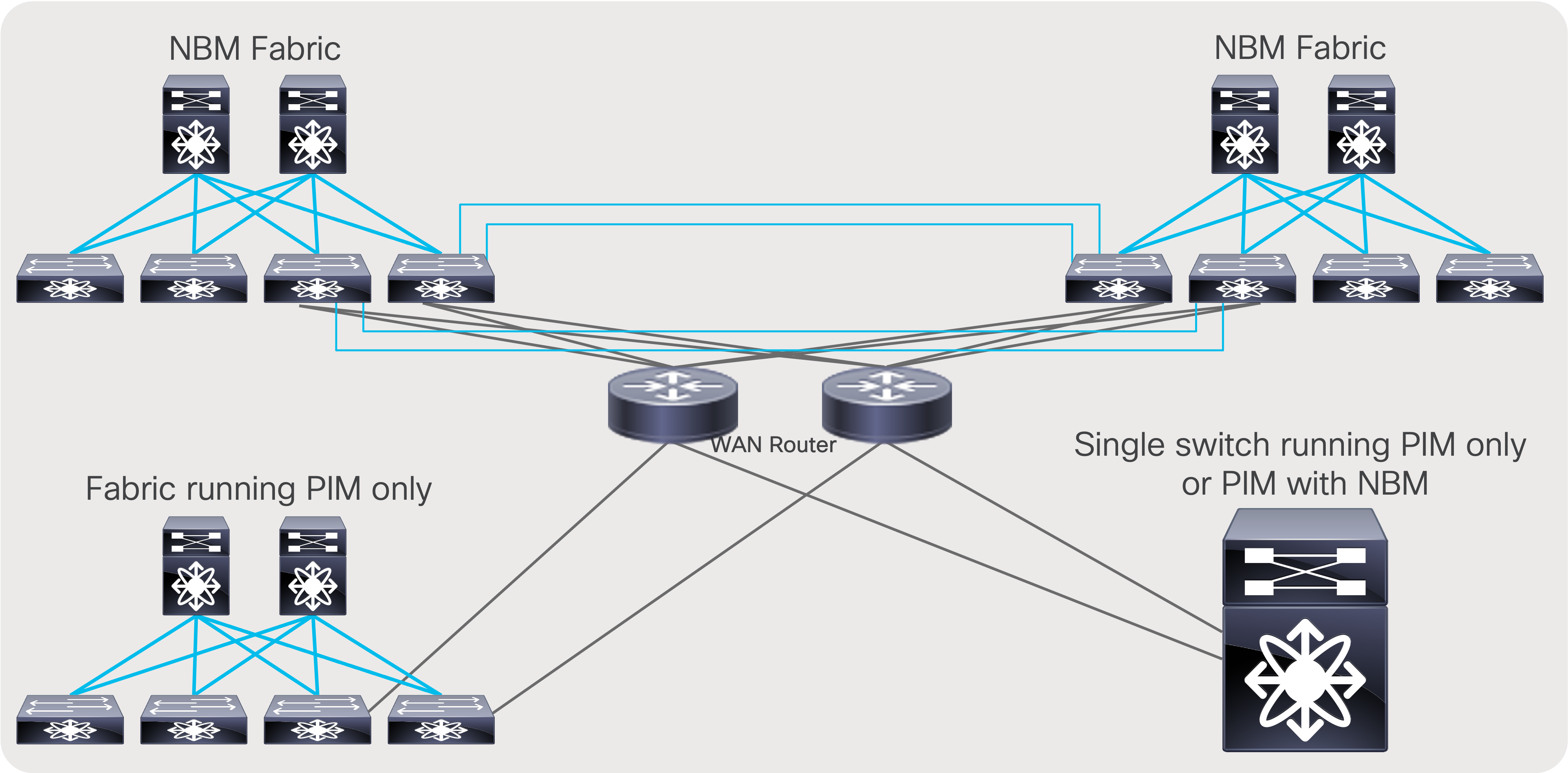
Multi-site network
For multi-site to function, unicast routing must be extended across the fabrics. Unicast routing provides source reachability information to PIM. When NBM is enabled on a fabric, the network switch that interconnects with external sites is enabled with the “nbm external-link” command on the WAN links (Figure 55). A fabric can have multiple border switches for redundancy and have multiple links on the border switches.
The other end of the link must have PIM enabled. If the other network is also enabled with NBM, then the “nbm external-link” CLI must be enabled. If it is a PIM network without NBM, no additional CLI needs to be configured. Simply enable PIM on the links. The border switches in the NBM fabric will form PIM adjacency with the external network device.
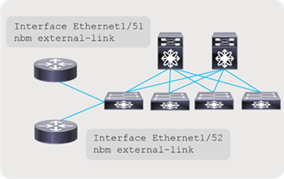
NBM external link
Multi-Site and NBM Active Host Policy (PIM policy)
To restrict what traffic can leave the fabric, NBM exposes PIM policy, and which one can enforce what multicast flows can exit the fabric. If the PIM or remote-receiver policy restricts a flow and the fabric gets a request for the flow setup on the external link, that request is denied. Furthermore, flow policy is enforced on external links, and for any incoming flows over external links, policer can be enforced based on a flow policy.
nbm host-policy
pim
default deny
!<seq_no.> source <local_source_ip> source <> group <multicast_group> permit|deny
default deny
100 source 192.168.1.1 group 239.1.1.1/32 permit
101 source 0.0.0.0 group 239.1.1.2/32 permit
102 source 0.0.0.0 group 230.0.0.0/8 permit
When all receivers use IGMPv3 and SSM, no additional configuration is needed to exchange flows between fabrics. However, when using PIM Any-Source Multicast (ASM) with IGMPv2, a full mesh MSDP session must be established between the RPs across the fabrics (Figure 56).
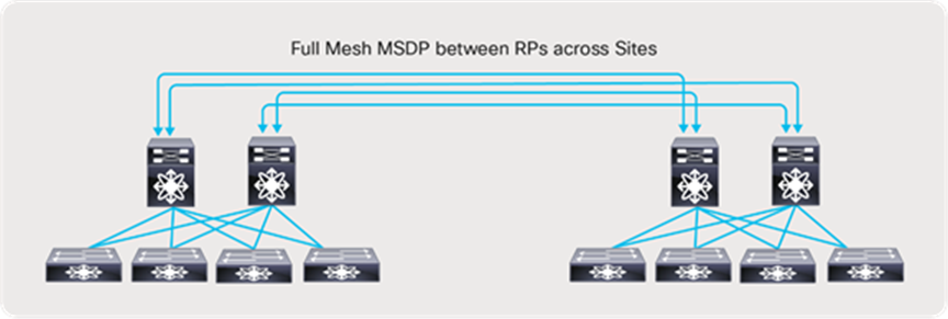
Multi-site and MSDP for any-source multicast (IGMPv2)
In case these sites are not directly connected as shown below (Figure 57), MSDP can be created between each site and the CORE, instead of full mesh across sites. Between the sites and the CORE, BGP must be used as the routing protocol. The BGP next hop and MSDP peering must use the same IP address. The reason BGP is required is that MSDP does an RPF check for the RP address originating the MSDP SA messages, and the unicast reachability to the RP must be learned over BGP. If each site runs an IGP like OSPF, then a mutual redistribution of routes between BGP and OSPF is needed to establish unicast route advertisement across the sites.
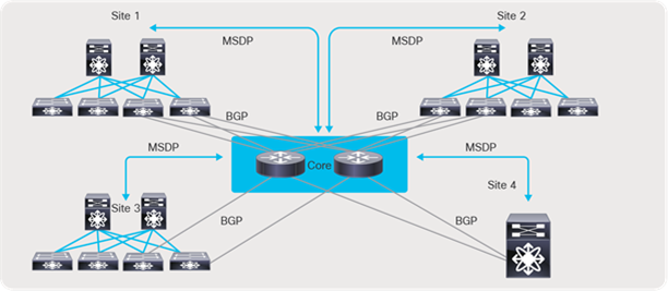
Multi-site and MDSP with CORE router type deployment
Sample configuration on the CORE
feature msdp
ip msdp peer 192.168.1.0 connected-source et1/54 remote-as 65001
router bgp 65005
neighbor 192.168.1.0 remote-as 65001
address-family ipv4 unicast
Sample configuration on border leaf
feature msdp
ip msdp peer 192.168.1.1 connected-source et1/49 remote-as 65005
router bgp 65001
neighbor 192.168.1.1 remote-as 65005
address-family ipv4 unicast
File (unicast) and Live (multicast) on the same IP Fabric
The flexibility of IP allows co-existence of file and live traffic on the same fabric. Using QoS, live traffic (multicast) is always prioritized over file-based workflows. When NBM active mode programs a multicast flow, it places the flow in a high-priority queue. Using user-defined QoS policies, live traffic can be placed in lower-priority queues. If there is a contention for bandwidth, the QoS configuration always ensures that live wins over file-based workflows.
NBM also allows reservation of a certain amount of bandwidth for unicast workflows in the fabric. By default, NBM assumes all bandwidth can be utilized for multicast traffic.
Use “nbm reserve unicast fabric bandwidth X”, a global Command-Line Interface (CLI) applied on a per VRF basis, to control bandwidth within fabric. To accommodate unicast traffic on a host interface that as well is under NBM bandwidth management, user can configure interface level unicast bandwidth reservation using “nbm bandwidth unicast X”, to reserve bandwidth for unicast traffic if needed.
When operating in NBM passive mode, the SDN controller is responsible for the unicast bandwidth, if any.
The following QoS policies must be applied on all switches to ensure multicast (live) is prioritized over unicast (file).
ip access-list ipfm-ucast
10 permit ip any 0.0.0.0 31.255.255.255
20 permit ip any 128.0.0.0 31.255.255.255
30 permit ip any 192.0.0.0 31.255.255.255
ip access-list ipfm-mcast
10 permit ip any 224.0.0.0/4
class-map type qos match-all ipfm-ucast
match access-group name ipfm-ucast
class-map type qos match-any ipfm-mcast
match access-group name ipfm-mcast
policy-map type qos ipfm-qos
class ipfm-ucast
set qos-group 0
class ipfm-mcast
set qos-group 7
interface ethernet 1/1-54
service-policy type qos input ipfm-qos
Using the concept of virtual routing and forwarding (VRF), network administrators can create multiple logical fabrics within the same physical network fabric. This is done by separating physical interfaces into different VRFs. An example of such deployment may include creating a 2022-7 network on the same physical topology (Figure 58) or running NBM in one VRF and non-NBM multicast in another. Lastly, a deployment model of NBM mode pim-active in a VRF and NBM mode pim-passive in another VRF is also possible (refer to the software release notes for the supported release).
Before you associate an NBM VRF, create the VRF routing context (using the VRF context vrf-name command) and complete the unicast routing and PIM configurations.
nbm vrf vrf-name
nbm mode pim-active|pim-passive
Creating a 2022-7 type deployment using VRF
Network Address Translation and NBM
Network Address Translation – NAT, allows network devices to translate Source IP address, Destination IP address, or Layer 4 ports of the IP packets so reflect new information, and packet will be forwarded based on it. Unicast NAT is used to translate source and/or destination IP address, and Layer 4 port information on the boundary between private and public networks so it would hide private network information and enable routing on the public internet. Multicast NAT address translation, primary translates destination IP address from one to another multicast destination IP, usual use case is overlap in Multicast destination IP between two networks.
Nexus 9000 switches provide capabilities of NAT, for unicast and multicast address translation. Furthermore, Nexus 9000 switches enable translation between Unicast and Multicast and Multicast to Unicast, that allows to address additional use cases, connecting to public cloud, or content delivery.
Multicast Network Address Translation allows translation of multicast destination IP address. Multicast NAT translates (S1,G1) entries, in to (S2,G2), to accommodate packet incoming with overlapping addresses, or addresses that are not expected by the application.
Multicast NAT on Nexus 9000 series of switches is represented by Multicast Service Reflection feature, provides ingress translation, for flow incoming on an interface for their (S1,G1) to be translated to new entries, in to (S2,G2). Furthermore, service reflection can allow egress translation, where (S1,G1) can be translated to (S2,G2) at the outgoing interface.
Ingress multicast NAT, or ingress service reflection allows for (S1,G1) that are originated at contribution site (Stadium) to be imported in the production, where same (S1,G1) already exists. Ingress Multicast NAT will translate contribution (S1,G1) to (S2,G2) at the incoming interface of the incoming device in the studio, where this stream will be propagated through the network as new (S2,G2) to receivers.

Ingress Multicast Network Address Translation
Nexus 9000 devices support Ingress Multicast NAT, that allows one to one mapping between originating multicast group to translated multicast group. Incoming stream will be translated based on the configured rule. Below is example of configuring ingress multicast NAT.
Note: Carving out TCAM for Multicast NAT is mandatory.
hardware access-list tcam region mcast-nat 512
Create loopback interface that will be used as source IP address for translated packets.
interface loopback1
ip address 192.168.37.100/24
ip router ospf 1 area 0.0.0.0
ip pim sparse-mode
Sample configuration for Ingress Multicast NAT
ip service-reflect source-interface loopback1
ip service-reflect mode ingress 239.0.0.0/24
ip service-reflect destination 239.0.0.10 to 237.0.10.10 mask-len 32 source 192.168.23.10 to 192.168.37.10 mask-len 32
For distribution use case, egress multicast NAT can translate (S1,G1) to multiple streams so they can be distributed to different users without disclosing original (S1,G1). Egress Multicast NAT takes presence of the egress interface of the switch and allows many to one translation. (S1,G1) to (S2,G2),(S3,G3), and (S4,G4).
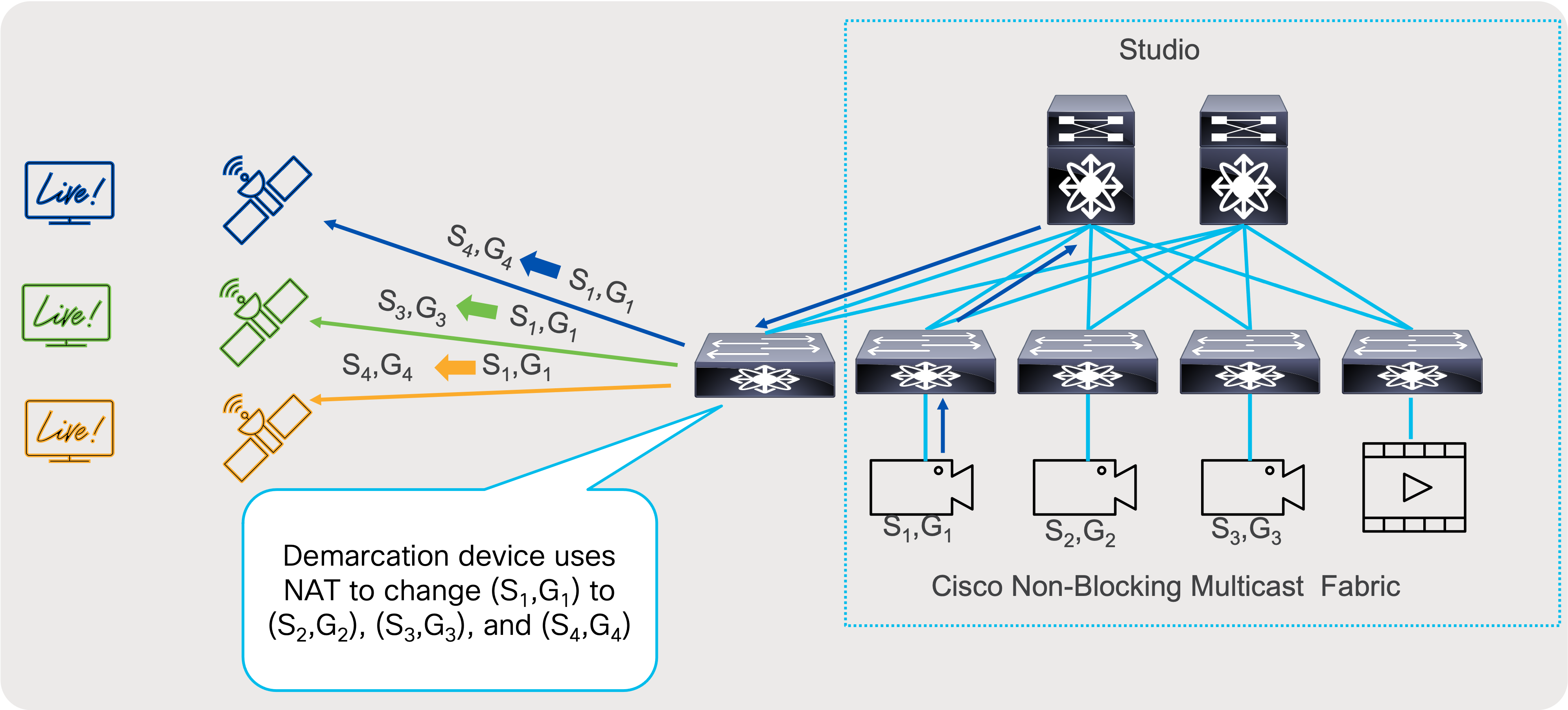
Egress Multicast Network Address Translation
Nexus 9000 switches allow one to many translations with Egress Multicast NAT, where originating multicast group, can be translated to multiple destination, so each distribution can receive unique set of multicast groups, so original group is hidden. This is welcome at demarcation point, where streams can be sent out.
Following is the sample of Multicast Egress NAT configuration:
Note: Carving out TCAM for multicast NAT is mandatory.
hardware access-list tcam region mcast-nat 512
Create loopback interface that will be used as source IP address for translated packets.
interface loopback1
ip address 192.168.37.100/24
ip router ospf 1 area 0.0.0.0
ip pim sparse-mode
ip igmp static-oif 239.0.0.10
Sample configuration for Egress Multicast NAT
ip service-reflect source-interface loopback1
ip service-reflect mode egress 239.0.0.0/24
ip service-reflect destination 239.0.0.10 to 237.0.10.10 mask-len 32 source 192.168.23.10 to 192.168.37.10 mask-len 32 static-oif Ethernet1/27
multicast service-reflect interface all map interface Ethernet1/54 max-replication 3
System will create service interface, with set of sub-interfaces needed for egress multicast NAT.
interface Ethernet1/54
description Auto-configured by multicast service-reflect map CLI. Do not edit
link loopback
ip forward
no shutdown
interface Ethernet1/54.1
description Auto-configured by multicast service-reflect map CLI. Do not edit
encapsulation dot1q 11
no shutdown
interface Ethernet1/54.2
description Auto-configured by multicast service-reflect map CLI. Do not edit
encapsulation dot1q 12
no shutdown
interface Ethernet1/54.3
description Auto-configured by multicast service-reflect map CLI. Do not edit
encapsulation dot1q 13
no shutdown
interface Ethernet1/54.100
description Auto-configured by multicast service-reflect map CLI. Do not edit
encapsulation dot1q 110
ip forward
ip pim sparse-mode
no shutdown
For distribution use case to public cloud where multicast traffic over the internet is not allowed, egress multicast to unicast NAT can translate (S1,G1) to unicast stream (US2,UD2), where UD2 represent unicast destination, reachable over public internet or over VPN. This way, transfer of multicast information can be accomplished even if multicast transport is not allowed in the public network.
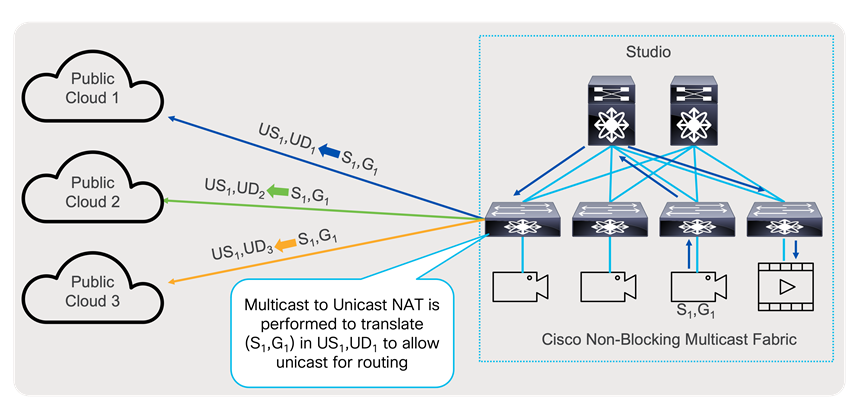
Multicast to Unicast Network Address Translation
Multicast to Unicast NAT, uses same principles as Egress Multicast NAT, it can perform one too many translations. In addition, that multicast stream (S1,G1) can continue to be transported as multicast stream and be translated at the same time. Furthermore, Egress Multicast NAT and Multicast to Unicast NAT can be performed at the same time.
Following is example of configuration of Multicast to Unicast NAT on Nexus 9000 switches:
Note: Carving out TCAM for multicast NAT is mandatory.
hardware access-list tcam region mcast-nat 512
Create loopback interface that will be used as source IP address for translated packets.
interface loopback1
ip address 192.168.37.100/24
ip router ospf 1 area 0.0.0.0
ip pim sparse-mode
ip igmp static-oif 239.0.0.10
Sample configuration for Multicast to Unicast NAT
ip service-reflect source-interface loopback1
ip service-reflect mode egress 239.0.0.0/24
ip service-reflect destination 239.0.0.10 to 192.168.0.10 mask-len 32 source 192.168.23.10 to 192.168.37.10 mask-len 32
multicast service-reflect dest-prefix 0.0.0.0/0 map interface Ethernet1/54 max-replication 3
System will create service interface, with set of sub-interfaces needed for multicast to unicast NAT.
interface Ethernet1/54
description Auto-configured by multicast service-reflect map CLI. Do not edit
mtu 9216
link loopback
ip forward
no shutdown
interface Ethernet1/54.1
description Auto-configured by multicast service-reflect map CLI. Do not edit
mtu 9216
encapsulation dot1q 11
no shutdown
interface Ethernet1/54.2
description Auto-configured by multicast service-reflect map CLI. Do not edit
mtu 9216
encapsulation dot1q 12
no shutdown
interface Ethernet1/54.3
description Auto-configured by multicast service-reflect map CLI. Do not edit
mtu 9216
encapsulation dot1q 13
no shutdown
interface Ethernet1/54.100
description Auto-configured by multicast service-reflect map CLI. Do not edit
mtu 9216
encapsulation dot1q 110
ip forward
ip pim sparse-mode
no shutdown
For unicast traffic to be routed, ip route needs to exist to destination. A static route can accommodate this.
ip route 192.168.0.0/24 192.168.27.10
When source of signal is in public cloud and or video that is produced as unicast stream, can be imported for decoding, and converted to multicast stream, to be forwarded and replicated to multiple hosts in most efficient way, instead sending multiple unicast streams, over public internet. Unicast to Multicast NAT can translate (US1,UD1) to (S1,G1).
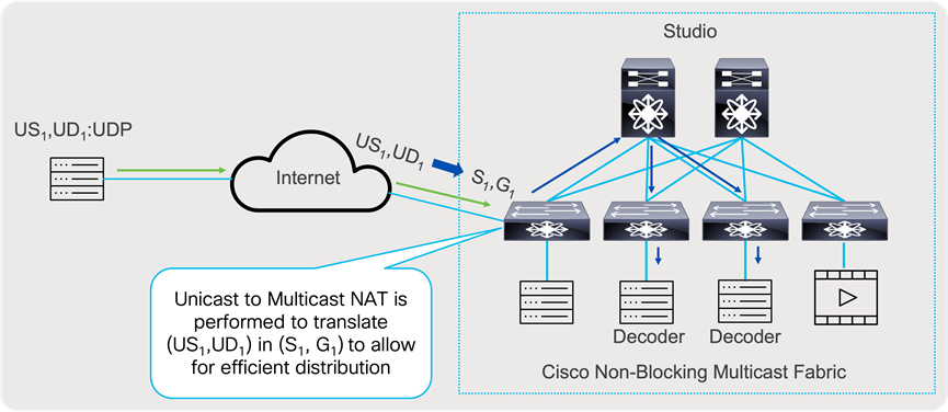
Unicast to Multicast Network Address Translation
Nexus 9000 devices support Unicast to Multicast NAT, and it is done in ingress direction, that allows one to one mapping between originating unicast stream to translated multicast group. Incoming stream will be translated based on the configured rule.
Below is example of configuring ingress multicast NAT.
Note: Carving out TCAM for multicast NAT is mandatory.
hardware access-list tcam region mcast-nat 512
Create loopback interface that will be used as destination for unicast flows, and as source IP address for translated packets.
interface loopback1
ip address 192.168.37.100/24
ip address 192.168.28.10/24 secondary
ip router ospf 1 area 0.0.0.0
ip pim sparse-mode
Sample configuration for Unicast to Multicast NAT
ip service-reflect source-interface loopback1
ip service-reflect destination 192.168.28.10 to 237.0.10.10 mask-len 32 source 192.168.23.10 to 192.168.37.10 mask-len 32
multicast service-reflect dest-prefix 0.0.0.0/0 map interface Ethernet1/54 max-replication 3
System will create service interface, with set of sub-interface needed for unicast to multicast NAT.
interface Ethernet1/54
description Auto-configured by multicast service-reflect map CLI. Do not edit
mtu 9216
link loopback
ip forward
no shutdown
interface Ethernet1/54.1
description Auto-configured by multicast service-reflect map CLI. Do not edit
mtu 9216
encapsulation dot1q 11
no shutdown
interface Ethernet1/54.2
description Auto-configured by multicast service-reflect map CLI. Do not edit
mtu 9216
encapsulation dot1q 12
no shutdown
interface Ethernet1/54.3
description Auto-configured by multicast service-reflect map CLI. Do not edit
mtu 9216
encapsulation dot1q 13
no shutdown
interface Ethernet1/54.100
description Auto-configured by multicast service-reflect map CLI. Do not edit
mtu 9216
encapsulation dot1q 110
ip forward
ip pim sparse-mode
no shutdown
Media Flow Analytics with RTP Flow Monitoring
To simplify detection of packet loss on an RTP or EDI flow, including both compressed and uncompressed media, the Cisco Nexus 9000 family of switches FX/FXP/FX2/FX3/GX/GX2A/GX2B can perform deep packet inspection and trigger a notification when traffic loss is detected. The detection on the switch can be streamed to NDFC using telemetry. Details on this feature and how to configure it can be found in the Media Flow Analytics white paper.
The configuration given below is needed on the Cisco Nexus 9000 switch to stream RTP/EDI flow monitoring to NDFC, or by selecting RTP monitoring in telemetry policy configuration in NDFC fabric, displayed at Figure 35.
telemetry
destination-group 200
ip address <ndfc_telemetry_ip> port 50051 protocol gRPC encoding GPB
sensor-group 500
data-source NX-API
path "show flow rtp details"
path "show flow rtp errors active"
path "show flow rtp errors history"
subscription 500
dst-grp 200
snsr-grp 500 sample-interval 30000
Sub-interface allows logical separation on a physical parent interface in multiple logical interfaces, where each logical interface can take unique Layer 3 personality. Separating in logical interfaces allows one network to interconnect to a different network and still allow logical separation of traffic by carrying VLAN tag.
Use case where user connects a network to service provider that requires traffic to be VLAN tagged, for per customer segmentation. To accommodate appropriate bandwidth management for media flow transport, NBM brings bandwidth awareness to a sub interface level.
NBM allows parent interface to conations 100% of Bandwidth for multicast by default, and at the time of creation sub-interfaces do not have any bandwidth allocated to them. To allocate bandwidth to a sub-interface, the user must reduce bandwidth allocated to parent switch, and distribute bandwidth to a sub-interface. Sum of all bandwidths of parent and all associated sub-interface cannot exceed 100%. Users may also allocate some bandwidth to unicast traffic.
In the example below parent interface have, two sub-interfaces configured, and they have split 100% of interface bandwidth, to 80% to parent and 10% to each of sub interface:
interface Ethernet1/1
nbm bandwidth capacity 80
interface Ethernet1/1.10
nbm bandwidth capacity 10
interface Ethernet1/1.11
nbm bandwidth capacity 10
If this is 100Gbps interface, this means that the parent switch could accommodate 80Gbps of multicast traffic, where each sub-interface could accommodate up to 10Gbps of multicast traffic.
Sub-interfaces as well can accommodate forwarding of unicast traffic, by allocation from the bandwidth already allocated to that interface. Following the previous example, a sub-interface has allocated 50% of bandwidth to unicast traffic. Following previous example, sub interface Ethernet 1/1.10, out of 10Gbps that were allocated to traffic, 5Gbps can be used for unicasting and 5Gbps are allocated for multicast.
interface Ethernet1/1
nbm bandwidth capacity 80
interface Ethernet1/1.10
nbm bandwidth capacity 10
nbm bandwidth unicast 50
interface Ethernet1/1.11
nbm bandwidth capacity 10
To verify what is interface allocation of bandwidth user can execute command “show nbm interface bandwidth interface e1/1.10”.
Integration between the Broadcast Controller and the Network
The IP network is only a part of the entire solution. The broadcast controller is another important component responsible for the facility's overall functioning. With IP deployments, the broadcast controller can interface with the IP fabric to push host and flow policies as well as other NBM configurations such as ASM range, unicast bandwidth reservation, and external link. The broadcast controller does this by interfacing with NDFC or by directly interfacing with the network switch using a network API exposed by the Nexus Operating System (OS). The broadcast controller can also subscribe to notifications from the network layer and present the information to the operator.
The integration between the broadcast controller and the network helps simplify day-to-day operations and provides a complete view of the endpoint and the network in a single pane of glass.
Deployments in which there is no integration between the broadcast controller and network are also supported and provide complete functionality. In such deployments, the NBM polices, and configuration are directly provided to the NDFC GUI or the switch CLI. In addition, both NDFC and NX-OS on the switch expose APIs that enable policy and configuration provisioning using scripts or any other automation.
For a list of NDFC APIs, visit https://developer.cisco.com/docs/nexus-dashboard-fabric-controller/latest/#!api-reference-lan.
For a list of NBM APIs (IP Fabric for Media), visit https://developer.cisco.com/site/nxapi-dme-model-reference-api/.
The control network can be divided into two segments. One segment is the fabric control network, which includes the network between the IP fabric and the NDFC running on Nexus Dashboard Cluster. The other network is the endpoint control network, which enables the broadcast controller to communicate with the endpoints and the NDFC.
Figure 63 shows the logical network connectivity between the broadcast controller, endpoints, and NDFC.
The control network typically carries unicast control traffic between controllers and endpoints.
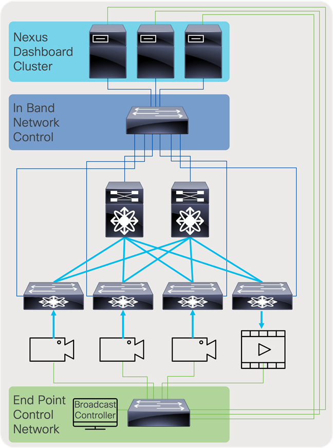
Control network
The solution offers flexible and scalable spine and leaf deployment in addition to using a single modular chassis deployment. IP provides a lot of flexibility and the ability to move flows across studios that could be geographically distributed. It enables the move to Ultra-HD (UHD) and beyond, the use of the same fabric for various media workflows, and other use cases such as resource sharing, remote production, etc.
OBVAN: Deploying an IP fabric inside an Outside Broadcast Production Truck
OBVANs are mini-studio and production rooms inside a truck that cover live events such as sports, concerts, etc. Given different events are covered in different formats, one may be HD and another UHD, and at every event location the endpoints are cabled and then moved. The truck requires operational simplicity and a dynamic infrastructure. A single modular switch, such as a Cisco Nexus 9508-R or 9504-R switch, is suitable for a truck (Figure 64).
OBVAN deployment
A studio deployment requires an infrastructure that is flexible and scalable. With SDI, several cables must be stretched across long distances, making the infrastructure rigid. With IP, a single modular chassis can be used, however, the challenges associated with stretching multiple cables to the switch still exist. To support flexibility, studio designs are often deployed using a spine-and-leaf architecture. With this architecture, the leaf can be placed at every studio location and then a single or couple of 100-Gb fibers are connected from the leaf to the spine. This model is similar to how a typical IT infrastructure is designed. The flexibility and ability to move any flow across any links enables sharing resources. This means a few production control rooms can be used to control multiple studios at different times. The primary control room can also be connected to the same fabric. The spine-and-leaf mode can also scale, so that if new studios are deployed, a leaf switch can simply be added to serve that facility (Figure 65).
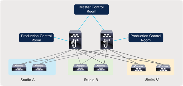
Flexible spine-and-leaf studio deployment
Remote Production and Multi-Site
IP simplifies transport of flows across sites and locations. This enables remote production, a use case where a production room is in the main site, producing an event that is being recorded in a remote site. This can be accomplished by interconnecting the remote leaf to the central location using a service provider link. The same architecture can also be used to interconnect an Outside Broadcasting (OB) truck to a studio and move flows from the OB truck to the studio (Figures 66 and 67).
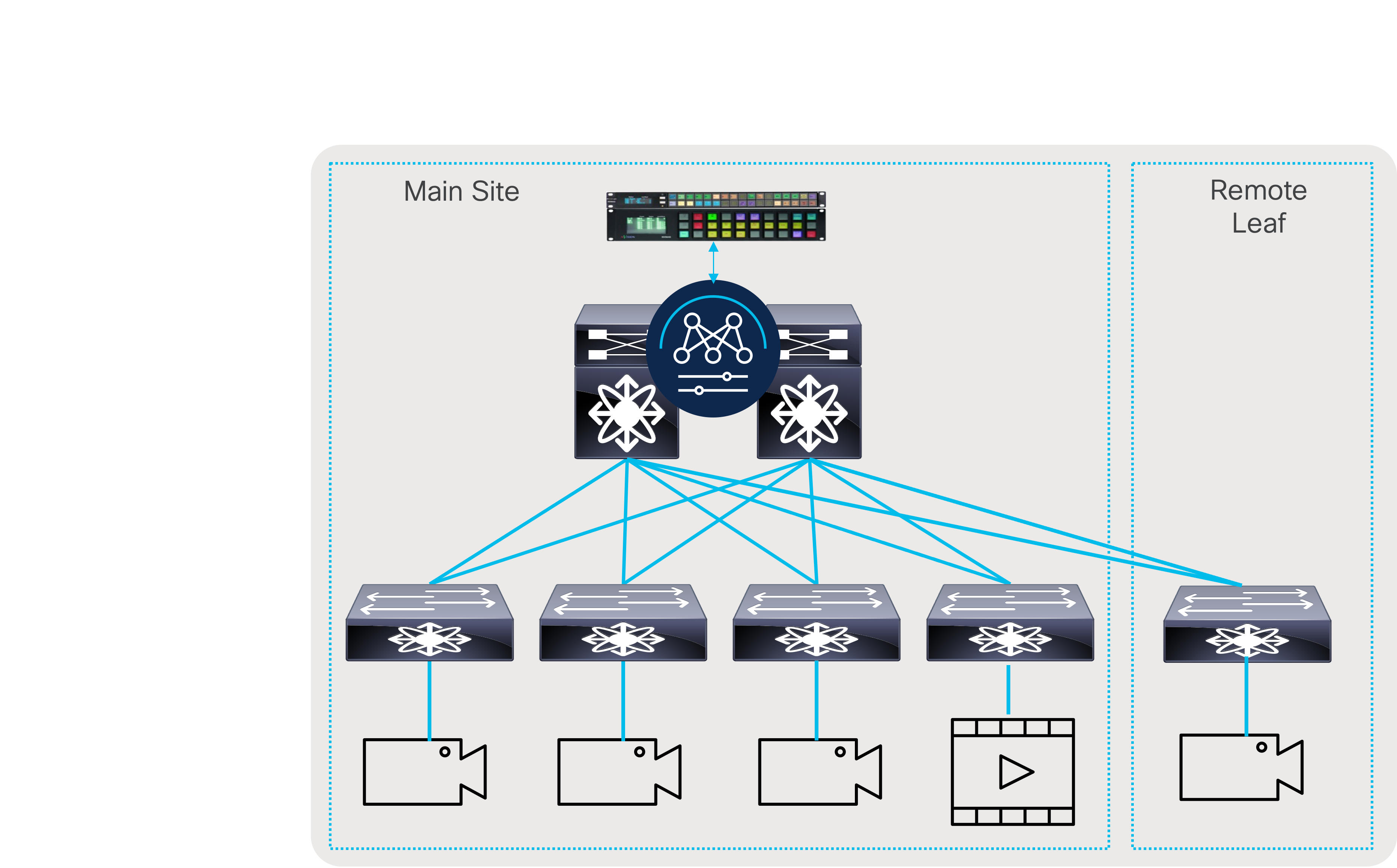
Remote leaf
In large broadcast facilities that have affiliates across the country, the fabrics can be interconnected, and flows can be transported across the facilities.
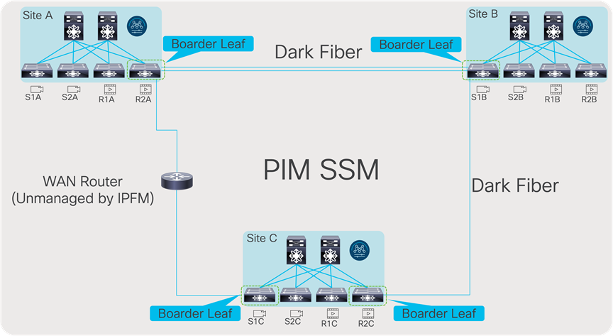
Multi-site deployment
Live Production and File Workflow on the same IP Fabric
The primary benefit of moving to IP is to enable production in higher definition. IP can also help consolidate different resources into a single IP infrastructure. In deployments today, encoders that convert uncompressed video to compressed format typically have an SDI interface connected to an SDI router from which they get compressed flows and an IP interface connected to an IP fabric for compressed workflows. With production now being done in IP, the same encoder can subscribe to an uncompressed 2110 stream, compress it, and transmit it back as a compressed stream on the same IP fabric. Other media assets that are virtualized and running on a server can simply be connected to the IP fabric. IP storage can also be plugged into the fabric. Using QoS, one can easily prioritize one type of traffic over the other (Figure 68).
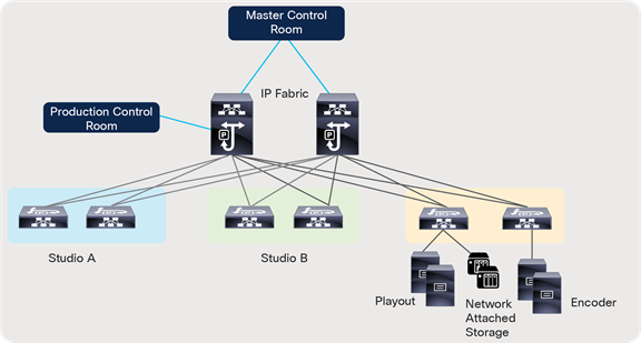
Converged fabric for media
The broadcast media and entertainment industry is going through a massive transformation with the move to IP. The move is happening now and happening quickly. The industry brings in unique challenges and requirements due to the workloads carried in the IP infrastructure. Along with multicast transport, the need to build a secure fabric with visibility to flows and fabric health is needed. Cisco’s IP Fabric for Media addresses all of these requirements by offering both a flexible and scalable spine and leaf fabric as well as a deployment with a single modular switch. The solution with the Cisco NBM feature offers reliable multicast transport as well as complete control on who is permitted to participate in the fabric. The solution offers remote production capability with the multi-site feature, which enables the ability to move any workload anywhere. With open APIs and the flexibility to integrate with NDFC or integrate directly on the switch, any third-party broadcast controller can interface with the network, abstracting any complexity, and provide the end operator an unchanged experience with IP.
● Cisco Nexus 9000 Series NX-OS IP Fabric for Media Solution Guide, Release 10.4.x
● Cisco NDFC-Fabric Controller Configuration Guide, Release 12.1.2e
● Cisco Nexus 9200 Platform Switches Data Sheet
● Cisco Nexus 9300-EX/FX/FX2/FX3/GX/GX2AB Platform Switches Data Sheet
https://www.cisco.com/c/en/us/products/switches/nexus-9000-series-switches/datasheet-listing.html
● Cisco Nexus 9500 R-Series Data Sheet
● Cisco Nexus 9800 Data Sheet
Legal Information
Cisco and the Cisco logo are trademarks or registered trademarks of Cisco and/or its affiliates in the U.S. and other countries. To view a list of Cisco trademarks, go to this URL: https://www.cisco.com/c/en/us/about/legal/trademarks.html. Third-party trademarks mentioned are the property of their respective owners. The use of the word partner does not imply a partnership relationship between Cisco and any other company. (1721R)
Any Internet Protocol (IP) addresses and phone numbers used in this document are not intended to be actual addresses and phone numbers. Any examples, command display output, network topology diagrams, and other figures in the document are shown for illustrative purposes only. Any use of actual IP addresses or phone numbers in illustrative content is unintentional and coincidental.
© 2023-2024 Cisco Systems, Inc. All rights reserved.