Cisco Nexus 9500 Cloud Scale Line Cards and Fabric Modules White Paper
Available Languages
Bias-Free Language
The documentation set for this product strives to use bias-free language. For the purposes of this documentation set, bias-free is defined as language that does not imply discrimination based on age, disability, gender, racial identity, ethnic identity, sexual orientation, socioeconomic status, and intersectionality. Exceptions may be present in the documentation due to language that is hardcoded in the user interfaces of the product software, language used based on RFP documentation, or language that is used by a referenced third-party product. Learn more about how Cisco is using Inclusive Language.
In 2016, Cisco first introduced products in the Cisco Nexus® 9000 Series Switch line based on Cisco® Cloud Scale intelligent Application-Specific Integrated Circuits (ASICs). The first Cloud Scale platforms enabled customers to build high-performance, cost-effective data center networks, supplementing or replacing 10G and 40G Ethernet with higher-capacity 25G and 100G connectivity options. Additional line card and fabric modules introduced over the subsequent years continued to expand and enhance the product family, offering numerous innovations to address the challenges of supporting Cloud Scale data centers, converged and hyperconverged infrastructure, and virtualized and containerized applications.
Most recently, the introduction of 400G Ethernet technology expands the Cloud Scale portfolio with platforms that provide high-density, high-performance top-of-rack aggregation, spine aggregation, and backbone connectivity options based on the GX Cloud Scale ASIC. With 400G options for modular systems, the GX line cards for the Nexus 9500 series chassis deliver several innovations in the industry, including 400G QSFP-DD (double density) transceivers that are fully backward-compatible with existing QSFP28 (100G) and QSFP+ (40G) transceivers, as well as wire-rate 256-bit AES MACSEC encryption capabilities for point-to-point connections.
Cisco Nexus 9500 modular switches equipped with Cloud Scale line cards and fabric modules can operate in both NX-OS mode, based on Cisco NX-OS Software, and ACI mode, based on Cisco Application Centric Infrastructure (Cisco ACI™). This flexibility enables customers to deploy Cisco Nexus 9500 platform switches in the mode that best fits their current operational model while keeping the option open to migrate to the other mode without the need for additional hardware investment or replacement.
This document discusses the hardware architecture of the Nexus 9500 Cloud Scale family of modular line cards and fabric modules, including forwarding capabilities, line card hardware architecture, and overall modular system architecture.
Overview: Cloud Scale Cisco Nexus 9500 Line Cards and Fabric Modules
The Cisco Nexus 9500 platform was originally launched in November 2013. It set new industry records at the time for 1, 10, and 40 Gigabit Ethernet port density, performance, power efficiency, and cost effectiveness. Today, the Cisco Nexus 9500 Cloud Scale line cards and fabric modules offer even more capacity and capability, with the addition of 25, 50, 100, and most recently, 400 Gigabit Ethernet speeds, increased forwarding scalability, and a set of network innovations that help organizations build Cloud Scale data center networks with outstanding visibility and security.
As of early-2021, the family of Cisco Nexus 9500 Cloud Scale line cards and fabric modules include the products listed in Table 1 (Cloud Scale line cards) and Table 2 (Cloud Scale fabric modules).
Table 1. Cisco Nexus 9500 Cloud Scale Line Cards
| Product |
Description |
| N9K-X9716D-GX |
16 x 400-Gbps ports, or up to 128 x 400-Gbps ports per switch, based on GX silicon |
| N9K-X9736C-FX |
36 x 100-Gbps ports, or up to 576 x 100-Gbps ports per switch, based on FX silicon |
| N9K-X9732C-FX |
32 x 100-Gbps ports, or up to 512 x 100-Gbps ports per switch, based on FX silicon |
| N9K-X9788TC-FX |
48 x 10-Gbps ports + 4 x 100-Gbps ports, for up to 768 x 10-Gbps ports + 64 x 100-Gbps ports per switch, based on FX silicon |
| N9K-X9736C-EX |
36 x 100-Gbps ports, for up to 576 x 100-Gbps ports per switch, based on EX silicon |
| N9K-X9732C-EX |
32 x 100-Gbps ports, for up to 512 x 100-Gbps ports per switch, based on EX silicon |
| N9K-X97160YC-EX |
48 x 25-Gbps ports + 4 x 100-Gbps ports, for up to 768 x 25-Gbps ports + 64 x 100-Gbps ports per switch, based on EX silicon |
Table 2. Cisco Nexus 9500 Cloud Scale Fabric Modules
| Product |
Description |
| N9K-C9508-FM-G |
1.6-Tbps Cloud Scale fabric module for the Cisco Nexus 9508 Switch chassis, providing up to 6.4-Tbps per slot and 51.2-Tbps per switch |
| N9K-C9504-FM-G |
1.6-Tbps Cloud Scale fabric module for the Cisco Nexus 9504 Switch chassis, providing up to 6.4-Tbps per slot and 25.6-Tbps per switch |
| N9K-C9516-FM-E2 |
800-Gbps Cloud Scale fabric module for the Cisco Nexus 9516 Switch chassis, providing up to 3.6-Tbps per slot and 57.6-Tbps per switch |
| N9K-C9508-FM-E2 |
800-Gbps Cloud Scale fabric module for the Cisco Nexus 9508 Switch chassis, providing up to 3.6-Tbps per slot and 28.8-Tbps per switch |
| N9K-C9516-FM-E |
800-Gbps Cloud Scale fabric module for the Cisco Nexus 9516 Switch chassis, providing up to 3.6-Tbps per slot and 57.6-Tbps per switch |
| N9K-C9508-FM-E |
800-Gbps Cloud Scale fabric module for the Cisco Nexus 9508 Switch chassis, providing up to 3.6-Tbps per slot and 28.8-Tbps per switch |
| N9K-C9504-FM-E |
800-Gbps Cloud Scale fabric module for the Cisco Nexus 9504 Switch chassis, providing up to 3.6-Tbps per slot and 14.4-Tbps per switch |
All Cisco Nexus 9500 chassis types, including Cisco Nexus 9504, 9508, and 9516 chassis, can support any of the Cloud Scale line cards and fabric modules[1] . They do not require chassis replacement, and in most cases require no changes or upgrades on the chassis common components, including the supervisors, system controllers, chassis fan trays, or power supply modules.[2] This approach helps protect the investments of customers who want to maintain their current investment in the Cisco Nexus 9500 platform switches while adopting 25, 50, 100, and 400 Gigabit Ethernet technologies.
The Cisco Nexus 9500 platform uses a folded Clos topology (often referred to as a fat-tree topology) internally to connect the fabric modules and the line cards. As shown in Figure 1, the ASICs on the fabric modules form the spine layer, and the ASICs on the line cards form the leaf layer.
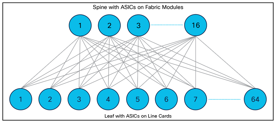
Internal Folded Clos Architecture of Cisco Nexus 9500 Platform Switches
The Clos topology keeps the switch internal architecture simple and consistent with the overall data center network architecture. It eliminates the need for a switching fabric between line cards. Unlike switching fabric architectures that require complex Virtual output Queue (VoQ) buffer management to avoid head-of-line blocking, the architecture for the Cisco Nexus 9500 platform is implemented with a simple and intelligent shared-memory egress buffered architecture.
The Cisco Nexus 9500 fabric modules and line cards are physically interconnected through direct attachment with connecting pins. Line cards are inserted horizontally, and fabric modules are inserted vertically, giving line cards and fabric modules orthogonal orientations in the chassis so that each fabric module is connected to all line cards, and all line cards are connected to all fabric modules. This direct attachment eliminates the need for a switch chassis midplane. Figure 2 depicts the orthogonal interconnection of line cards and fabric modules and the midplane-free chassis of a Cisco Nexus 9500 platform switch.
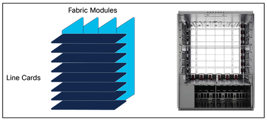
Cisco Nexus 9500 Line Cards and Fabric Modules Interconnection
The midplane-free chassis design offers several advantages:
● Allows the most direct and efficient airflow for cooling line cards and fabrics
● Increases chassis reliability by reducing the number of components in the system
● Makes upgrading to new-generation line cards and fabric modules easier, without the need to upgrade the chassis or midplane for higher interconnection speeds
This design enables the Cisco Nexus 9500 platform chassis to support multiple generations of line cards and fabric modules, providing a long lifespan for the system and excellent investment protection for the switch chassis and common components.
Cisco Cloud Scale Data Center Switching ASICs
The Cloud Scale ASICs used in the modular Nexus 9500 take advantage of cutting-edge semiconductor device fabrication techniques, using the 16nm FinFET Plus (16FF+) lithography process. Newer fabrication techniques enable higher transistor density and lower power consumption, features that are essential to build ASICs with more bandwidth, more ports, larger forwarding tables, larger buffers, and integration of new and more advanced capabilities.
The Cloud Scale ASICs provide speeds up to 400Gbps to data center networks at an optimal cost point and with increased performance. Table 3 and Table 4 show the port capacities of the different ASICs that are used to build the Cisco Nexus 9500 Cloud Scale line cards and fabric modules.
Table 3. Cisco Cloud Scale ASIC Port Capacity – Line Cards
| Role |
10 GE Ports |
25 GE Ports |
40 GE Ports |
100 GE Ports |
400 GE Ports |
|
| LS6400GX |
Line Card (GX) |
64 |
64 |
16 |
64 |
16 |
| LS1800FX |
Line Card (FX) |
80 |
72 |
20 |
18 |
N/A |
| LSE |
Line Card (EX) |
80 |
72 |
20 |
18 |
N/A |
Table 4. Cisco Cloud Scale ASIC Port Capacity – Fabric Modules
| ASIC |
Role |
100 GE Ports |
400 GE Ports |
| LS6400GX |
Fabric (FM-G) |
64 |
16 |
| S6400 |
Fabric (FM-E2) |
64 |
N/A |
| ASE2 |
Fabric (FM-E) |
36 |
N/A |
In addition to the need for cost-effective, high-speed Ethernet support, other key changes taking place in the data center need to be addressed. Virtual machines, which have become common elements in most data centers, are being joined and in many cases replaced by container-based workloads. The distributed storage functions built for big data are rapidly being used in other environments. Automation and dynamic resource allocation are resulting in a far more dynamic environment that complicates both security and day-two operations. These and other new requirements motivated Cisco to focus on delivering more capabilities and innovations in the next generation of switching.
The shifts in application development and the associated growth in the use of containers and micro-services are affecting many aspects of data center design, including the scaling requirements. As servers are disaggregated into their component services—for example, as each process or thread becomes an endpoint—the result is an increase in the number of addressable endpoints by an order of magnitude or more. When aggregated across even a small number of racks, the increase in network scaling requirements becomes substantially greater than the increase required by virtualization. The exponential increase in the number of endpoints per rack resulting from the use of containers and the overall increase in the total number of endpoints in the data center both contribute to the increased scaling requirements. Cisco is responding to these requirements by using some of the additional transistor capacity offered by next-generation switch ASICs for increased route and end-host scale.
Cisco’s Cloud Scale ASICs use a Flexible Forwarding Table (FFT) comprised of Flex Tiles, which allows forwarding table resources to be shared among different forwarding functions. The forwarding table can be carved for various forwarding lookup operations such as lookups for Layer 2 (MAC addresses), IPv4/IPv6 host entries, IPv4/IPv6 Longest-Prefix Match (LPM), next-hop adjacency information, Multiprotocol Label Switching (MPLS) labels, and multicast entries. The flexibility to program different resources as needed in the Flex Tiles empowers customers to deploy a common set of next-generation products for a wide range of data center applications. In addition to the Flex Tiles, additional Ternary Content-Addressable Memory (TCAM) is available to handle exception cases for Layer 2 and Layer 3 lookups.
Table 5 shows the raw Flex Tile sizes of the Cloud Scale line card ASICs. Software provides multiple scaling templates that resize the different forwarding tables in the Flex Tiles to accommodate different deployment scenarios. In addition to the default profile, templates for large-scale multicast deployments, Internet peering deployments, large-scale MPLS deployments, and large-scale ACI policy configurations address different key use cases.
Table 5. Cloud Scale ASIC Flex Tiles Sizes
| ASIC |
Flex Tiles |
| LS6400GX (GX line cards) |
34 tiles, 32K entries each, 104 bits per entry – 1088K total entries |
| LS1800FX (FX line cards) |
34 tiles, 32K entries each, 104 bits per entry – 1088K total entries |
| LSE (EX line cards) |
17 tiles, 32K entries each, 104 bits per entry – 544K total entries |
Although cost-effective bandwidth and port density will always be critical requirements in data center design, these are not the only requirements associated with the mixing of various traffic types such as distributed storage and distributed application inter-process communication. Algorithm improvements plus the availability of more transistors for buffers are allowing Cisco to deploy intelligent buffering that provides both larger buffers than many merchant silicon Switch-on-a-Chip (SOC) designs and multiple enhanced buffer and queuing management features, including:
● Dynamic buffer management – ensuring fair buffer access for congested queues in a shared-memory architecture
● Elephant Traps (ETRAP) – providing fine-grained flow identification and bandwidth characterization to identify high-bandwidth long-lived TCP flows
● Approximate Fair Drop (AFD) – maximizing the efficient use of available buffer while maintaining maximum throughput
● Dynamic Packet Prioritization (DPP) – facilitating initial flow setup and speeding flow completion time
● Explicit Congestion Notification (ECN) and Priority Flow Control (PFC) – optimizing RoCEv1/v2 traffic flows
The intelligent buffering functions, including AFD, ETRAP, and DPP, add flow awareness to the active queue management, allowing Cloud Scale switches to differentiate flows based on the data transfer sizes and treat them differently. Small flows can be prioritized over larger flows using an “express lane” on the egress port if they are more sensitive to packet drops or queue latency. Meanwhile, the AFD mechanism can be applied to sustained bandwidth flows, with discards applied to each flow proportional to the difference between the flow’s data-arrival rate and the computed fair rate. This approach achieves fairness among flows based on their data rate. The overall results of intelligent buffer management are higher application performance and better support for applications with microbursts/incast flows mixed with larger flows along the same network path.
Cloud Scale ASICs also support ECN, marking IP packets prior to buffers becoming exhausted and serving as a signal to applications to reduce their transmission rates to avoid congestion, as well as PFC, providing a per-class pause mechanism. ECN and PFC provide critical mechanisms for successful deployment of RDMA over Converged Ethernet (RoCE).
The shift to more efficient cloud-based provisioning requires new diagnostic and operational characteristics for the data center network. The operations team’s knowledge of where a server was and what it was doing started to alter with early virtualization technologies and will change entirely as the use of Linux containers continues to expand. The need to understand far more about the state of the infrastructure and the state of the applications running on the infrastructure requires more telemetry information than has traditionally been available.
Cisco Cloud Scale ASICs support several hardware-based sources of analytic information, including
● Hardware Flow Table with direct hardware export capability for tracking data-plane packet flows
● Flow Table Event capability to capture flow data based on specific events or criteria, including forwarding and buffer drops
● Flexible counters providing statistics for a wide variety of data-plane functions
● Fully hardware-based Switched Port Analyzer (SPAN) with dedicated per-egress port SPAN queue
● Encapsulated Remote SPAN (ERSPAN) sessions with Type 3 support (nanosecond timestamps)
● SPAN filtering via ACL and support for arbitrary User-Defined Fields (UDFs) providing visibility beyond Layer 4 headers
● Fine-grained, configurable per-queue microburst detection mechanism
● Embedded logic analyzers for quickly isolating forwarding issues
● TTAG support for in-band packet timestamping
● IEEE 1588 latency measurements
High-performance VXLAN routing
Virtual Extensible LAN (VXLAN) has rapidly become the industry-standard overlay technology for building more scalable and reliable data center fabrics that support application workload mobility and provide network agility that matches the needs of applications. To move business-critical applications onto the VXLAN overlay fabric, high performance for both Layer 2 bridging and Layer 3 routing in the VXLAN overlay network is essential.
Many merchant-silicon ASICs are not built to support VXLAN routing natively – they sacrifice forwarding performance to provide VXLAN functions. Cisco Cloud Scale ASICs perform single-pass VXLAN routing for both Layer 2 and Layer 3 VXLAN, providing uncompromised forwarding bandwidth and latency performance regardless of whether performing native IP routing or performing VXLAN encapsulation for an overlay network.
Changing requirements for the network include more than increased capacity and better operational characteristics. Virtualization, containers, storage, and multitenancy also require basic improvements in the forwarding and security functions. More sophisticated tunneling and forwarding capabilities, which used to be limited to expensive backbone routers, have been made possible in high-speed data center networks through continued ASIC innovation. With the Cisco Cloud Scale ASICs, features such as segment routing, Group-Based Policy (GBP) for security, Network Service Header (NSH), and full-featured VXLAN overlays are available, at greater scale and in more efficient devices:
● Single-pass VXLAN tunnel gateway
● GBP VXLAN
● VXLAN routing
● Bidirectional (Bidir) Protocol-Independent Multicast (PIM)
● NSH
● Push 5+2 (Fast Reroute [FRR]) MPLS labels
● Security Group Tag (SGT) and Endpoint Group (EPG) mapping
● Unified ports
Although many of these features are available at lower scale in merchant-silicon switches, Cisco takes advantage of the feature scale supported by the new ASIC designs to offer an additional set of features that can benefit more traditional data center customers, including Fibre Channel and unified ports, and interoperation with Cisco TrustSec® SGTs.
Note: While Cisco’s Cloud Scale ASICs are designed and built with the features described here, software support for some of features may not yet be available. To verify the supported features in a given software release, refer to the corresponding software release notes.
Cisco Nexus 9500 Cloud Scale Fabric Modules
The Cisco Nexus 9500 platform switches use the Cloud Scale fabric modules to provide high-bandwidth interconnections between line-card slots. The Cloud Scale fabric modules are built with one of three different high-density ASICs, depending on the model. The number of line card slots in the Cisco Nexus 9500 chassis determines the number of ASICs used to build the fabric module. Table 6 summarizes the number of ASICs and the number of Ethernet ports provided by each of the fabric modules for the different chassis types.
Table 6. Cisco Nexus 9500 Platform Switches Internal Port Capacity in Cloud Scale Fabric Modules
| Chassis and Fabric Module |
ASIC |
Number of ASICs per FM |
Number of 100-Gbps Ports per FM |
Number of 400-Gbps Ports per FM |
| Cisco Nexus 9508 with FM-G |
LS6400GX |
1 |
64 |
16 |
| Cisco Nexus 9504 with FM-G |
LS6400GX |
1 |
64 |
16 |
| Cisco Nexus 9516 with FM-E2 |
S6400 |
2 |
128 |
N/A |
| Cisco Nexus 9508 with FM-E2 |
S6400 |
1 |
64 |
N/A |
| Cisco Nexus 9516 with FM-E |
ASE2 |
4 |
128 (treated as 256 x 50-Gbps)1 |
N/A |
| Cisco Nexus 9508 with FM-E |
ASE2 |
2 |
64 |
N/A |
| Cisco Nexus 9504 with FM-E |
ASE2 |
1 |
32 |
N/A |
The Cloud Scale fabric modules in the Cisco Nexus 9500 platform switches provide high-speed data-forwarding connectivity between the line cards. In some cases, the fabric modules also perform unicast or multicast lookups, and provide a distributed packet replication function to send copies of multicast packets to egress ASICs on the line cards. With FM-E or FM-E2, the fabric modules installed in slots 2, 4, and 6 also provide the power connection to the chassis fan trays – therefore a minimum of three fabric modules is required for normal chassis operation. With FM-G, all fabric module slots must be populated to provide power to the fan trays – either FM-G modules (up to 5) or FM-PWR filler cards can be used.
For most Cloud Scale modular deployments, we recommend four fabric modules to provide maximum bandwidth and redundancy for the line cards. With each fabric module providing either 1.6-Tbps (FM-G) or 800-Gbps (FM-E/FM-E2) of bandwidth to each line card slot, with four fabric modules installed each line card has access to either 6.4-Tbps (12.8-Tbps bidirectional) or 3.2-Tbps (6.4-Tbps bidirectional) total bandwidth toward other modules in the chassis. With four fabric modules, install the modules in fabric slots 2, 3, 4, and 6.
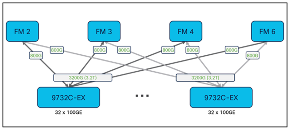
Figure 3 shows the internal connectivity of a Cisco Nexus 9508 Cloud Scale switch, using FM-E and 9732C-EX modules as an example of the internal architecture. In this case, each fabric module consists of two ASE2 ASICs and provides 800-Gbps to each of the line cards, for a total of 3.2-Tbps per line card slot.
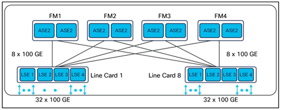
Cisco Nexus 9508 Cloud Scale Switch Internal Connectivity – FM-E and 9732C-EX
Note that certain Cloud Scale modules such as the 9736C-EX and 9736C-FX provide additional front-panel ports to maximize density – with four fabric modules these line cards are oversubscribed 1:1.125 into the fabric. However, the 9736C-FX adds a fifth fabric connector and supports full 3.6-Tbps bandwidth with five fabric modules installed, provided only 9736C-FX modules are present in the system. When using a fifth fabric module, install the module in fabric slot 5.
Fabric redundancy in Nexus 9500 Cloud Scale systems generally follows a graceful bandwidth de-rating model. If a fabric module fails, all line card ports continue to function but the available per-slot bandwidth available to the line cards toward the fabrics is reduced by either 1.6-Tbps or 800-Gbps, depending on the fabric module and line card type. Note that the 9732C-FX module adds a fifth fabric connector and supports N+1 fabric module redundancy with five fabric modules installed, provided only 9732C-FX modules are present in the system. When using a fifth fabric module, install the module in fabric slot 5.
Cisco Nexus 9500 Cloud Scale Line Cards
The Cisco Nexus 9500 Cloud Scale line cards provide the front-panel interface connections for the network and connect to the other line cards in the system through the Cloud Scale fabric modules. Cloud Scale line cards consist of multiple ASICs, depending on the required port types and density – for example, 10/25-Gbps line cards use two ASICs, while 100-Gbps line cards use four. The line card ASICs perform the majority of forwarding lookups and other operations for packets ingressing or egressing the system, but the fabric modules may perform certain functions as well in a distributed and scalable fashion.
In addition to the ASIC resources used for high-performance data-plane packet forwarding, Cisco Nexus 9500 Cloud Scale line cards have an on-board dual-core x86 CPU as well. This CPU is used to offload or speed up some control-plane tasks, such as programming the hardware tables, collecting line-card counters and statistics, and offloading Bidirectional Forwarding Detection (BFD) protocol handling from the supervisor. These capabilities significantly improve system control-plane performance.
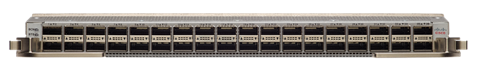
The Cisco Nexus N9K-X9732C-EX line card provides 32 x 100 Gigabit Ethernet Quad Small Form-Factor Pluggable 28 (QSFP28) ports. Figure 4 shows the front of the line card.
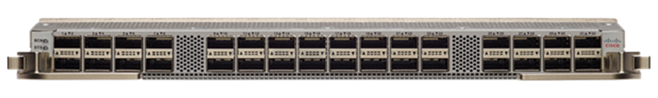
Front of N9K-X9732C-EX Line Card
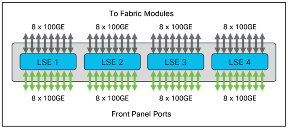
The 9732C-EX line card uses four instances of the Cisco LSE ASIC to provide forwarding functions. While each LSE ASIC has 18 x 100 Gigabit Ethernet ports, only 16 ports are used on the 9732C-EX line card to help guarantee full line-rate performance for all packet sizes with the folded Clos architecture of four fabric modules. Among the 16 active ports on each LSE, 8 ports are used as front-panel ports, and the other 8 ports are used internally to connect to the fabric modules. Figure 5 illustrates the internal architecture of the 9732C-EX line card.
N9K-X9732C-EX Line-Card Architecture
With four Cloud Scale fabric modules, the chassis provides each 9732C-EX line card with 3.2-Tbps bandwidth, as shown in Figure 6.
N9K-X9732C-EX Fabric Connectivity
In addition to 100 Gigabit Ethernet, each front-panel port also supports 2 x 50, 1 x 40, 4 x 25, 4 x 10, and 1 x 1/10 Gigabit Ethernet speeds. When a port is populated with a QSFP28 transceiver, it can operate as a single 100 Gigabit Ethernet port, or it can break out to two 50 Gigabit Ethernet ports or four 25 Gigabit Ethernet ports. When a port has a QSFP+ transceiver plugged in, it can run as a single 40 Gigabit Ethernet port, or it can break out to four 10 Gigabit Ethernet ports. With an appropriate QSFP-to-SFP adaptor (QSA), a single port can also operate at 10 and 1 Gigabit Ethernet speeds.
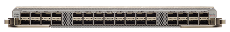
The Cisco Nexus N9K-X9736C-EX line card provides 36 x 100 Gigabit Ethernet QSFP28 ports. Figure 7 shows the front of the line card.
Front of N9K-X9736C-EX Line Card
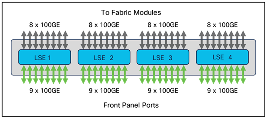
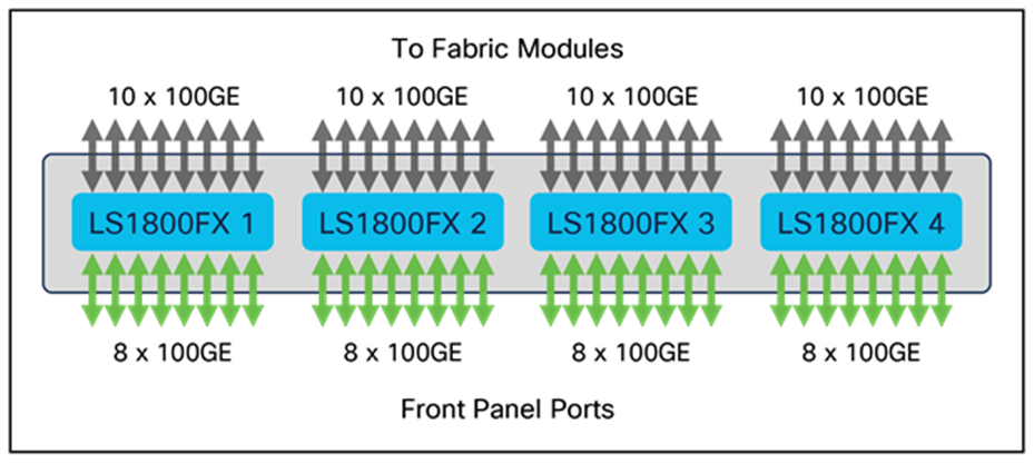
Like the 9732C-EX line card, the 9736C-EX line card uses four instances of the Cisco LSE ASIC to provide forwarding functions. However, the 9736C-EX line card uses one additional port on each LSE to maximize the front-panel port density – 9 ports are used as front-panel ports, and 8 ports are used internally to connect to the fabric modules, resulting in a 1:1.125 oversubscription ratio. Figure 8 illustrates the internal architecture of the 9736C-EX line card.
N9K-X9736C-EX Line-Card Architecture
With four Cloud Scale fabric modules, the chassis provides each 9736C-EX line card with 3.2-Tbps bandwidth, as shown in Figure 9.
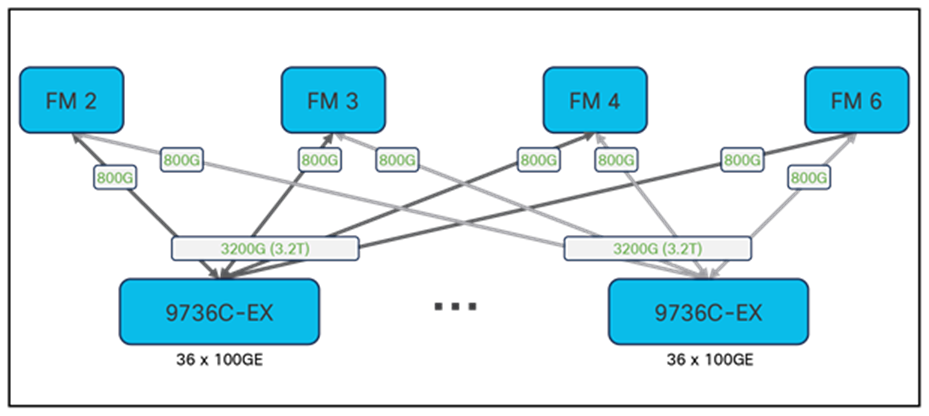
N9K-X9736C-EX Fabric Connectivity
In addition to 100 Gigabit Ethernet, each front-panel port also supports 2 x 50, 1 x 40, 4 x 25, 4 x 10, and 1 x 1/10 Gigabit Ethernet speeds.
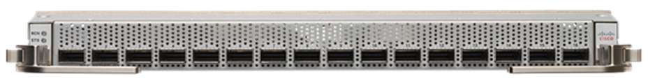
The Cisco Nexus N9K-X9732C-FX line card provides 32 x 100 Gigabit Ethernet QSFP28 ports. Figure 10 shows the front of the line card.
Front of N9K-X9732C-FX Line Card
The 9732C-FX line card uses four instances of the Cisco LS1800FX ASIC to provide forwarding functions. This line card adds a fifth fabric module connector, providing N+1 fabric module redundancy with five fabrics, when all the line cards in the chassis are 9732C-FX. Up to 10 x 100G links from each LS1800FX ASIC connect to the fabric modules, while 8 x 100G links from each ASIC support the front-panel interfaces. Figure 11 illustrates the internal architecture of the 9732C-FX line card.
N9K-X9732C-FX Line-Card Architecture
With four Cloud Scale fabric modules, the chassis provides each 9732C-FX line card with 3.2-Tbps bandwidth. When you add a fifth fabric module, the chassis provides 4-Tbps per slot as shown in Figure 12, ensuring that even when a fabric module fails, the full 3.2-Tbps bandwidth needed for the front-panel ports remains available.
N9K-X9732C-FX Fabric Connectivity
In addition to 100 Gigabit Ethernet, each front-panel port also supports 2 x 50, 1 x 40, 4 x 25, 4 x 10, and 1 x 1/10 Gigabit Ethernet speeds. All ports on the 9732C-FX module also have MACSEC capability, providing line-rate, hardware-based 256-bit AES hop-by-hop encryption.
The Cisco Nexus N9K-X9736C-FX line card provides 36 x 100 Gigabit Ethernet QSFP28 ports. Figure 13 shows the front of the line card.
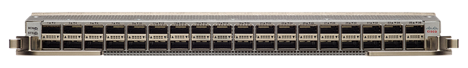
Front of N9K-X9736C-FX Line Card
The 9736C-FX line card uses four instances of the Cisco LS1800FX ASIC to provide forwarding functions, along with four instances of an ASIC providing advanced encryption capabilities for a subset of the front-panel ports. This line card also adds a fifth fabric module connector, providing full bandwidth for all 36 ports with five fabrics installed, when all of the line cards in the chassis are 9736C-FX. 9 x 100G links from each LS1800FX ASIC connect to the fabric modules, while 9 x 100G links from each ASIC support the front-panel interfaces. Figure 14 illustrates the internal architecture of the 9736C-FX line card.
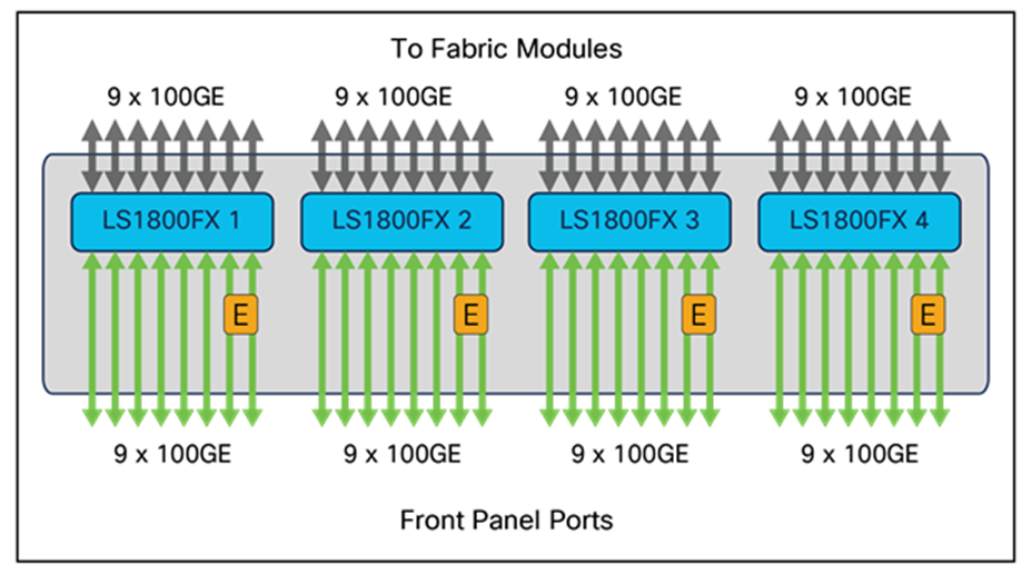
N9K-X9736C-FX Line-Card Architecture
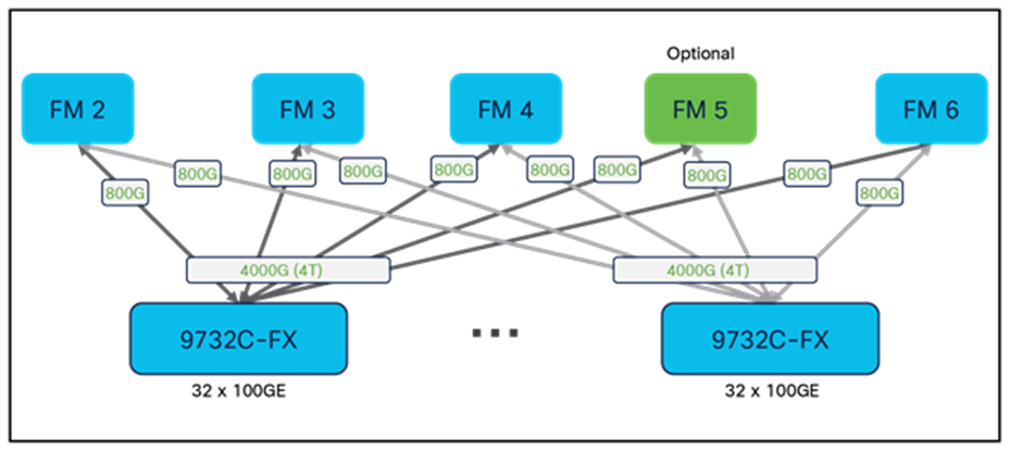
With four Cloud Scale fabric modules, the chassis provides each 9736C-FX line card with 3.2-Tbps bandwidth. When you add a fifth fabric module, the chassis provides 3.6-Tbps per slot as shown in Figure 15, ensuring full bandwidth for all front-panel ports.
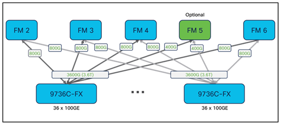
N9K-X9736C-FX Fabric Connectivity
In addition to 100 Gigabit Ethernet, each front-panel port also supports 2 x 50, 1 x 40, 4 x 25, 4 x 10, and 1 x 1/10 Gigabit Ethernet speeds. All ports on the 9736C-FX module also have MACSEC capability, providing line-rate, hardware-based 256-bit AES hop-by-hop encryption.
The Cisco Nexus N9K-X9716D-GX line card provides 16 x 400 Gigabit Ethernet Quad Small Form-Factor Pluggable Double-Density (QSFP-DD) ports. Figure 4 shows the front of the line card.
Front of N9K-X9716D-GX Line Card
The 9716D-GX line card uses two instances of the Cisco LS6400GX ASIC to provide forwarding functions, along with eight instances of an ASIC providing MACSEC encryption capability on all front panel ports.
Among the 16 400G ports on each LS6400GX ASIC, 8 ports are used as front-panel ports, and the other 8 ports are used internally to connect to the fabric modules. Figure 17 illustrates the internal architecture of the 9716D-GX line card.
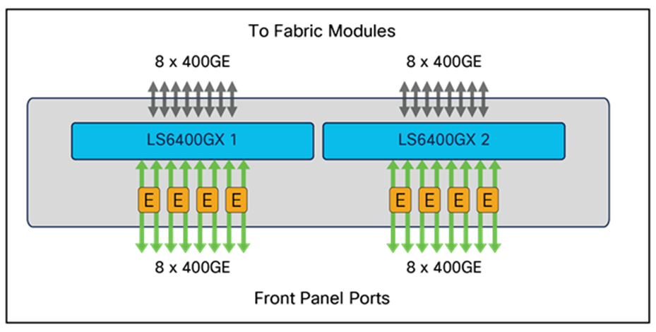
N9K-X9716D-GX Line-Card Architecture
With four Cloud Scale FM-G fabric modules, the chassis provides each 9716D-GX line card with 6.4-Tbps bandwidth, as shown in Figure 18. Note that the FM-G fabric modules require a corresponding fan tray upgrade in order to provide sufficient cooling for the system.
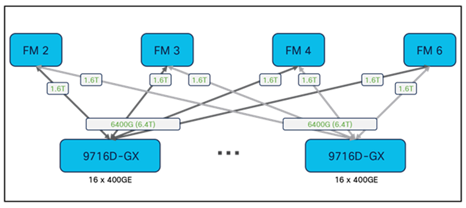
N9K-X9716D-GX Fabric Connectivity
In addition to 400 Gigabit Ethernet, each front-panel port also supports 10, 25, 40, 50, 100, and 200 Gigabit Ethernet speeds (subject to software support). When a port is populated with a QSFP-DD transceiver, it can operate as a single 400 Gigabit Ethernet port, or it can break out to four 100 Gigabit Ethernet ports. When a port has a QSFP28 transceiver plugged in, it can operate as a single 100 Gigabit Ethernet port, or it can break out to four 25G ports. When a port has a QSFP+ transceiver plugged in, it can run as a single 40 Gigabit Ethernet port, or it can break out to four 10 Gigabit Ethernet ports. With an appropriate QSFP-to-SFP adaptor (QSA), a port can also operate at 10 Gigabit Ethernet speeds.
Forwarding flexibility and scalability with Cloud Scale Line Cards and Fabric Modules
The forwarding lookups on the Cisco Cloud Scale ASICs use a shared pool of resources known as the flexible forwarding table, or FFT, to store Layer 2, Layer 3, and other forwarding information.
Because the line cards and fabric modules for the Cisco Nexus 9500 platform are both built with the Cloud Scale ASICs, they both have FFTs that can be used to program forwarding tables, allowing for hierarchical forwarding lookups that can increase the system-wide forwarding scalability. For example, the FFT on the line cards can be used to store the Layer 2 MAC address table and Layer 3 host table, and the FFT on the fabric modules can be used for Layer 3 LPM routes. Alternatively, the FFT on both line cards and the fabric modules can be used to program Layer 3 host routes and LPM routes, with IPv4 and IPv6 entries partitioned between them. Or, both line cards and fabric modules can have multicast tables and take part in distributed multicast lookups and packet replication.
The flexibility to partition entries between line cards and fabric modules allows the Cisco Nexus 9500 platform switches to optimize table resource utilization on the line cards and fabric modules and to increase the Layer 2 and Layer 3 forwarding scalability of the system. It also enables Cisco Nexus 9500 platform switches to be deployed in data centers at a broad range of scales with a variety of application types.
Table 7 shows one example of FFT partitioning between line cards and fabric modules: using fabric modules for IPv6 entries and using line cards for IPv4 and MAC address entries. This is only one example of how the FFT can be partitioned. Other approaches are possible: for instance, the number of IP host routes or LPM routes can be increased by fully using the table resources on both the line cards and fabric modules for the selected forwarding route types.
Table 7. FFT Partition Example
| Entry type |
FM-E fabric module (ASE2) |
9700-EX line card (LSE) |
Cisco Nexus 9500 platform |
| Layer 2 MAC addresses |
Not used |
16,000 |
16,000 |
| IPv4 host routes |
Not used |
1 million* |
1 million* |
| IPv4 LPM |
Not used |
1 million* |
1 million* |
| IPv6 LPM/64 |
320,000 |
Not used |
320,000 |
| IPv6 host routes |
4000 |
Not used |
4000 |
Packet forwarding with Cloud Scale Line Cards and Fabric Modules
This section describes the packet-forwarding process with the Cloud Scale line cards and fabric modules.
The data-plane forwarding architecture of the Cisco Nexus 9500 platform switches includes the ingress pipeline on the ingress line card, fabric module forwarding, and the egress pipeline on the egress line card. The ingress and egress pipelines can be run on different line cards, the same line card, or even within the a single ASIC on the line card if the ingress and egress ports are both on the same ASIC.
As shown in Figure 19, the forwarding pipeline for the Cloud Scale ASICs consists of the input forwarding controller, input data-path controller, egress data-path controller, and egress forwarding controller.
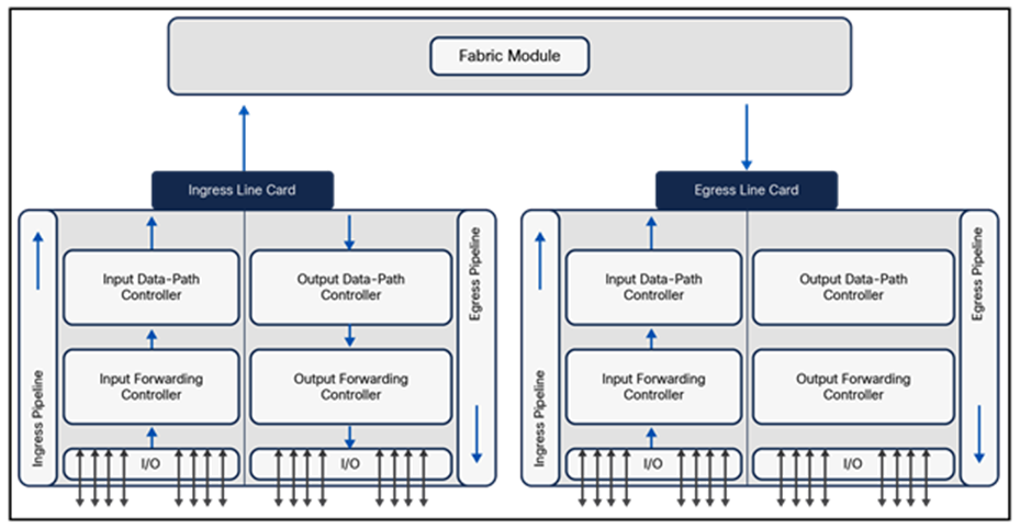
Forwarding Pipeline with New-Generation Line Cards and Fabric Modules
Each of the pipeline elements shown in Figure 16 can consist of multiple forwarding processing steps. Figure 20 illustrates the detailed steps in the Cloud Scale ASIC pipelines.
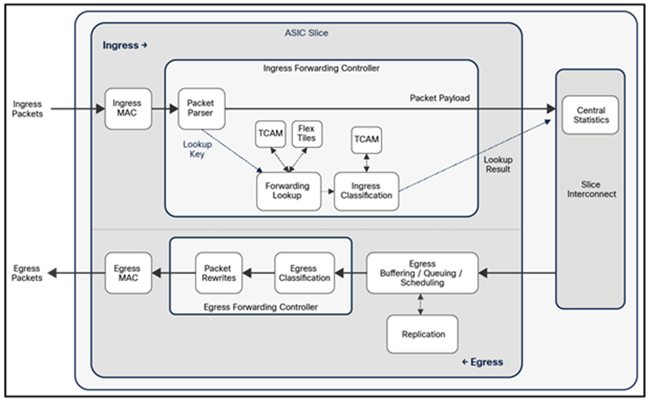
Detailed Forwarding Steps in the ASIC Pipeline
The ingress forwarding controller receives the packet from the MAC layer, parses the packet headers, and performs a series of lookups to decide whether to accept the packet and how to forward it to its intended destination. It also generates instructions to the data path for the storage and queuing of the packet.
When a packet arrives through a front-panel port, it goes through the ingress pipeline, and the first step is packet-header parsing. The flexible packet parser parses the first 128 bytes of the packet to extract and save information such as the Layer 2 header, EtherType, Layer 3 header, and TCP/UDP headers.
These parsed fields are used in a series of forwarding table and Access Control List (ACL) lookups to determine:
● Destination output interfaces (based on Ethernet learning, IP host route entries, LPM, etc.)
● Compliance of switching and routing protocols (spanning tree, VXLAN, Open Shortest Path First [OSPF], Fabric Shortest Path First [FSPF], Intermediate System–to–Intermediate System [IS-IS], redirects, IP packet checks, etc.)
● Policies (network access rights, storage zoning, permit or deny, security, etc.)
● Control-plane redirection and copying (Bridge Protocol Data Unit [BPDU], Address Resolution Protocol [ARP], Internet Group Management Protocol [IGMP], gleaning, etc.)
● System Class-of-Service (CoS) classification (input queue, output queue, IEEE 802.1p tagging, etc.)
● Service rates and policers
● SPAN (ingress, egress, drop, etc.)
● Statistics (flow and interface packets, byte counters, etc.)
● Network flow-based load balancing (multipathing, EtherChannels, etc.)
● Flow samplers (M of N bytes, M of N packets, etc.)
● Packet-header rewrites (next-hop addresses, overlay encapsulation, Time To Live [TTL], etc.)
● Flow table (to collect NetFlow and analytics information)
As a packet goes through the ingress pipeline, it is subject to multiple lookups, including Layer 2 switching and Layer 3 routing. First, the forwarding examines the destination MAC (DMAC) address of the packet to determine if the packet needs to be Layer 2 switched or Layer 3 routed. If the DMAC address matches the switch’s own router MAC address, the packet is passed to the Layer 3 routing lookup logic. If the DMAC address doesn’t belong to the switch, a Layer 2 switching lookup based on the DMAC address and VLAN ID is performed. If a match is found in the MAC address table, the packet is sent to the egress port. If no match is found for the DMAC address and VLAN combination, the packet is forwarded to all ports in the same VLAN.
In the Layer 3 lookup logic on the line card, the Destination IP (DIP) address is used for searches in the Layer 3 host table. This table stores forwarding entries for directly attached hosts or learned /32 host routes. If the DIP address matches an entry in the host table, the entry indicates the destination port, next-hop MAC address, and egress VLAN. If no match to the DIP address is found in the host table, an LPM lookup is performed in the LPM routing table.
When Layer 2 switching and Layer 3 routing is performed, if the egress port is local to the ASIC, packets will be forwarded locally without going to fabric modules. Otherwise, the packet is sent to one of the fabric modules for forwarding to the egress line-card ASIC.
In addition to forwarding lookups, the packet undergoes ingress classification processing. The classification TCAM is checked for ingress matches. As shown in Figure 21, each ASIC has TCAM to support system internal ACLs and user-defined ingress ACLs. These ACLs include Routed ACLs (RACLs), VLAN ACLs (VACLs), Port ACLs (PACLs), Network Address Translation (NAT) ACLs, and others. Classification entries are localized to each ASIC slice and programmed only where needed. This approach allows optimal use of the classification TCAM in a Cisco Nexus 9500 platform switch.
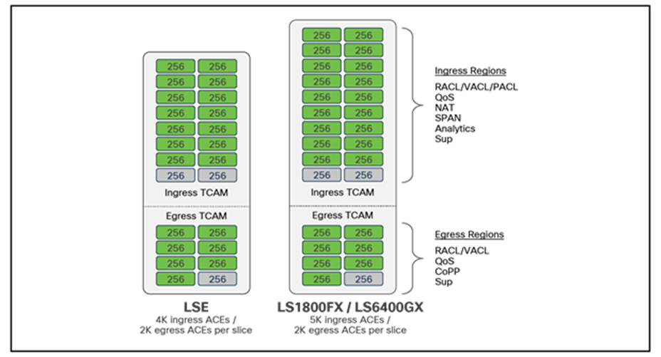
Classification TCAM on Cloud Scale ASICs
Cisco Nexus 9500 platform switches also support Quality of Service (QoS) ACLs, allowing traffic to be classified based on the address fields, IEEE 802.1q CoS, and IP precedence or Differentiated Services Code Point (DSCP) in the packet header. The classified traffic can be assigned to one of the eight internal QoS groups, which identify the traffic classes used for subsequent QoS processes as packets go through the system – for instance, in egress queueing.
Input Forwarding Result Generation
The final step in the ingress forwarding pipeline is to collect all the forwarding metadata generated earlier in the pipeline and pass it to the downstream blocks through the data path. A 64-byte internal header is stored along with the incoming packet in the packet buffer. This internal header includes 16 bytes of iETH (Insieme Ethernet) header information, which is added on the top of the packet when the packet is transferred to another chip in the modular chassis. This 16-byte iETH header is stripped off when the packet finally is sent out the front-panel port. The other 48 bytes of the internal header are used only to pass metadata from input forwarding to output forwarding and are consumed by the output forwarding controller.
The central statistics module provides per-packet internal ASIC statistics. Cloud Scale ASICs provide multiple counters per packet. The sources of the packet increments are:
● Input and output forwarding controllers: These controllers can flexibly count different types of forwarding events by passing up to eight indexes.
● Output data path controller. This controller uses the Central Statistics module to count input and drop statistics on a per-port per-class per-drop per-unicast/multicast/flood per-good/drop basis.
Egress buffering/queuing/scheduling and replication
Buffering, queuing, scheduling, and packet replication occur in the egress slice of the ASIC. All ports on a slice dynamically share the egress buffer and replication resources. The Cisco Nexus 9500 platform uses a shared-memory egress queuing architecture. In the event of egress port congestion, packets are directly queued in the buffer of the egress line card. There are no Virtual output Queues (VoQ) on the ingress line cards. This design greatly simplifies the system buffer management and queuing implementation. A Cisco Nexus 9500 platform switch can support up to 10 traffic classes on egress, including 8 user-defined classes identified by QoS group IDs, a strict-priority CPU control traffic class, and a best-effort SPAN traffic class. Each user-defined class handles both unicast and multicast traffic per egress port.
The output forwarding controller receives packets for transmission and any associated metadata from the buffer manager and is responsible for egress classification and all packet rewrites. It extracts the internal header and various packet header fields from the packet, performs a series of lookups, and generates the rewrite instructions.
When a packet is forwarded to a fabric module, the fabric module takes different actions depending on the lookup results on the ingress line card and the forwarding lookup functions programmed in the flex tiles on the fabric module. In the example shown in Table 7 in an earlier section, the fabric module has both the IPv6 host route and the IPv6 LPM route table while the ingress line card has the IPv4 host and LPM route tables as well as the Layer 2 MAC tables. If the packet is a Layer 2 switched or IPv4 routed packet, the ingress line card resolves the egress port, the next-hop MAC address, and the egress VLAN information. The fabric module simply forwards the packet to the correct egress line card. However, if the packet needs an IPv6 routing lookup, the line card forwards the packet to a fabric module which performs an IPv6 host route lookup and an IPv6 LPM lookup and uses the best match for the destination IPv6 address to forward the packet to the appropriate egress line card.
For multicast packets, the system needs to determine whether packets must undergo Layer 2 multicast forwarding, Layer 3 multicast forwarding, or both. A packet will go through Layer 3 multicast forwarding if it meets the following criteria:
● It is an IP packet with a multicast address.
● It is not a link-local packet.
● Multicast routing is enabled on the bridge domain.
For Layer 2 IP multicast packets, the forwarding lookup can be performed using either the Ethernet or IP header. By default, a Cisco Nexus 9500 platform switch uses the IP address for Layer 2 multicast forwarding lookups within a bridge domain.
For broadcast packets, the ASIC floods the packet in the bridge domain. The ASIC maintains separate per-bridge domain fanout lists for broadcast traffic and for unknown unicast traffic.
IP multicast forwarding in Cloud Scale ASICs relies on the Forwarding Information Base (FIB) table. For both Layer 2 and Layer 3 IP multicast, the switch looks up the IP address in the FIB table. The source address is used for the RPF check, and the destination address is used to determine the outgoing interface list. If the FIB destination address search doesn’t result in a match, the packet is classified as unknown multicast. If IGMP and Multicast Listener Discovery (MLD) snooping are enabled, the packet is forwarded to all router ports on which the incoming bridge domain is present. If snooping is disabled, the packet is flooded in the bridge domain.
Multicast packets go through the same ingress and egress processing pipelines as unicast packets. However, one difference in the packet lookup and forwarding process is that the Cisco Nexus 9500 platform switches perform three-stage distributed multicast lookup and replication. The multicast routing table is stored on all line cards and fabric modules. The ingress ASIC on the line card performs the first lookup to resolve local receivers. If any local receivers are present, a copy is sent to the local ports. The ingress ASIC then sends a copy of the incoming packet to one of the fabric modules based on flow hash. The receiving fabric module performs the second lookup to find the egress line cards. The fabric module replicates the packet to each egress line card on which there are receivers. The egress line card performs the third lookup to resolve its local receivers and replicates the packet on those ports. This multiple-stage multicast lookup and replication is the most efficient way of replicating and forwarding multicast traffic.
The Cloud Scale line cards and fabric modules for the Cisco Nexus 9500 platform switches are built with the latest technology to lead the ongoing data center switching transition to 100 Gigabit Ethernet and beyond. Cisco Nexus 9500 platform switches deliver high-density 25, 100, and 400 Gigabit Ethernet ports at a competitive cost point, while introducing advanced capabilities to meet the requirements in the data center for increased forwarding capacity, high-performance overlay solutions, intelligent buffer management, network telemetry and visibility, and more. With the Cloud Scale line cards and fabric modules, the Cisco Nexus 9500 platform switches provide the leading modular switch platform for building data center networks and outstanding support for converged and hyper-converged infrastructure.
http://www.cisco.com/c/en/us/products/switches/nexus-9000-series-switches/white-paper-listing.html.