Cisco Catalyst 9000 Platform StackWise Virtual White Paper
Available Languages
Bias-Free Language
The documentation set for this product strives to use bias-free language. For the purposes of this documentation set, bias-free is defined as language that does not imply discrimination based on age, disability, gender, racial identity, ethnic identity, sexual orientation, socioeconomic status, and intersectionality. Exceptions may be present in the documentation due to language that is hardcoded in the user interfaces of the product software, language used based on RFP documentation, or language that is used by a referenced third-party product. Learn more about how Cisco is using Inclusive Language.
Cisco® Catalyst® 9000 platform StackWise® Virtual technology allows the clustering of two physical switches together into a single logical entity. The two switches operate as one; they share the same configuration and forwarding state. This technology allows for enhancements in all areas of network design, including high availability, scalability, management, and maintenance.
Figure 1 graphically represents the StackWise Virtual feature, which allows you to manage two Cisco Catalyst 9000 Switches as a single switch.
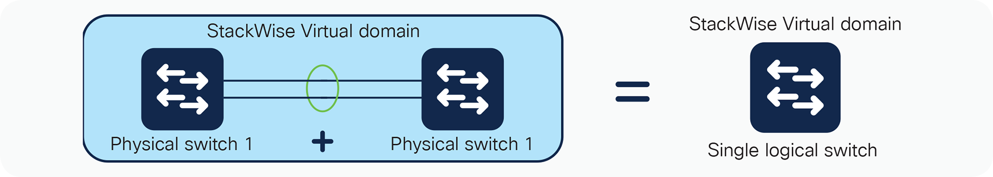
StackWise Virtual physical to logical representation
This paper explains the Cisco StackWise Virtual technology, including its benefits and requirements.
Cisco Catalyst 9000 platform StackWise Virtual: An overview
This virtualization of the two-physical switches into single logical switch fundamentally alters the design of campus topology. One of the most significant changes is that StackWise Virtual enables the creation of a loop-free topology because the two switches operate as one. Thus, the spanning-tree domain treats the StackWise Virtual pair as one bridge node instead of two. In addition, StackWise Virtual also incorporates many other Cisco innovations—such as Stateful Switch Over (SSO), Non-Stop Forwarding (NSF) and Multi-chassis EtherChannel (MEC)—that enable non-stop communication with increased bandwidth to substantially enhance application response time
Key business benefits of the SVL include the following:
● Reduced risk associated with a looped topology
● Non-stop business communication through the use of a redundant chassis with SSO-enabled supervisors
● Better return on existing investments via increased bandwidth from access layer
● Reduced configuration errors and elimination of First Hop Redundancy Protocols (FHRP), such as Hot Standby Routing Protocol (HSRP), GLBP and VRRP
● Simplified management of a single configuration and fewer operational failure points
Figure 2 graphically represents the benefits of transitioning from traditional architecture to StackWise Virtual Architecture.
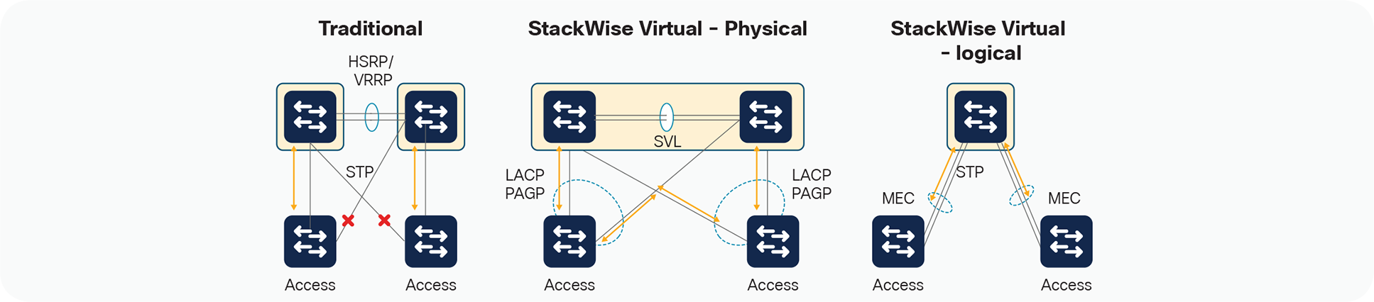
StackWise Virtual Benefits
A StackWise Virtual domain is created by converting two standalone Cisco Catalyst 9000 switches to a single logical network entity. The conversion is a one-time process that requires a few simple configuration steps and a system reload. After the reload, both devices come back online as StackWise Virtual Pair.
The StackWise Virtual domain is supported with specific hardware and software components, which are described later in this white paper
StackWise Virtual architecture
StackWise Virtual (SV) combines two switches into a single logical network entity from the network control plane and management perspectives. It uses Cisco IOS® Stateful Switchover (SSO) technology, as well as Non-Stop Forwarding (NSF) extensions to routing protocols, to provide seamless traffic failover when one of the device fails over. To neighboring devices, a StackWise Virtual domain appears as a single logical switch or router.
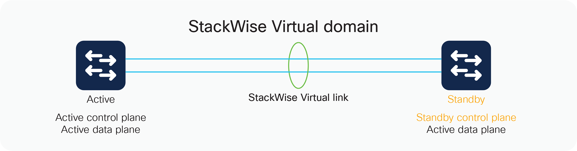
Within a StackWise Virtual domain, one device is designated as the SV active switch, and the other is designated as the SV standby switch (Figure 3). All control plane functions are centrally managed by the SV active switch, including:
● Management (Simple Network Management Protocol [SNMP], Telnet, Secure Shell [SSH] Protocol, etc.)
● Layer 2 protocols (Bridge Protocol Data Units [BPDUs], Protocol Data Units [PDUs], Link Aggregation Control Protocol [LACP], etc.)
● Layer 3 protocols (routing protocols, etc.)
● Software data path
Components of StackWise Virtual
From the data-plane and traffic-forwarding perspectives, both switches in a StackWise Virtual domain actively forward traffic. The active and standby switches support local forwarding that will individually perform the desired lookups and forward the traffic on local links to uplink neighbors. If the destination is on the other switch in the StackWise Virtual domain, ingress processing is performed on the ingress switch and then traffic is forwarded over the StackWise Virtual link to the egress switch where only egress processing is performed.
Centralized management
The fundamental design of a StackWise Virtual domain allows the centralized management of all network and device resources. This includes Layer 3 protocols such as Open Shortest Path First (OSPF), Enhanced Interior Gateway Routing Protocol (EIGRP), and Border Gateway Protocol (BGP), as well as Layer 2 protocols such as Spanning Tree Protocol (STP), Unidirectional Link Detection Protocol (UDLD), Flow Control, and LACP. A single switch in the StackWise Virtual domain is elected as the central management point for the entire system when accessed via management IP or console.
The switch acting as the single management point is referred to as the SV active switch. The peer chassis is referred to as the SV standby switch. The SV standby switch is also considered a hot-standby switch, since it is ready to become the active switch and take over all functions if something happens to the active switch. You can verify this setup with the following commands:
Stackwise-Virtual#show redundancy
Redundant System Information :
------------------------------
Available system uptime = 6 days, 2 hours, 41 minutes
Switchovers system experienced = 0
Standby failures = 0
Last switchover reason = none
Hardware Mode = Duplex
Configured Redundancy Mode = sso
Operating Redundancy Mode = sso
Maintenance Mode = Disabled
Communications = Up
Current Processor Information :
-------------------------------
Active Location = slot 1
Current Software state = ACTIVE
Uptime in current state = 6 days, 2 hours, 41 minutes
Image Version = Cisco IOS Software [Everest], Catalyst L3 Switch
Software (CAT9K_IOSXE), Version 16.6.2, RELEASE SOFTWARE (fc2)
Technical Support: http://www.cisco.com/techsupport
Copyright (c) 1986-2017 by Cisco Systems, Inc.
Compiled Wed 01-Nov-17 07:26 by mcpre
BOOT = flash:cat9k_iosxe.16.06.02.SPA.bin;
CONFIG_FILE =
Configuration register = 0x102
Peer Processor Information :
----------------------------
Standby Location = slot 2
Current Software state = STANDBY HOT
Uptime in current state = 6 days, 2 hours, 38 minutes
Image Version = Cisco IOS Software [Everest], Catalyst L3 Switch Software (CAT9K_IOSXE), Version 16.6.2, RELEASE SOFTWARE (fc2)
Technical Support: http://www.cisco.com/techsupport
Copyright (c) 1986-2017 by Cisco Systems, Inc.
Compiled Wed 01-Nov-17 07:26 by mcpre
BOOT = flash:cat9k_iosxe.16.06.02.SPA.bin;
CONFIG_FILE =
Configuration register = 0x102
StackWise Virtual MAC addresses
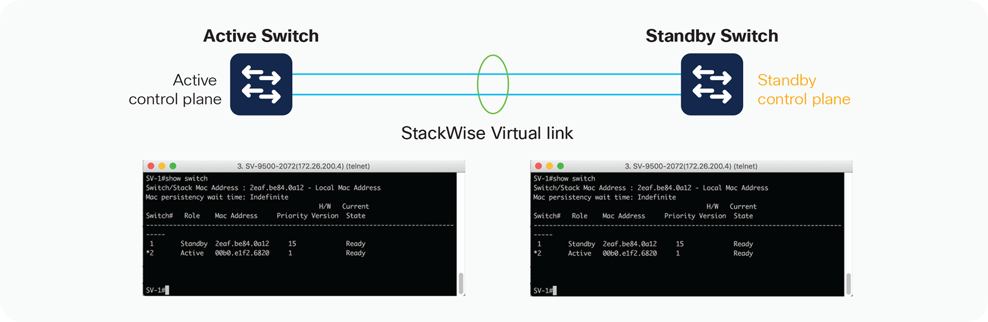
When a SV switch boots up and transitions to an active state, it assigns a MAC address to all its Layer 3 interfaces. From a default configuration, the MAC address is derived from an EEPROM memory device located on the Cisco Catalyst 9000 Switch itself. The switch that is elected to the active role will provide the system MAC address for the StackWise Virtual domain.
When the SV standby switch is brought online after StackWise Virtual activation, it also derives its switch MAC addresses from the MAC EEPROM of the active virtual switch. From this point onward, even if a switchover occurs between the virtual switches (causing a role change), the MAC address remains consistent, as shown in Figure 4. This is also shown in the output below the figure as “indefinite” in the MAC persistency wait time. This behavior especially helps in reducing the traffic impact, because the StackWise Virtual domain does not have to advertise a new MAC address to the neighbors during unexpected switchovers. You can modify this behavior by defining a specific time with “stack-mac persistent timer #,” which will typically update the MAC address of the system with the current active virtual switch within the configured time.
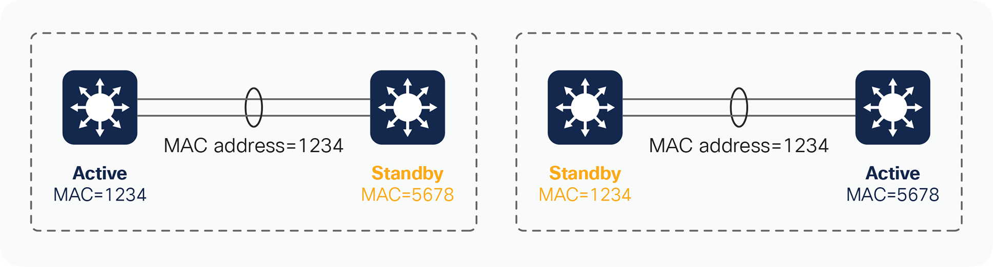
MAC address synchronization across a StackWise Virtual domain
SV-1#show switch
Switch/Stack Mac Address : 2eaf.be84.0a12 - Local Mac Address
Mac persistency wait time: Indefinite
H/W Current
Switch# Role Mac Address Priority Version State
-------------------------------------------------------------------------------------
1 Standby 2eaf.be84.0a12 15 Ready
*2 Active 00b0.e1f2.6820 1 Ready
If the entire StackWise Virtual domain is restarted and brought online again, and the peer switch or any other switch assumes the SV active role on activation, the virtual MAC address will then be derived from the new active switch. Consequently, the virtual MAC addresses will be different than they were before the system reload. In most environments, this change does not represent a problem, because gratuitous Address Resolution Protocol (ARP) frames advertising the new virtual MAC addresses are transmitted upon interface initialization.
If one of the switches in a StackWise Virtual domain fails completely with a hardware failure and happens to be the owner of the StackWise Virtual MAC address, the system will continue to function with the same MAC address unless the StackWise Virtual domain reloads or the user explicitly updates the stack MAC address. To update the MAC address on the StackWise virtual domain, execute the command “stack-mac update force.” This will update the stack MAC address with the current active virtual switch.
A StackWise Virtual domain consists of two Cisco Catalyst 9000 Switches. In order to bond the two switches together into a single logical node, special signaling and control information must be exchanged between the two switches in a timely manner. To facilitate this information exchange, a dedicated link is used to transfer both data and control traffic between the peer switches. This link is referred to as the StackWise Virtual link.
The StackWise Virtual link, formed as an EtherChannel interface, can comprise links ranging from one to eight physical member ports. These links carry two types of traffic: the StackWise Virtual control traffic and normal data traffic.
To make sure that control traffic gets highest priority across the StackWise Virtual link, a special bit is set on all of the link’s control frames. This helps ensure that these frames always get priority service on the egress hardware queues. From a data-plane perspective, the StackWise Virtual link is used to extend the internal switch data path to the neighboring switch. Data traffic sent on the StackWise Virtual link is load-balanced, using the configured EtherChannel load-balancing algorithms.
All frames that are sent across the StackWise Virtual link are encapsulated with a StackWise Virtual header, which is appended to the frame by the egress port Application-Specific Integrated Circuit (ASIC) and stripped off on the other side of the StackWise Virtual link by the ingress port ASIC. The header carries information such as the ingress port index, destination port index, VLAN, and Class of Service (CoS). The StackWise Virtual header is 64 bytes long. It is placed after the Ethernet preamble and directly before the Layer 2 header (Figure 5).
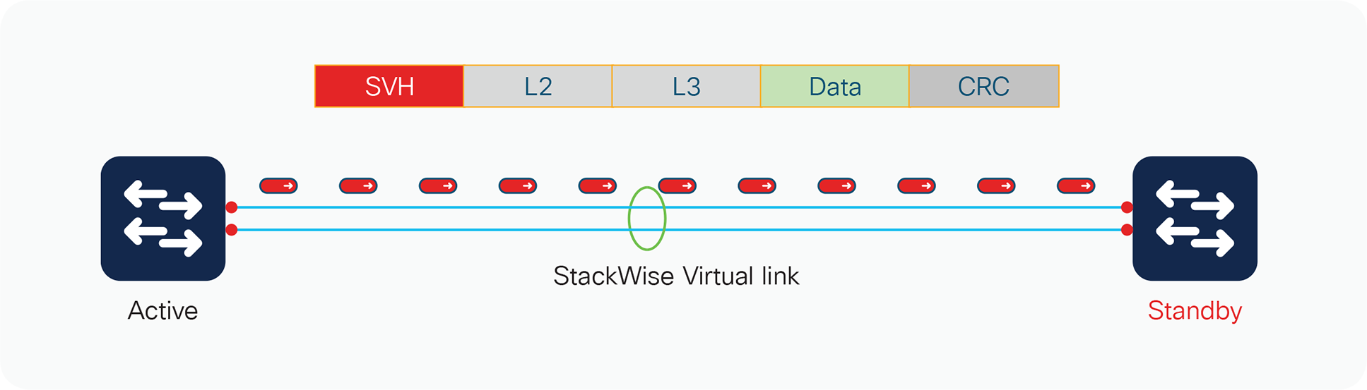
StackWise Virtual header
StackWise Virtual link initialization
The initialization process must determine which switch will become the active switch for the StackWise Virtual domain. To determine the active and standby roles, the StackWise Virtual link must be initialized and brought online for control plane communication. Because this determination affects the behavior of each switch, the roles must be negotiated very early during the switch bootup cycle. As a result, the system must bring the StackWise Virtual link and its associated ports online before initializing the rest of the system.
Communication between the two switches is facilitated with internal messaging that is sent across the StackWise Virtual link. Because the link is implemented as an EtherChannel interface, it is resilient to single-link failures.
The system must bring the StackWise Virtual link online before activating the StackWise Virtual domain. The initialization sequence consists of the steps shown in Figure 6.
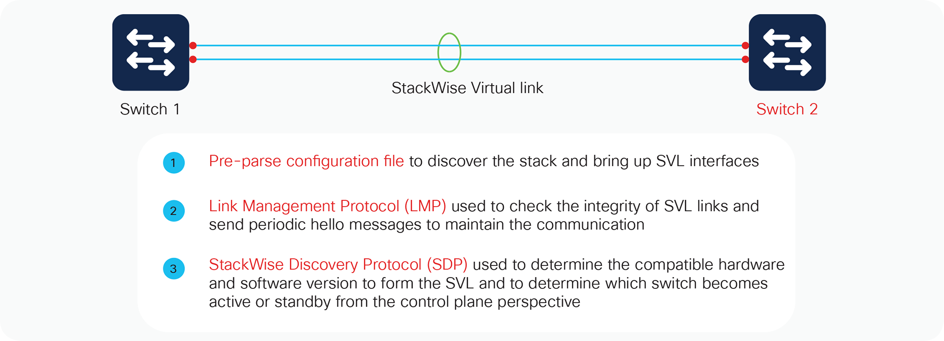
StackWise Virtual link initialization
Initialization
The switch determines which ports local to its system form members of the StackWise Virtual link, and the configuration file is pre-parsed to extract the appropriate StackWise Virtual link commands and their associated interfaces. This way, the link interfaces can quickly be brought online.
The Link Management Protocol (LMP) is activated on each link of the StackWise Virtual link as soon as it is brought up online. The LMP performs the following functions:
● Verifies link integrity by establishing bidirectional traffic forwarding, and rejects any unidirectional links
● Exchanges periodic hellos to monitor and maintain the health of the links
● Negotiates the version of StackWise Virtual header between the switches StackWise Virtual link role resolution
The redundancy role of each switch is resolved by the StackWise Discovery Protocol. This protocol performs the following functions:
● Determines whether the hardware and software versions allow a Cisco StackWise Virtual domain to be formed
● Determines which switch will become the active virtual switch and which will become the standby virtual switch from a control-plane perspective
High-availability role determination
During the role resolution, the active role is determined first, and only then does the other switch, which has a role of member, go through compatibility checks, followed by bulk configuration sync. The switch then transitions to the standby role by virtue of the SSO mechanism.
*Mar 1 01:41:05.532: %HA_CONFIG_SYNC-6-BULK_CFGSYNC_SUCCEED: Bulk Sync succeeded
*Mar 1 01:41:06.535: %RF-5-RF_TERMINAL_STATE: Terminal state reached for (SSO)
Hardware and software requirements
StackWise Virtual is supported on specific platforms with specific software releases in the catalyst 9000 family. Please refer to the respective software release notes and recommended release links before deploying them in production.
Each platform has its own specific requirements based on fixed or modular chassis when it comes to the configuration of StackWise Virtual Link and Dual-Active Detection Link. Prior to implementing StackWise Virtual, it is important to understand these requirements on each of the supported platforms.
StackWise Virtual is supported on all Cisco Catalyst 9500 Series Switches, some specific details are highlighted in Table 1 below.
StackWise Virtual is also supported on all Catalyst 9400 models - C9404, C9407 and C9410 chassis, with support of only single supervisor placed in the same slot number of both the StackWise virtual participating chassis. Catalyst 9400 can be deployed with all types of supervisor modules but SUP-1 module requires an additional License for StackWise virtual configuration. The in-chassis standby Supervisors if available will be powered-off by the system
during the StackWise Virtual conversion. In the event of failure, the failed supervisor has to be manually replaced. This limitation will be removed in the future software release. Table 1 Highlights some specific details around the support on Catalyst 9400 Models.
Table 1. StackWise Virtual requirements across various platforms
| Platform supported |
9500-16/40X |
9500-12Q/ 9500-24Q |
9404/9407/9410 SUP1/SUP1-XL/ SUP1-XL-Y** |
| StackWise Virtual links |
8 (All Downlink/Uplink ports) |
8 (All ports) |
8 (SUP ports)/ (10G ports on Linecards)* |
| Dual Active Detection DAD) links |
4 |
4 |
4 |
| Multi-Chassis Etherchannel |
128 |
128 |
252 |
StackWise Virtual Link Support on Line Cards: If the StackWise Virtual link is configured on Line cards, then all the supported ports on StackWise Virtual Active and Standby Supervisor Modules can be used for Uplink Connections.
StackWise Virtual is also supported on all Cisco Catalyst 9500 high performance models: C9500-24Y4C, C9500-48Y4C, C9500-32QC, C9500-32C.
Table 2 Highlights the hardware requirements for StackWise Virtual configuration across all the models
Table 2. StackWise Virtual requirements across all 9500-H models
| Platform supported |
C9500-32C |
C9500-32QC |
C9500-48Y4C |
C9500 -24Y4C |
| StackWise Virtual links |
Port 1-16* (40G/100G) |
Any port in default mode (40G/100G) |
Any port (Downlink: 10G/25G; Fixed Uplink: 40G/100G) |
Any port (Downlink: 10G/25G; Fixed Uplink: 40G/100G) |
| Dual Active Detection (DAD) links |
Port 1-16* (40G/100G) |
Any port in default mode (40G/100G) |
Any port (Downlink: 1G/10G/25G; Fixed Uplink: 40G/100G) |
Any port (Downlink: 1G/10G/25G; Fixed Uplink: 40G/100G) |
| Multi-Chassis Etherchannel |
128 |
128 |
128 |
128 |
Catalyst 9600 and quad supervisor support
StackWise Virtual is also supported on Catalyst 9606R model with the below specifications:
| Platform supported |
C9606R |
| StackWise Virtual links |
All Ports (10G/25G/40G/100G) |
| Dual Active Detection (DAD) links |
All ports (1G/10G/25G/40G/100G) |
| Multi-Chassis Etherchannel |
128 |
Quad-supervisor support with StackWise virtual
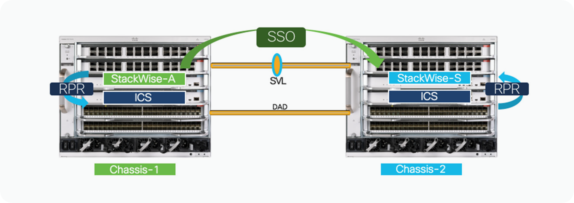
Beginning with Cisco IOS XE release 17.2.1, a catalyst 9600 switch configured with Supervisor 1 supports quad- supervisor Route Processor Redundancy (RPR) mode. This mode enhances the StackWise Virtual with support for Redundant Supervisor Module (RSM) within a single chassis. This functionality is also called In-Chassis Standby (ICS).
The two supervisor modules use RPR technology to establish an RPR cold-standby relationship within each local chassis, and Stateful Switchover (SSO) technology to establish an active/hot-standby redundancy relationship across the chassis. In the unlikely event that the active supervisor should fail within the chassis, the standby cold supervisor will transition to the active role (In-Chassis Active [ICA]). This transition occurs by fully booting up the ICS supervisor; it remains non-operational until the SSO redundancy is re-established with the new StackWise Virtual active supervisor across the chassis.
In RPR mode, the startup configuration is synchronized between the active and standby supervisors. The standby software is not fully initialized. Upon switchover, the standby supervisor becomes active automatically, but it must complete the boot process. In addition, all line cards are reloaded and the hardware is reprogrammed. The RPR switchover time is completed in few minutes
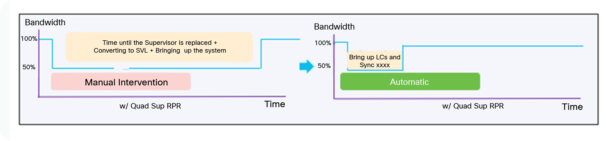
Key benefits of StackWise virtual quad sup RPR
When you support an in-chassis standby supervisor, the resiliency of the individual chassis increases, as well as the performance of the StackWise Virtual. During the event of StackWise Virtual Active Supervisor failure, the Standby Chassis will become the new active within a second based off SSO technology. The in-Chassis standby supervisor in failed chassis will fully boot up and re-initialize all the local line cards automatically without any human intervention leading to become the StackWise Virtual Standby Switch and this whole process is completed within few minutes.
StackWise virtual quad sup RPR – How it works
Catalyst 9600 StackWise Virtual supports Quad Supervisor RPR mode (Figure 1), where one of the supervisors in a given chassis would play a role of either SV-active or SV-standby, and another supervisor within the chassis would obtain a role of only in-chassis standby. As explained earlier, the ICS supervisor is not fully booted, but it does get the startup configuration from the ICA supervisor. The ICS supervisor in this case will load the image, run the Power-On Self-Test (POST) and loopback tests, and will wait for switchover. In due time, it not only becomes the local active supervisor; it also acquires the role of SV-standby when a peer is present. If a peer is not present, it assumes the role of SV-active.
Initialization process for SV quad sup RPR
When a SV-configured chassis powers up, and there are two supervisor modules installed in the chassis, each supervisor module will start its boot process. Very early on during this initialization process, the supervisor will determine two key factors: first, that it is a SV configuration, and second, that an in-chassis redundant supervisor module is installed in the same chassis. During the normal boot-up sequence, the supervisor module in the lower slot number will become the ICA, or the supervisor which is booted first will become the ICA and the other supervisor module will assume the ICS role.
Next, the ICA will continue the initialization process by attempting to establish communication over the StackWise Virtual Link (SVL) and negotiate a SSO redundancy across the chassis. Only the ICA supervisor from each chassis will participate in the SSO negotiation process. Based on the higher priority or lower mac-address, one of the ICA supervisor will become StackWise Virtual (SV) active and another as StackWise Virtual (SV) standby.
The ICS supervisor on both Chassis will load the image, run the POST and loopback tests, and will wait for switchover in RPR (cold-standby) mode.
Supervisor switchover in SW1 events
The failure of the SV-active supervisor causes an SSO switchover to the standby chassis. Other failures invoke either RPR switchover or no switchover at all. Table 2 shows the types of switchover against a supervisor failure.
Table 3. Type of Switchover Against a Supervisor Failure
| Supervisor Failure |
Type of Switchover |
| SW1 ICA fail |
●
SV-standby to SV-active - SSO
●
SW1 ICS to SW1 ICA - RPR
|
| SW1 ICS fail |
●
No switchovers; SW1 ICS reboots and comes back up as ICS in RPR mode
|
| SW2 ICA fail |
●
SW2 ICS becomes ICA maintaining the SV Standby Role- RPR
|
| SW2 ICS fail |
●
No switchovers; SW2 ICS reboots and comes back up as ICS in RPR mode
|
With inter-chassis SSO, the total switchover time is within a second and when a chassis fails or during a switchover event, all the links on that chassis go down. External switches that are single-homed into the failed chassis experience an outage. It is recommended to dual-home all connections to the SV pair using MEC technology, which primarily load-balances traffic across links, and keeps the traffic impact minimal in the event of chassis or link failure.
With intra-chassis RPR, all the line cards in the chassis are reset on switchover. After switchover, the ICS supervisor becomes ICA. If the failure is on SV active (SW1), the intra-chassis RPR switchover then triggers the inter-chassis SSO switchover and the SV-standby becomes the SV-active as part of the switchover event. ICS on SW1 upon complete boot up becomes the SV-standby after the SVL is established and the role is negotiated. If the supervisor failure is on the SV-standby chassis (SW2), the ICS supervisor becomes the new ICA after the intra-chassis RPR switchover, and eventually assumes the role of SV-standby.
Configuring and monitoring StackWise virtual quad sup RPR
From a configuration standpoint, no additional configuration commands are required to enable the SV quad sup RPR mode. The only requirement is that the supervisor modules run the same software image. When a second supervisor is inserted into an operational StackWise Virtual setup it should be either pre-loaded with the same image or should be upgraded to the same image as the active supervisor. Please refer to the installation/configuration guide below on the steps to upgrade the software on the new standby supervisor:
The SV Quad Sup RPR implementation creates some new file system names. The new names are based on the active/standby relationship. The new switch-number or slot-number naming convention allows the admin to reference a file system without consideration of the redundancy state of SV. Table 3 shows a subset of new file system names supported with the SV quad sup RPR implementation.
Table 4. Subset of File System Names Supported with a Quad Sup RRP Implementation
| File System Name |
Description |
| Bootflash: |
Bootflash on a SV active supervisor |
| Bootflash-1-1 |
Bootflash on an ICS supervisor of a SV active chassis |
| Bootflash-2-0 or stby-bootflash: |
Bootflash on a SV standby supervisor |
| Bootflash-2-1 |
Bootflash on an ICS supervisor of a SV standby chassis |
For viewing and monitoring the state of the individual supervisor modules, certain SV-related CLIs can be used to view the redundancy roles and states. An example of some important commands are shown below:
C9600#show switch
Switch/Stack Mac Address : 5c5a.c748.a600 - Local Mac Address
Mac persistency wait time: Indefinite
H/W Current
Switch# Role Mac Address Priority Version State
-----------------------------------------------
*1 Active 5c5a.c748.a600 0 V02 Ready
2 Standby 5c5a.c748.f100 0 V02 Ready
C9600#show module
Chassis Type: C9606R
Switch Number 1
Mod Ports Card Type Model Serial No.
---+-----+--------------------------
1 24 24-Port 40GE/12-Port 100GE C9600-LC-24C CAT2313L2VU
2 48 48-Port 10GE / 25GE C9600-LC-48YL CAT2310L57V
3 0 Supervisor 1 Module C9600-SUP-1 CAT2319L315
4 0 Supervisor 1 Module C9600-SUP-1 CAT2325L038
5 24 24-Port 40GE/12-Port 100GE C9600-LC-24C CAT2313L2VX
6 48 48-Port 10GE / 25GE C9600-LC-48YL CAT2312L2GK
Mod MAC addresses Hw Fw Sw Status
---+-----------------------------
1 DC8C.37C9.B900 to DC8C.37C9.B97F 1.0 17.1.1[FC2] 17.02.01 ok
2 DC8C.3772.DE80 to DC8C.3772.DEFF 1.0 17.1.1[FC2] 17.02.01 ok
3 5C5A.C748.A600 to 5C5A.C748.A67F 1.0 17.1.1[FC2] 17.02.01 ok
4 -- -- -- -- Provisioned
5 DC8C.37C9.B380 to DC8C.37C9.B3FF 1.0 17.1.1[FC2] 17.02.01 ok
6 DC8C.37A0.6300 to DC8C.37A0.637F 1.0 17.1.1[FC2] 17.02.01 ok
Mod Redundancy Role Operating Redundancy Mode Configured Redundancy Mode
---+-------------------+-------------------------+-----------------------
3 Active sso sso
4 InChassis-Standby rpr rpr
Switch Number 2
Mod Ports Card Type Model Serial No.
---+-----+--------------------------
1 24 24-Port 40GE/12-Port 100GE C9600-LC-24C CAT2313L2W2
2 48 48-Port 10GE / 25GE C9600-LC-48YL CAT2310L573
3 0 Supervisor 1 Module C9600-SUP-1 CAT2325L006
4 0 Supervisor 1 Module C9600-SUP-1 CAT2325L03A
5 24 24-Port 40GE/12-Port 100GE C9600-LC-24C CAT2310L4DD
6 48 48-Port 10GE / 25GE C9600-LC-48YL CAT2310L5AL
Mod MAC addresses Hw Fw Sw Status
---+-----------------------------
1 DC8C.37C9.B780 to DC8C.37C9.B7FF 1.0 17.1.1[FC2] 17.02.01 ok
2 DC8C.3772.D680 to DC8C.3772.D6FF 1.0 17.1.1[FC2] 17.02.01 ok
3 -- -- -- -- Provisioned
4 5C5A.C748.F100 to 5C5A.C748.F17F 1.0 17.1.1[FC2] 17.02.01 ok
5 DC8C.37A0.2800 to DC8C.37A0.287F 1.0 17.1.1[FC2] 17.02.01 ok
6 DC8C.37A0.1A80 to DC8C.37A0.1AFF 1.0 17.1.1[FC2] 17.02.01 ok
Mod Redundancy Role Operating Redundancy Mode Configured Redundancy Mode
---+-------------------+-------------------------+----------------------
3 InChassis-Standby rpr rpr
4 Standby sso sso
Chassis 1 MAC address range: 64 addresses from 2c4f.5204.dd80 to 2c4f.5204.ddbf
Chassis 2 MAC address range: 64 addresses from 2c4f.5204.f240 to 2c4f.5204.f27f
C9600#show redundancy rpr
My Switch Id = 1
Peer Switch Id = 2
Last switchover reason = none
Configured Redundancy Mode = sso
Operating Redundancy Mode = sso
Switch 1 Slot 3 Processor Information:
--------------------------------------
Current Software State = ACTIVE
Uptime in current state = 1 week, 6 days, 4 hours, 16 minutes
Image Version = Cisco IOS Software [Amsterdam], Catalyst L3 Switch Software (CAT9K_IOSXE), Version 17.2.1, RELEASE SOFTWARE (fc4)
Technical Support: http://www.cisco.com/techsupport
Copyright (c) 1986-2020 by Cisco Systems, Inc.
Compiled Thu 26-Mar-20 03:29 by mcpre
BOOT = bootflash:packages.conf;
Switch 1 Slot 4 Processor Information:
--------------------------------------
Current Software State = InChassis-Standby (Ready)
Uptime in current state = 1 week, 6 days, 4 hours, 16 minutes Image Version =
BOOT = bootflash:packages.conf;
Switch 2 Slot 4 Processor Information:
--------------------------------------
Current Software State = STANDBY HOT
Uptime in current state = 21 hours, 19 minutes
Image Version = Cisco IOS Software [Amsterdam], Catalyst L3 Switch Software (CAT9K_IOSXE), Version 17.2.1, RELEASE SOFTWARE (fc4)
Technical Support: http://www.cisco.com/techsupport
Copyright (c) 1986-2020 by Cisco Systems, Inc.
Compiled Thu 26-Mar-20 03:29 by mcpre
BOOT = bootflash:packages.conf;
Switch 2 Slot 3 Processor Information:
--------------------------------------
Current Software State = InChassis-Standby (Ready)
Uptime in current state = 21 hours, 17 minutes
Image Version =
BOOT = bootflash:packages.conf;
Note: Breakout is not supported for StackWise Virtual and DAD links across all platforms but QSA (10G) is supported for SVL and DAD links on 9500H/9600 platforms.
Note: StackWise Virtual is supported on all Catalyst 9k Platforms with Network Advantage License only
StackWise Virtual link redundancy
The StackWise Virtual link is clearly a vital part of the StackWise Virtual domain. It provides the signaling path used for synchronizing the two switch control planes, as well as the data path for any user data traffic needing to pass between the two switches. Therefore, the StackWise Virtual link is bundled as an EtherChannel interface, allowing for redundant interfaces and higher bandwidth capacity.
Given the hardware requirements discussed in the architecture section of this paper, the StackWise Virtual link must be configured using either 10 Gigabit or 40 Gigabit Ethernet ports. And it is very important that you have enough redundancy and bandwidth available to overcome the unexpected failure scenarios described below.
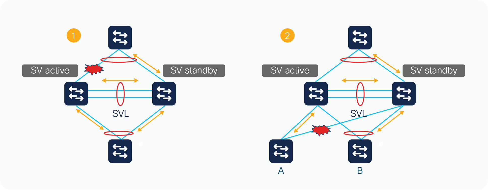
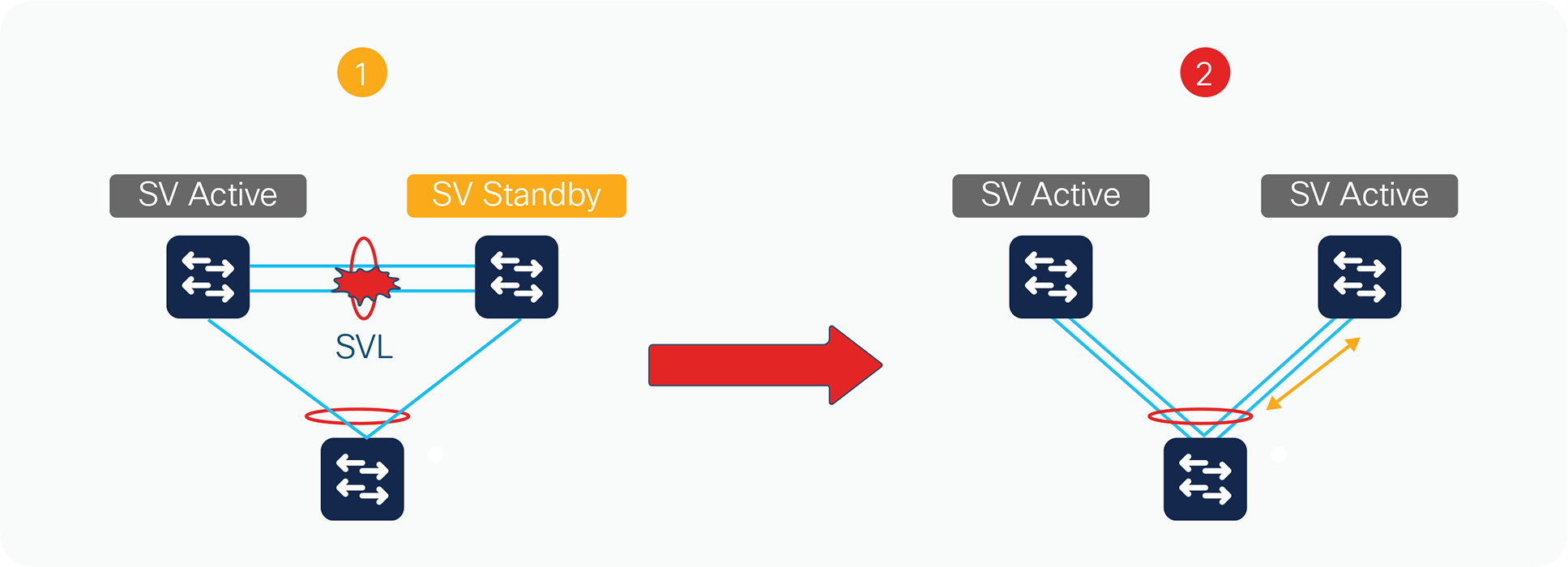
Two failure scenarios
Figure 6 shows two failure scenarios. In Scenario 1, if all the uplinks on either of the StackWise Virtual switches fails, the traffic destined toward the uplinks will start traversing through the StackWise Virtual link toward the neighboring switch in order to reach the destination. In Scenario 2, if there is traffic destined from ‘B’ to ‘A’ with traffic always being hashed to SV Standby Switch and a link failure occurs in the Multichassis EtherChannel (MEC) making switch ‘A’ connection as single homed, the traffic will have to use the StackWise Virtual link to reach the destination. In addition to these scenarios, if a span capture is enabled for a source on one switch and a destination on another switch or, for multicast applications, with members and source on different switches, the StackWise Virtual link will be heavily leveraged. Therefore, it is very important for it to have enough bandwidth to account for these scenarios and also enough redundancy to service all the user traffic in case one of the links fails.
Multiple StackWise Virtual domains
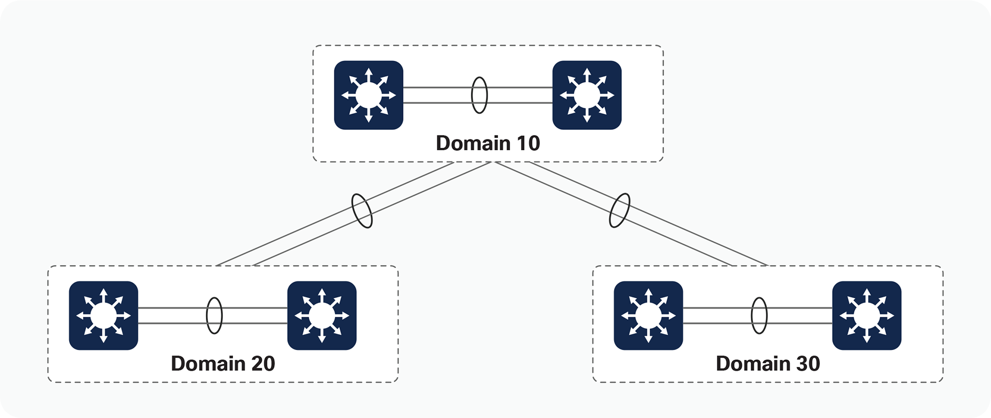
Multiple deployments of StackWise Virtual can exist in a given network design, adding to the availability and scalability of the network. As a result, Cisco requires that you use unique virtual switch domain identifiers for each pair of StackWise Virtual switches.
Figure 8 shows an example of multiple Cisco StackWise Virtual domains in a network design. The figure shows three unique StackWise Virtual domains, each with a unique domain ID. You can also deploy multichassis EtherChannel links across other StackWise Virtual domains, removing the reliance on protocols such as Spanning Tree Protocol.
Multiple StackWise Virtual domains
Another example of multiple StackWise Virtual domains is in the area of adjacent Layer 2 WAN deployments. A routed Layer 3 WAN connection may not be possible due to business or application requirements, requiring a Layer 2 connection between two disparate geographic sites that still provides link redundancy. This will ultimately require the implementation of some form of Layer 2 redundancy protocol (such as Spanning Tree Protocol), resulting in complex topologies as well as inefficient bandwidth utilization across network links. The use of StackWise Virtual will mitigate such inefficiencies through the formation of multichassis EtherChannel connections.
EtherChannel interfaces on the Cisco Catalyst 9000 platform represent a grouping of one or more physical ports into a single logical port from the perspective of either a Layer 2 switching or Layer 3 routing environment. EtherChannel interfaces allow for individual link resiliency and also provide added bandwidth without the necessity of complex protocols.
There are generally no restrictions with regard to which ports can form members of an EtherChannel link, except that the member interfaces need to be of the same speed and no more than eight members can belong to a single EtherChannel grouping. You can, therefore, extend members of the EtherChannel interface across switching ASICs to allow for maximum availability of the EtherChannel interface if a single link fails.
Traffic distribution and hashing
The distribution of traffic across the various members of the EtherChannel link is accomplished through different hash schemes, each using a fixed set of fields within the frame to determine which EtherChannel member is used to forward a particular traffic flow. You can choose from 13 different hash schemes:
SVL(config)#port-channel load-balance ?
dst-ip Dst IP Addr
dst-mac Dst Mac Addr
dst-mixed-ip-port Dst IP Addr and TCP/UDP Port
dst-port Dst TCP/UDP Port
mpls Load Balancing for MPLS packets
src-dst-ip Src XOR Dst IP Addr
src-dst-mac Src XOR Dst Mac Addr
src-dst-mixed-ip-port Src XOR Dst IP Addr and TCP/UDP Port
src-dst-port Src XOR Dst TCP/UDP Port
src-ip Src IP Addr src-mac Src Mac Addr
src-mixed-ip-port Src IP Addr and TCP/UDP Port src-port
Src TCP/UDP Port
Selection of the hash scheme of choice largely depends on the traffic mix through the EtherChannel interface, noting that these hash schemes may be selected only on a global basis.
Multichassis EtherChannel links
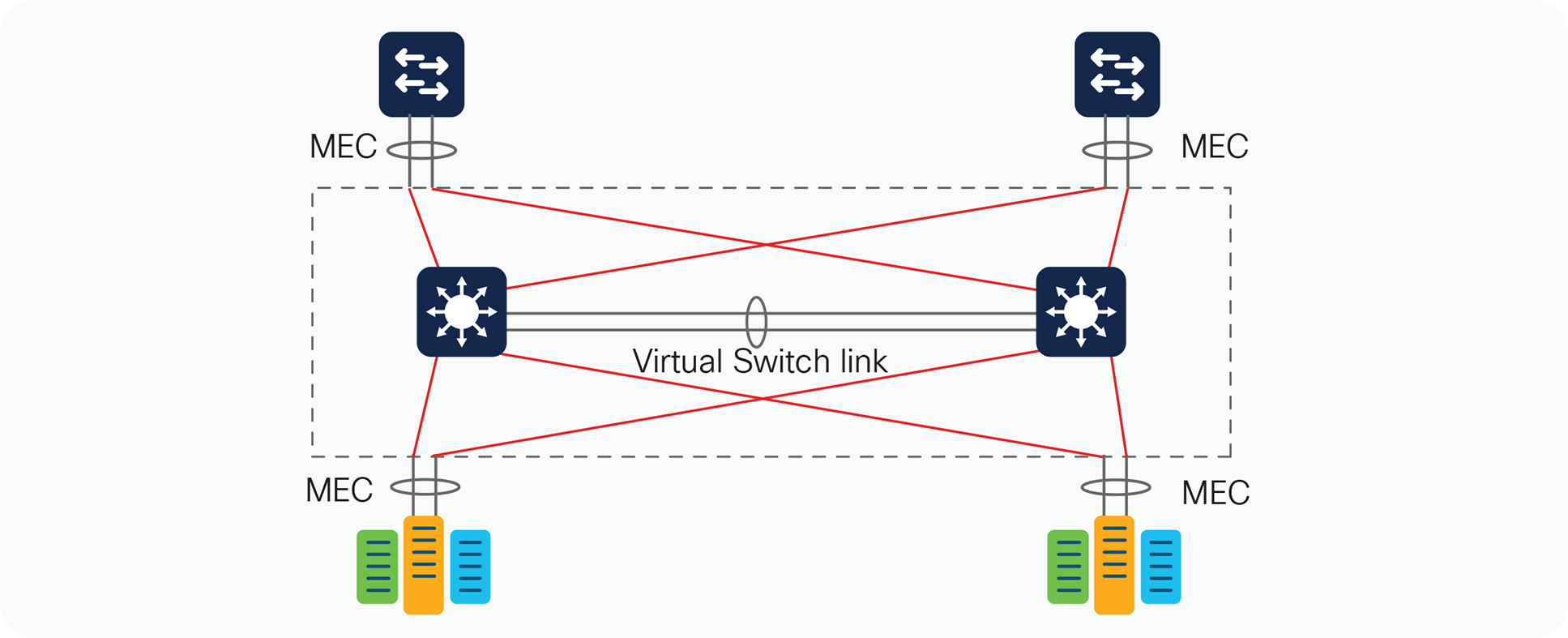
The multichassis EtherChannel interface spans more than a single physical switch (Figure 9). StackWise Virtual allows the formation of this multichassis EtherChannel link. It also allows the dual-homed connections to and from the upstream and downstream devices to be configured as EtherChannel links, as opposed to individual links. As a result, multichassis EtherChannel links allow for implementation of new network designs in which true Layer 2 multipathing can be implemented, without relying on Layer 2 redundancy protocols such as Spanning Tree Protocol. StackWise Virtual currently supports 128 EtherChannel links.
Multichassis EtherChannel links
Like regular EtherChannel interfaces, all ports within the multichassis EtherChannel link have the same source index, regardless of the chassis in which they are physically present. This makes it possible to apply a single IP address for Layer 3 EtherChannel links or for Spanning Tree Protocol to view an EtherChannel interface as a single logical port.
One unique difference between multichassis EtherChannel and regular EtherChannel interfaces is the way traffic is load-balanced across the channel group members. A regular EtherChannel link selects the appropriate channel group member to exit based purely on the hashing algorithm of choice. A multichassis EtherChannel link, however, has some extra intelligence to reduce the amount of traffic that requires transmission across the StackWise Virtual link. This optimization is accomplished by populating the index port only with the ports local to the physical switch. This allows the switch to favor the local ports of the multichassis EtherChannel link over those on the remote switch.
For traffic that must be flooded on the VLAN (broadcasts, multicasts, and unknown unicasts), a copy is sent across the StackWise Virtual link to be sent out to any single-homed ports belonging to the VLAN. Because the first switch will have sent a copy to one of the multichassis EtherChannel ports, packets received from the StackWise Virtual link are not sent out of another multichassis EtherChannel port. If all of the multichassis EtherChannel ports on a given switch are removed because of a failure, management control, or other issue, the EtherChannel link is no longer a multichassis EtherChannel link. Instead it becomes a regular EtherChannel link, and hence flooded packets will be sent out of this EtherChannel link from the StackWise Virtual link.
Although the data traffic is spread across the two switches, the SV active switch must terminate control traffic for the multichassis EtherChannel link, including most of the Layer 2 protocols such as Spanning Tree Protocol, Port Aggregation Protocol (PAgP), VLAN Trunking Protocol (VTP), etc. All multichassis EtherChannel links have their control protocols terminated on the SV active switch. Any control protocols received by multichassis EtherChannel link ports on the SV standby switch are redirected to the SV active switch through the StackWise Virtual link. Because the EtherChannel link is terminated in one switch, PAgP and LACP have the same device identifier on all the member links, regardless of the switch on which the link resides.
Multichassis EtherChannel link management protocols
Multichassis EtherChannel links support default mode “on”, PAgP and LACP, which run on the SV active switch. Protocol frames that the SV standby switch receives are relayed to the active switch through the StackWise Virtual link.
The default configuration is for the individual switch to operate in standalone mode. In order to migrate to StackWise Virtual mode, you must perform a conversion procedure as follows.
After the switch reloads and is operating in StackWise Virtual mode, it begins the StackWise Virtual initialization sequence. Additionally, the switch and interface naming convention is changed to allow for the specification of a switch identifier as part of the interface name. Please refer to the section “Operational Management” for more information.
Switch identifier
Each switch within a StackWise Virtual domain is allocated a unique switch identifier upon conversion to SV mode. This identifier is known as the switch identifier, or switch ID. This number is used as part of the interface naming, to help ensure that the interface name remains the same regardless of the active or standby switch roles.
Conversion to StackWise Virtual mode
This section details the steps required to convert a standalone system into a StackWise Virtual domain. The interfaces forming the StackWise Virtual link should be connected before the conversion process, to minimize the number of times the switch is reloaded.
Figure 10 depicts the conversion process.
StackWise Virtual conversion
Step 1. Configure the StackWise Virtual domain.
| On the two switches, configure the same virtual switch domain number (in this case it is 100) SV-1#conf t Enter configuration commands, one per line. End with CNTL/Z. SV-1(config)#stackwise-virtual Please reload the switch for StackWise Virtual configuration to take effect SV-1(config-stackwise-virtual)#domain 100 |
SV-2#conf t Enter configuration commands, one per line. End with CNTL/Z. SV-2(config)#stackwise-virtual Please reload the switch for StackWise Virtual configuration to take effect SV-2(config-stackwise-virtual)#domain 100 |
Step 2. Configure the StackWise Virtual link.
By default in standalone mode, the switches are identified with switch 1 unless explicitly changed to some other switch number. During the conversion to StackWise Virtual, the switch numbers are changed automatically to reflect two switches in the StackWise Virtual domain.
| SV-1#conf t Enter configuration commands, one per line. End with CNTL/Z. SV-1(config)#interface range fortyGigabitEthernet 1/0/23-24 SV-1(config-if-range)#stackwise-virtual link 1 WARNING: All the extraneous configurations will be removed for FortyGigabitEthernet1/0/23 on reboot WARNING: All the extraneous configurations will be removed for FortyGigabitEthernet1/0/24 on reboot SV-1(config-if-range)#end |
SV-1#conf t Enter configuration commands, one per line. End with CNTL/Z. SV-2(config)#interface range fortyGigabitEthernet 1/0/23-24 SV-2(config-if-range)#stackwise-virtual link 1 WARNING: All the extraneous configurations will be removed for FortyGigabitEthernet1/0/23 on reboot WARNING: All the extraneous configurations will be removed for FortyGigabitEthernet1/0/24 on reboot SV-2(config-if-range)#end |
After the “stackwise-virtual link” command is executed on the range of ports, the switch will automatically bundle the links to form a port channel. You do not need to configure a port channel or specify a protocol; the switch will automatically create a port channel with internal protocol.
Step 3. Configure StackWise Virtual dual-active detection – This has to be configured on a different port than the StackWise Virtual link ports.
| SV-1(config)#interface fortyGigabitEthernet 1/0/12 SV-1(config-if)#stackwise-virtual dual-active-detection WARNING: All the extraneous configurations will be removed for FortyGigabitEthernet1/0/12 on reboot. SV-1(config-if)#end |
SV-2(config)#interface fortyGigabitEthernet 1/0/12 SV-2(config-if)#stackwise-virtual dual-active-detection WARNING: All the extraneous configurations will be removed for FortyGigabitEthernet1/0/12 on reboot. SV-1(config-if)#end |
Step 4. Save the configuration and reload the switch
This step will convert the standalone switches to the StackWise Virtual domain once they come back online after the reload.
| SV-1#wr mem Building configuration... [OK] SV-1#reload Reload command is being issued on Active unit, this will reload the whole stack Proceed with reload? [confirm] # Hit Enter here to proceed with the reload |
SV-2#wr mem Building configuration... [OK] SV-2#reload Reload command is being issued on Active unit, this will reload the whole stack Proceed with reload? [confirm] # Hit Enter here to proceed with the reload |
During the reload of the switches:
The startup and running configurations of both switches are combined and based on active or standby election. The first switch to boot up, or the active virtual switch, is assigned switch identifier 1, and the second switch, or the standby virtual switch, is assigned switch identifier 2. The interface numbers will also reflect the switch number in their outputs.
When the two switches are brought online, they proceed with StackWise Virtual link initialization and initialize their respective StackWise Virtual link ports. The two switches communicate with each other and determine active and standby roles. This exchange of information is evident through the following console messages:
| *Mar 1 23:58:27.791: %IOSXE_REDUNDANCY-6-PEER: Active detected switch 2 as standby. *Mar 1 23:58:27.790: %STACKMGR-6-STANDBY_ELECTED: Switch 1 R0/0: stack_mgr: Switch 2 has been elected STANDBY. *Mar 1 23:58:47.829: %REDUNDANCY-5-PEER_MONITOR_EVENT: Active detected a standby insertion (raw-event=PEER_FOUND(4)) *Mar 1 23:58:47.829: %REDUNDANCY-5-PEER_MONITOR_EVENT: Active detected a standby insertion (raw-event=PEER_REDUNDANCY_STATE_CHANGE(5)) *Mar 1 23:59:22.369: %HA_CONFIG_SYNC-6-BULK_CFGSYNC_SUCCEED: Bulk Sync succeeded *Mar 1 23:59:23.371: %RF-5-RF_TERMINAL_STATE: Terminal state reached for (SSO) |
After the StackWise Virtual link is initialized and the StackWise Virtual domain becomes active, you may notice that the console or the management access to both the active and standby switches will take you to a single logical switch, which is the active one.
| SV-1#show switch Switch/Stack Mac Address : 00a3.d145.2300 - Local Mac Address Mac persistency wait time: Indefinite H/W Current Switch# Role Mac Address Priority Version State ---------------------------------------- ---------------------------------------- ----- *1 Active 00a3.d145.2300 15 V01 Ready 2 Active 00a3.d145.1e00 14 V01 Ready |
SV-1#show switch Switch/Stack Mac Address : 00a3.d145.2300 - Local Mac Address Mac persistency wait time: Indefinite H/W Current Switch# Role Mac Address Priority Version State ---------------------------------------- ---------------------------------------- ----- *1 Standby 00a3.d145.2300 15 V01 Ready 2 Standby 00a3.d145.1e00 14 V01 Ready |
With the following command you can determine that the StackWise Virtual domain is now operating and that the two switches are acting as a single logical network node.
SV-1#show switch
Switch/Stack Mac Address : 00a3.d145.0100 - Local Mac Address
Mac persistency wait time: Indefinite
H/W Current
Switch# Role Mac Address Priority Version State
-------------------------------------------------------------------------------------
*1 Active 00a3.d145.0100 15 V01 Ready
2 Standby 00a3.d145.2200 14 V01 Ready
Management of the system as a whole changed with the advent of StackWise Virtual. The fundamental concept of a switching system has evolved from a single physical entity managed separately to multiple physical entities that are managed as a single system. The following section examines areas such as console management, in-band (Telnet or SSH) management, SNMP and MIB changes, effects of NVRAM, NetFlow features, Switch Port Analyzer (SPAN), and Embedded Event Manager (EEM).
After the two individual switches are converted into a StackWise Virtual domain, console access to the active or standby switch will log in to the single StackWise Virtual switch, from where you can handle all configuration, monitoring, and troubleshooting for both switches under a single interface. The console output for the standby switch is the same as for the active switch console, as shown in Figure 11.
Active and standby consoles
If a switchover occurs and switch 2 becomes the active virtual switch, the console access will still be the same for both switches.
Interface numbering
After conversion to a StackWise Virtual domain, the interface numbering scheme does not change, but both the active and standby switch interfaces reflect the switch number in the interface numbering:
<INTERFACE_TYPE> <SWITCH_ID>/<MODULE>/<PORT>
| SV-1#show interfaces status Port Fo1/0/1 Fo1/0/2 Fo1/0/3 Fo1/0/4 Fo2/0/1 Fo2/0/2 Fo2/0/3 Fo2/0/4 |
Reloading the StackWise Virtual domain and its members
It may sometimes be desirable to reload the entire system or to reset individual members of the StackWise Virtual domain. You can perform these tasks through the console of the active switch.
Reloading the StackWise Virtual domain
If you need to reload the entire StackWise Virtual domain (both active and standby switch), use the following command:
SV-1#reload
Proceed with rel
SV-1#redundancy force-switchover
This will reload the active unit and force a switchover to standby.[confirm]
Preparing for switchover.
You also have two options to reset the SV standby switch. First, you can use the same command as before, replacing the switch ID with the switch ID of the standby switch or you can use the below command:
SV-1#reload standby-cpu
Stack is in Half ring setup; Reloading a switch might cause stack split
Proceed with reload? Y/N[confirm]Y
Alternatively, use the command redundancy reload peer to reload the standby virtual switch:
SV-1#redundancy reload peer
Reload peer [confirm]
Preparing to reload peer
Central to the high-availability model of a StackWise Virtual domain are the concepts of NSF and SSO. The intricacies of these protocols are beyond the scope of this paper; you can find more information on them in the Cisco Catalyst switching documentation on the Cisco website.
The high-availability model of the system changes when you integrate two switches together into a single network entity. To take advantage of the existing innovations in NSF and SSO technologies, StackWise Virtual has implemented a high-availability model that uses this redundancy framework for an interchassis environment (Figure 12).
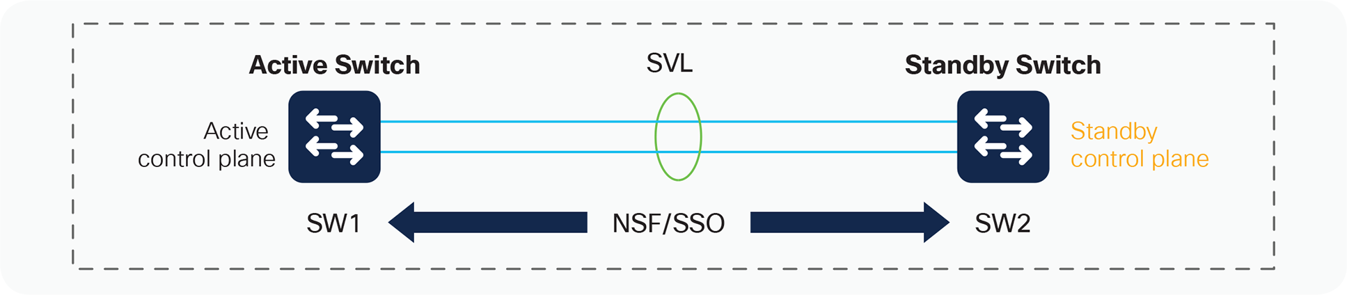
Interchassis NSF and SSO in a StackWise Virtual environment
In an SSO system, “high-availability-aware” protocols and features may synchronize events and state information from the active switch to the hot-standby switch. From a redundancy framework viewpoint, the active switch acts as a server, whereas the standby switch acts as the client. Information that is “high availability aware” will be statefully synchronized between these entities. In the event of a failover, the standby switch does not need to relearn this information, reducing the outage time.
As Figure 12 shows, the primary switch (switch 1 in the figure) assumes the active role, whereas the secondary switch (switch 2) assumes the hot-standby role. You can verify this situation with the following command:
SV-1#show redundancy
Redundant System Information :
------------------------------
Available system uptime = 3 hours, 31 minutes
Switchovers system experienced = 0
Standby failures = 1
Last switchover reason = none
Hardware Mode = Duplex
Configured Redundancy Mode = sso
Operating Redundancy Mode = sso
Maintenance Mode = Disabled
Communications = Up
Current Processor Information :
-------------------------------
Active Location = slot 1
Current Software state = ACTIVE
Uptime in current state = 3 hours, 31 minutes
Image Version = Cisco IOS Software [Everest], Catalyst L3 Switch Software (CAT9K_IOSXE), Version 16.6.2, RELEASE SOFTWARE (fc2)
Technical Support: http://www.cisco.com/techsupport
Copyright (c) 1986-2017 by Cisco Systems, Inc.
Compiled Wed 01-Nov-17 07:26 by mcpre
BOOT = flash:cat9k_iosxe.16.06.02.SPA.bin;
CONFIG_FILE =
Configuration register = 0x102
Peer Processor Information :
----------------------------
Standby Location = slot 2
Current Software state = STANDBY HOT
Uptime in current state = 17 minutes
Image Version = Cisco IOS Software [Everest], Catalyst L3 Switch Software (CAT9K_IOSXE), Version 16.6.2, RELEASE SOFTWARE (fc2)
Technical Support: http://www.cisco.com/techsupport
Copyright (c) 1986-2017 by Cisco Systems, Inc.
Compiled Wed 01-Nov-17 07:26 by mcpre
BOOT = flash:cat9k_iosxe.16.06.02.SPA.bin;
CONFIG_FILE =
Configuration register = 0x102
As this output indicates, if a failure occurs in the active virtual switch, an SSO switchover is invoked, and the hot-standby switch assumes the role of the active switch for the StackWise Virtual domain. This switchover should take approximately 50 ms.
Synchronizing configurations
When the redundancy-framework progression between the SV active and SV standby switch is reached, the configurations of the two switches are synchronized. The configuration file contains the configuration for the entire StackWise Virtual domain, and it overwrites the configuration that exists on the SV standby switch. Both the bulk configuration synchronization and the incremental configuration synchronization is sent through internal control messages across the StackWise Virtual link. As a result, the configuration in the SV standby switch NVRAM is overwritten.
Virtual switch priorities and switch preemption
Because the StackWise Virtual domain consists of two switches merged into a single entity, you can designate a particular physical switch to prefer an active role, while its peer prefers the standby role. By default, this designation is usually determined as follows:
If the switches are initiated at different times, the switch that is initiated first becomes the active virtual switch. If the switches are initiated simultaneously, the switch with the lower MAC address becomes the active virtual switch.
You can alter the default behavior by using the Switch Priorities feature.
Switch priorities and preemption
Switch priorities are assigned to each member of the StackWise Virtual domain under the Privilege Exec mode. By influencing the weighting of the priorities of each switch, you can deterministically define which physical switch will prefer the SV active role or the SV standby role.
A sample configuration follows:
SV-1# switch 1 priority 15
WARNING: Changing the switch priority may result in a configuration change for that switch. Do you want to continue?[y/n]? [yes]:
# The switch with highest priority will always become active Switch
SV-2# switch 2 priority 14
WARNING: Changing the switch priority may result in a configuration change for that switch. Do you want to continue?[y/n]? [yes]:
StackWise Virtual does not support preemption capability to avoid unnecessary traffic disruption. If you need to change the StackWise Virtual role to another switch, the “redundancy force-switchover” command can be used for that purpose. This will move the active role to the other switch with very minimal traffic disruption.
Traffic forwarding
Cisco StackWise Virtual supports the concept of local forwarding when it comes to handling Unicast or Broadcast, Unknown Unicast and Multicast (BUM) Traffic. Local forwarding is a concept where the traffic is forwarded locally towards the destination by both Active and Standby switches on its interfaces rather than forwarding it to the neighboring switch over the StackWise Virtual Links. Traffic will be forwarded over the StackWise Virtual Links only if there is a single homed connection and hence it is always recommended to use the dual homed connections to avoid unnecessary traffic over the SVL. Below diagram gives a pictorial representation of traffic handling in the StackWise Virtual Setup:
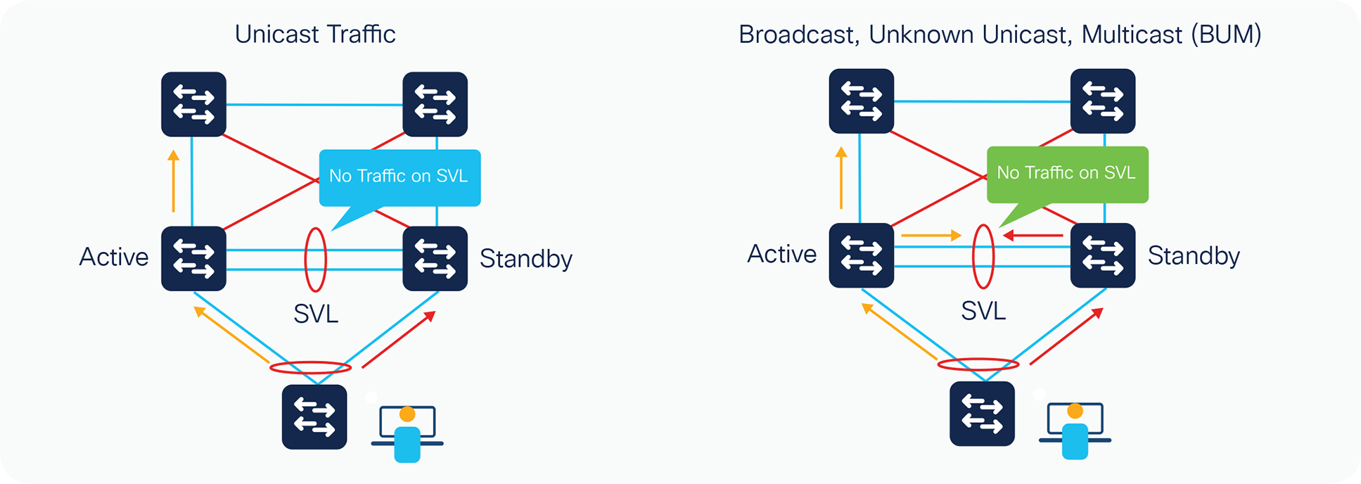
Local forwarding support with BUM traffic has been introduced with 17.2 release but the unicast traffic support has been there for a while.
Failure scenarios
When the StackWise Virtual link is operating under normal, nonfailure scenarios, both switches are actively forwarding data traffic, while one of the switches has negotiated to become the active control plane.
Active switch failure
The SV standby switch can detect the failure of the SV active switch using one of the following methods:
● Redundancy framework heartbeats sent across the StackWise Virtual link
● StackWise discovery protocol
● Cisco Generic Online Diagnostics (GOLD) failure event
● Full StackWise Virtual link down
Upon detecting the failure of the active switch, the hot-standby switch performs an SSO switchover and assumes the role of the active switch.
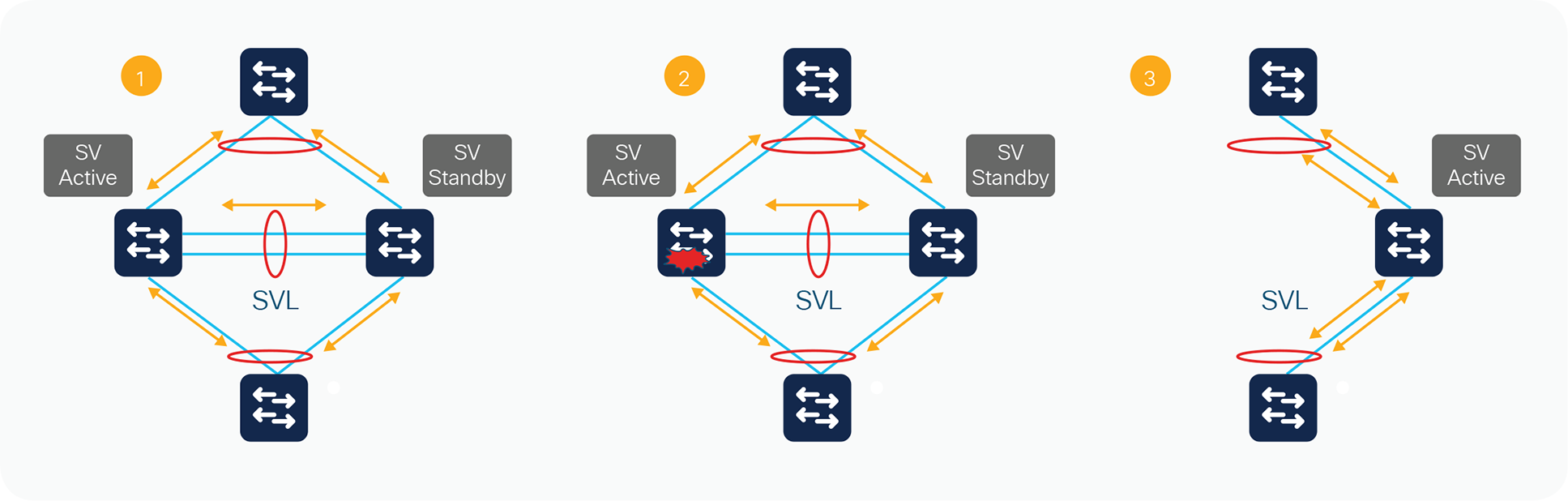
Three main stages of a switchover event
The effect on the data path is illustrated in Figure 13, using three main stages. In Stage 1, the StackWise Virtual switch is operating under normal conditions with no failures. In Stage 2, the active switch fails. At this time, the standby switch transitions to the active role. Stage 3 depicts all of the traffic transitioned to the new active switch
During the transition, there is a disruption to the traffic that must transition away from the failed switch. The duration of this disruption is determined by the time required to transition the hot-standby switch to the role of active switch, and for the neighboring device to modify its path selection to the newly active switch. If the vast majority of interfaces in the StackWise Virtual domain are multichassis EtherChannel links, this data disruption should have minimal effect on the network, and the disruption will be in sub-seconds. Packets that are handled in the software path, however, will experience a slightly longer disruption. This failover should be similar to a typical SSO failure.
Hot-standby switch failure
The SV active switch can detect the failure of the hot-standby switch in the following ways:
● Redundancy framework heartbeats sent across the StackWise Virtual link by the active switch
● Full StackWise Virtual link-down situation
● Cisco Generic Online Diagnostics (GOLD) failure event
Upon detecting the failure of the hot-standby switch, the active switch simulates an online insertion and removal (OIR) event for the SV standby switch. Assuming that adjacent devices are dual-homed to both the active and standby switches, only those flows being forwarded through the SV standby switch are nominally affected until all the traffic converges to the active switch. The overall bandwidth of the StackWise Virtual system is reduced by half, but there is no impact on the original traffic flowing through the active switch.
The control plane is not affected because the control-plane functions remain on the SV active switch. The control plane experiences a removal of all of the SV standby switch interfaces.
If the SV standby switch comes back online, upon bootup the switch proceeds with StackWise Virtual link initialization and enters into the standby role with all its interfaces becoming operational again.
Single-link failure in the StackWise Virtual link
The failure of a single link in the StackWise Virtual link is discovered by the active switch, either through a link-down event or through the failure of periodic StackWise Discovery Protocol messages sent across the link to check the StackWise Virtual link state (Figure 14).

StackWise Virtual link failure
The index values, Result Bundle Hash (RBH), and fabric programming for selecting the StackWise Virtual link will need to be updated automatically to reflect the removal of a link from the StackWise Virtual link. The active switch sends all of these messages.
Availability is not affected for those data flows that do not use the StackWise Virtual link. For those traffic flows that do use the StackWise Virtual link, the traffic outage is estimated to be approximately 50 to 100 ms. Note that the duration of time will be similar to that for the failure of a regular port-channel member link.
Single-link failure within a multichassis EtherChannel link
The failure of a single link within a multichassis EtherChannel link that is not the last link connecting to a chassis is recognized by either the multichassis EtherChannel link control protocol (PAgP or LACP) or a link-down event (Figure 15).

Link failure convergence
This link failure causes the RBH values to be redistributed among the remaining multichassis EtherChannel link ports in the local switch, which is the same as for a link failure in a standard EtherChannel link using a standalone Cisco Catalyst 9000 family switch. The endpoint (host, switch, router, etc.) on the other end of the multichassis EtherChannel link detects the link failure and adjusts its load-balancing algorithms to avoid the failed link.
Availability is not affected for those data flows that do not use the failed link. For traffic flows that use the failed link, the effect consists of the time it takes to detect the link failure and reprogram the indices within the system, estimated to be approximately 50 to 200 ms.
Failure of all links to a single switch within the multichassis EtherChannel link
When all of the links connected to a single switch that is part of a multichassis EtherChannel link fail, the port bundle is converted from a multichassis EtherChannel link to a standard EtherChannel link and is treated as a single-homed port. The links connected to the peer switch remain functional. From this point onward, all traffic from the failed link switch destined for the EtherChannel link are sent to the remote switch through the StackWise Virtual link (Figure 16).

Multilink failure scenario
The control protocol managing the EtherChannel link (PAgP or LACP) continues to originate from the active switch and is sent out of the SV standby switch ports through the StackWise Virtual link. The endpoint (host, switch, router, etc.) on the other end of the multichassis EtherChannel link detects the link failure and adjusts its load-balancing algorithms to avoid the failed link.
Availability is not affected for those data flows that do not use the failed link. For those traffic flows that use the failed link, the effect consists of the time it takes to detect the link failure and reprogram the indices within the system.
Complete StackWise Virtual link failure (dual active)
The active switch discovers the failure of the StackWise Virtual link either through a link-down event or through the failure of the periodic StackWise Discovery Protocol messages sent across the member links to check the StackWise Virtual link status. From the perspective of the active switch, the standby switch is lost. The standby switch also views the active switch as failed and transitions to the active state through an SSO switchover. This scenario is known as a dual-active scenario (Figure 17).
Complete StackWise Virtual link failure
In this case, each switch assumes the role of active switch, and each switch controls only its local ports. However, there will most likely be some global Layer 2 and Layer 3 configuration, and the interface configuration for the multichassis EtherChannel links will be applied to both switches. Duplication of this configuration can have adverse effects on the network topology and traffic.
At Layer 3, any virtual interfaces (for example, port channels, Switch Virtual Interfaces [SVIs], and loopbacks) are duplicated on both chassis, causing duplicate IP addresses on the network. Any secure communications such as SSH and the cryptography feature set have the same set of keys on both chassis. At Layer 2, the spanning tree has the same bridge ID in both switches, possibly causing conflict. In general, this condition causes the same effect as when two routers or switches within a network contain the same configuration file.
To avoid this disruptive scenario, you should configure the StackWise Virtual link as a multiple-link port channel and spread it across multiple ASICs if possible. You should also run the individual members of the StackWise Virtual domain across separate physical paths when possible.
In some circumstances, this configuration may not be possible. Cisco StackWise Virtual has different mechanisms to address this dual-active scenario:
● Configuration of the StackWise Virtual link failure-detection feature
● Detection of a dual-active scenario
● Action taken to resolve the situation
● Recovery behavior upon restoring the StackWise Virtual link
Detection mechanisms and configuration
Because of the challenges of distinguishing a remote switch power failure from a StackWise Virtual link failure, each switch attempts to detect its peer switch, in order to avoid the dual-active scenario. In a dual-active scenario, it must be assumed that the StackWise Virtual link cannot be used in any way to detect the failure. The only remaining options are to use alternative paths that may or may not exist between the two chassis.
Currently, there are two mechanisms for detecting a dual-active scenario:
● Fast Hello
● Enhanced PAgP
Fast Hello detection
Fast Hello detection requires a dedicated Layer 2 connection, and you can configure up to four non StackWise Virtual links. When the SVL fails, the standby becomes the new active and then sends a recovery message over the fast hello link to the old active switch, Upon receiving the recovery message from the new active, it goes in to recovery mode and error disables its ports and its management interface.
The two switches will exchange messages only during the initial setup and StackWise Virtual Link failure. When the StackWise Virtual link fails, standby becomes active and then it send the recovery message is sent from the standby causing it to become the new active and the active upon receiving the message transitions in to recovery mode disabling all its downlink and uplink ports. Fast Hello packets are no longer received on each switch, thus indicating that a dual- active scenario has occurred (Figure 18).
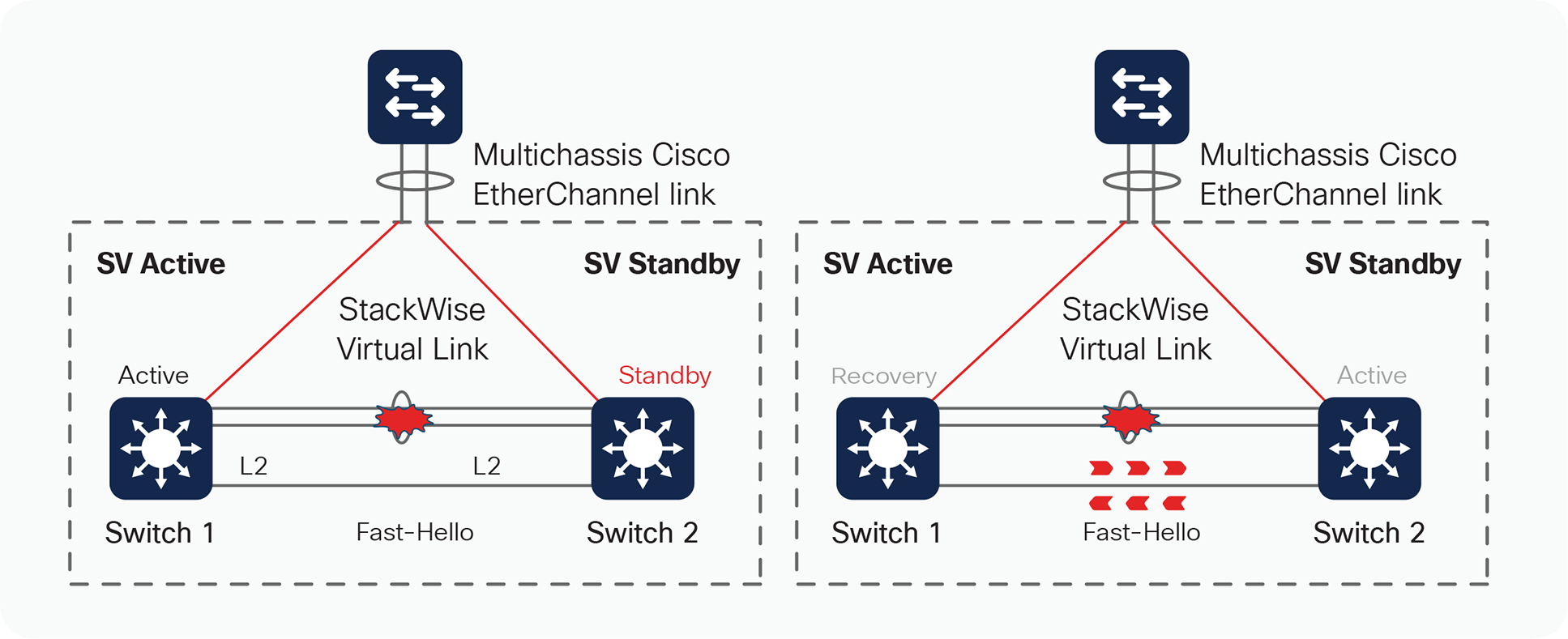
Dual-active detection using Fast Hello
In order for Fast Hello to operate, the interfaces must be enabled with this protocol. Fast Hello exchanges heartbeat messages throughout the period that the StackWise Virtual link remains up, thereby reducing the time it takes to detect the dual-active scenario.
SV-1(config)#interface fortyGigabitEthernet 1/0/12
SV-1(config-if)#stackwise-virtual dual-active-detection
WARNING: All the extraneous configurations will be removed for FortyGigabitEthernet
1/0/12 on reboot.
SV-1(config-if)#end
Up to four interfaces (directly connected) on each chassis can be configured. These interfaces must be physical interfaces, not logical ports (such as SVIs).
SV-1#show stackwise-virtual dual-active-detection
Dual-Active-Detection Configuration:
-------------------------------------
Switch Dad port Status
------ ------------ ---------
1 FortyGigabitEthernet1/0/12 up
2 FortyGigabitEthernet2/0/12 up
Enhanced PAgP
With the introduction of StackWise Virtual, an enhancement to the PAgP protocol (Enhanced PAgP or PAgP+) has been implemented to assist in dual-active detection (Figure 19).
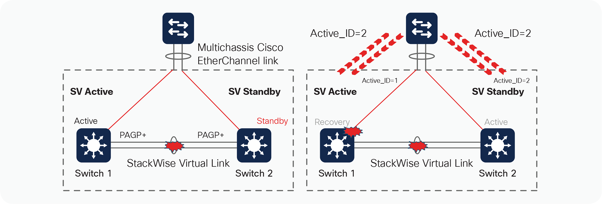
Dual-active detection mechanisms
The result of this detection is that the SV standby switch (switch 2) always transitions to become an active virtual switch, and the SV active switch (switch 1) always enters into recovery mode.
Upon the detection of the StackWise Virtual link going down on switch 2, the switch will immediately transmit a PAgP message on all port channels enabled for Enhanced PAgP dual-active detection, with a Type-Length-Value (TLV) containing its own active ID, which is 2. When the access switch receives this PAgP message on any member of the port channel, it detects that it has received a new active ID value, and considers such a change as an indication that it should consider switch 2 to be the new active switch. In turn, the access switch modifies its local active ID value to 2 and immediately sends a message to both switches on all members of the port channel with the new active ID of 2 to indicate that it now considers switch 2 to be the active switch.
From this point onward, the access switch sends TLVs containing active ID = 2 to the switches in all its regularly scheduled PAgP messages.
Use the following commands to configure Cisco StackWise Virtual to take advantage of dual-active detection using Enhanced PAgP:
SV-1#conf t
Enter configuration commands, one per line. End with CNTL/Z.
SV-1(config)#stackwise-virtual
SV-1(config-stackwise-virtual)#dual-active detection pagp trust channel-group 20
SV-1(config-stackwise-virtual)#end
You can verify the configuration with the following command:
SV-1#show stackwise-virtual dual-active-detection pagp
Note: For providing higher resiliency in dual active detection, both Fast Hello and Enhanced PAgP mechanism’s can be deployed together in the same StackWise Virtual Domain
Action upon dual-active detection
Upon detecting the dual-active condition, the original active switch enters into recovery mode and brings down all of its interfaces except the StackWise Virtual link and management interfaces. This effectively removes the device from the network.
You will see the following messages on the active virtual switch to indicate that a dual-active scenario has occurred:
*Mar 2 07:28:37.753: %NIF_MGR-6-PORT_LINK_DOWN: Switch 1 R0/0: nif_mgr: Port 0, LPN 1 on front side stack link 0 is DOWN.
*Mar 2 07:28:37.753: %NIF_MGR-6-PORT_CONN_DISCONNECTED: Switch 1 R0/0: nif_ mgr: Port 0, LPN 1 on front side stack link 0 connection has DISCONNECTED: CONN_ERR_PORT_LINK_DOWN_EVENT
*Mar 2 07:28:38.753: %LINEPROTO-5-UPDOWN: Line protocol on Interface FortyGigabitEthernet1/0/1, changed state to down Stackwise virtual: Fast Hello running and triggered dual-active recovery, setting hostname to 9500-SV(recovery-mode)
*Mar 2 07:28:39.023: %PLATFORM_PM-6-MODULE_REMOVED: SFP module with interface name Fo1/0/1 removed
*Mar 2 07:28:39.379: %NIF_MGR-6-STACK_LINK_DOWN: Switch 1 R0/0: nif_mgr: Front side stack link 0 is DOWN.
*Mar 2 07:28:39.379: %STACKMGR-1-STACK_LINK_CHANGE: Switch 1 R0/0: stack_mgr: Stack port 1 on Switch 1 is down
*Mar 2 07:28:39.393: %HMANRP-5-CHASSIS_DOWN_EVENT: Chassis 2 gone DOWN!
*Mar 2 07:28:39.473: %REDUNDANCY-3-STANDBY_LOST: Standby processor fault (PEER_NOT_PRESENT)
*Mar 2 07:28:39.473: %REDUNDANCY-3-STANDBY_LOST: Standby processor fault (PEER_DOWN)
*Mar 2 07:28:39.474: %REDUNDANCY-3-STANDBY_LOST: Standby processor fault (PEER_REDUNDANCY_STATE_CHANGE)
*Mar 2 07:28:39.754: %LINK-3-UPDOWN: Interface FortyGigabitEthernet1/0/1, changed state to down
*Mar 2 07:28:40.033: %PM-4-ERR_DISABLE: dual-active-recovery error detected on Fo1/0/3, putting Fo1/0/3 in err-disable state
*Mar 2 07:28:40.033: %PM-4-ERR_DISABLE: dual-active-recovery error detected on Fo1/0/4, putting Fo1/0/4 in err-disable state
*Mar 2 07:28:40.029: %NIF_MGR-6-DAD_RECOVERY_MODE: Switch 1 R0/0: nif_mgr: Dual Active detected: Switch going into recovery mode. since peer requested. Peer must have transitioned from Standby to Active
*Mar 2 07:28:40.033: %PM-4-ERR_DISABLE: dual-active-recovery error detected on Fo1/0/5, putting Fo1/0/5 in err-disable state
*Mar 2 07:28:40.033: %PM-4-ERR_DISABLE: dual-active-recovery error detected on Fo1/0/6, putting Fo1/0/6 in err-disable state
*Mar 2 07:28:40.033: %PM-4-ERR_DISABLE: dual-active-recovery error detected on Fo1/0/7, putting Fo1/0/7 in err-disable state
*Mar 2 07:28:40.034: %PM-4-ERR_DISABLE: dual-active-recovery error detected on Fo1/0/8, putting Fo1/0/8 in err-disable state
*Mar 2 07:28:40.034: %PM-4-ERR_DISABLE: dual-active-recovery error detected on Fo1/0/9, putting Fo1/0/9 in err-disable state
*Mar 2 07:28:41.383: %LINK-3-UPDOWN: Interface FortyGigabitEthernet2/0/1, changed state to down
*Mar 2 07:28:41.384: %LINK-3-UPDOWN: Interface FortyGigabitEthernet2/0/2, changed state to down
*Mar 2 07:28:42.032: %LINK-5-CHANGED: Interface GigabitEthernet0/0, changed state to administratively down
*Mar 2 07:28:42.383: %LINEPROTO-5-UPDOWN: Line protocol on Interface FortyGigabitEthernet2/0/1, changed state to down
*Mar 2 07:28:42.385: %LINEPROTO-5-UPDOWN: Line protocol on Interface FortyGigabitEthernet2/0/2, changed state to down
*Mar 2 07:28:43.032: %LINEPROTO-5-UPDOWN: Line protocol on Interface GigabitEthernet0/0, changed state to down
*Mar 2 07:28:46.037: %RF-5-RF_RELOAD: Peer reload. Reason: EHSA standby down
*Mar 2 07:28:46.044: %IOSXE_REDUNDANCY-6-PEER_LOST: Active detected switch 2 is no longer standby
*Mar 2 07:28:50.074: %HMANRP-6-EMP_ELECTION_INFO: EMP active switch 1 elected: EMP_ RELAY: Mgmt port status DOWN, reelecting EMP active switch
*Mar 2 07:28:50.074: %HMANRP-6-EMP_NO_ELECTION_INFO: Could not elect active EMP switch, setting emp active switch to 0: EMP_RELAY: Could not elect switch with mgmt port UP
SV-1(recovery-mode)#
The following messages on the standby virtual switch console indicate that a dual-active scenario has occurred:
%IOSXE_INFRA-6-CONSOLE_ACTIVE: R0/0 console active. Press RETURN to get started!
*Mar 2 07:28:40.054: %REDUNDANCY-3-SWITCHOVER: RP switchover (PEER_NOT_PRESENT)
*Mar 2 07:28:40.054: %REDUNDANCY-3-SWITCHOVER: RP switchover (PEER_DOWN)
*Mar 2 07:28:40.054: %REDUNDANCY-3-SWITCHOVER: RP switchover (PEER_REDUNDANCY_STATE_CHANGE)
*Mar 2 07:28:40.686: %LINK-3-UPDOWN: Interface Lsmpi19/3, changed state to up
*Mar 2 07:28:40.686: %LINK-3-UPDOWN: Interface EOBC19/1, changed state to up
*Mar 2 07:28:40.687: %LINK-3-UPDOWN: Interface LIIN19/2, changed state to up
*Mar 2 07:28:41.686: %LINEPROTO-5-UPDOWN: Line protocol on Interface Lsmpi19/3, changed state to up
*Mar 2 07:28:41.686: %LINEPROTO-5-UPDOWN: Line protocol on Interface EOBC19/1, changed state to up
*Mar 2 07:28:41.687: %LINEPROTO-5-UPDOWN: Line protocol on Interface LIIN19/2, changed state to up
*Mar 2 07:28:42.616: %LINK-3-UPDOWN: Interface FortyGigabitEthernet1/0/1, changed state to down
*Mar 2 07:28:42.616: %LINK-3-UPDOWN: Interface FortyGigabitEthernet1/0/2, changed state to down
*Mar 2 07:28:42.679: %LINK-3-UPDOWN: Interface Null0, changed state to up
*Mar 2 07:28:42.679: %LINK-3-UPDOWN: Interface Vlan2, changed state to up
*Mar 2 07:28:42.679: %LINK-3-UPDOWN: Interface Vlan31, changed state to up
*Mar 2 07:28:42.679: %LINK-3-UPDOWN: Interface Vlan32, changed state to up
*Mar 2 07:28:42.680: %LINK-3-UPDOWN: Interface FortyGigabitEthernet2/0/1, changed state to up
*Mar 2 07:28:42.680: %LINK-3-UPDOWN: Interface FortyGigabitEthernet2/0/2, changed state to up
*Mar 2 07:28:42.692: %LINK-5-CHANGED: Interface FortyGigabitEthernet1/0/15, changed state to administratively down
*Mar 2 07:28:42.692: %LINK-5-CHANGED: Interface FortyGigabitEthernet1/0/16, changed state to administratively down
*Mar 2 07:28:42.692: %LINK-5-CHANGED: Interface FortyGigabitEthernet1/0/22, changed state to administratively down
*Mar 2 07:28:42.692: %LINK-5-CHANGED: Interface FortyGigabitEthernet2/0/8, changed state to administratively down
*Mar 2 07:28:42.692: %LINK-5-CHANGED: Interface FortyGigabitEthernet2/0/15, changed state to administratively down
*Mar 2 07:28:42.692: %LINK-5-CHANGED: Interface FortyGigabitEthernet2/0/16, changed state to administratively down
*Mar 2 07:28:43.457: %NGWC_USB_CONSOLE-6-CONFIG_ENABLE: Switch 2: Console media-type changed to default
*Mar 2 07:28:43.679: %LINEPROTO-5-UPDOWN: Line protocol on Interface Null0, changed state to up
*Mar 2 07:28:43.680: %LINEPROTO-5-UPDOWN: Line protocol on Interface FortyGigabitEthernet2/0/1, changed state to up
*Mar 2 07:28:43.680: %LINEPROTO-5-UPDOWN: Line protocol on Interface FortyGigabitEthernet2/0/2, changed state to up
*Mar 2 07:28:52.688: %LINK-3-UPDOWN: Interface GigabitEthernet0/0, changed state to up
*Mar 2 07:28:53.689: %LINEPROTO-5-UPDOWN: Line protocol on Interface GigabitEthernet0/0, changed state to up
Recovery from a dual-active scenario
If a StackWise Virtual link flap occurs, the system currently does not recover automatically. Upon a link-up event from any of the StackWise Virtual links, the previous active switch that is now in recovery mode has to be manually reloaded, allowing it to initialize as the hot-standby switch. From 16.11.1 release, the system does not require a manual reload and will recover automatically.
When the StackWise Virtual link is restored, the following messages are displayed on the console when the switch in recovery mode (the previous active virtual switch) is manually reloaded:
SV-1#
*Mar 2 07:48:07.166: %LINK-3-UPDOWN: Interface FortyGigabitEthernet2/0/1, changed state to up
*Mar 2 07:48:07.166: %NIF_MGR-6-PORT_LINK_UP: Switch 2 R0/0: nif_mgr: Port 0, LPN 1 on front side stack link 0 is UP.
*Mar 2 07:48:07.166: %NIF_MGR-6-PORT_CONN_PENDING: Switch 2 R0/0: nif_mgr: Port 0, LPN 1 on front side stack link 0 connection is PENDING.
*Mar 2 07:48:08.166: %LINEPROTO-5-UPDOWN: Liee3ne protocol on Interface FortyGigabitEthernet2/0/1, changed state to up
*Mar 2 07:48:08.194: %STACKMGR-1-DUAL_ACTIVE_CFG_MSG: Switch 2 R0/0: stack_mgr: Dual Active Detection link is available now
*Mar 2 07:48:08.195: %LINK-3-UPDOWN: Interface FortyGigabitEthernet2/0/2, changed state to up
*Mar 2 07:48:09.195: %LINEPROTO-5-UPDOWN: Line protocol on Interface FortyGigabitEthernet2/0/2, changed state to up
*Mar 2 07:48:10.124: %NIF_MGR-6-PORT_CONNECTION_STATUS_CHANGE: Switch 2 R0/0: nif_mgr: PORT lpn:1 changed state from Pending to Timeout.
*Mar 2 07:48:10.124: %NIF_MGR-6-PORT_CONN_TIMEOUT: Switch 2 R0/0: nif_mgr: Port 0, LPN 1 on front side stack link 0 connection has TIMEOUT: CONN_ERR_CONN_TIMEOUT_ERR
*Mar 2 07:48:30.656: %NIF_MGR-6-PORT_LINK_DOWN: Switch 2 R0/0: nif_mgr: Port 0, LPN 1 on front side stack link 0 is DOWN.
*Mar 2 07:48:30.656: %NIF_MGR-6-PORT_CONN_DISCONNECTED: Switch 2 R0/0: nif_ mgr: Port 0, LPN 1 on front side stack link 0 connection has DISCONNECTED: CONN_ERR_PORT_LINK_DOWN_EVENT
*Mar 2 07:48:33.380: %NIF_MGR-6-PORT_LINK_UP: Switch 2 R0/0: nif_mgr: Port 0, LPN 1 on front side stack link 0 is UP.
*Mar 2 07:48:33.380: %NIF_MGR-6-PORT_CONN_PENDING: Switch 2 R0/0: nif_mgr: Port 0, LPN 1 on front side stack link 0 connection is PENDING.
*Mar 2 07:48:34.125: %NIF_MGR-6-PORT_CONNECTION_STATUS_CHANGE: Switch 2 R0/0: nif_mgr: PORT lpn:1 changed state from Pending to Timeout.
*Mar 2 07:48:34.125: %NIF_MGR-6-PORT_CONN_TIMEOUT: Switch 2 R0/0: nif_mgr: Port 0, LPN 1 on front side stack link 0 connection has TIMEOUT: CONN_ERR_CONN_TIMEOUT_ERR
*Mar 2 07:48:40.126: %NIF_MGR-6-PORT_CONNECTION_STATUS_CHANGE: Switch 2 R0/0: nif_mgr: PORT lpn:1 changed state from Timeout to Pending.
*Mar 2 07:48:40.126: %NIF_MGR-6-PORT_CONN_PENDING: Switch 2 R0/0: nif_mgr: Port 0, LPN 1 on front side stack link 0 connection is PENDING.
*Mar 2 07:48:43.126: %NIF_MGR-6-PORT_CONNECTION_STATUS_CHANGE: Switch 2 R0/0: nif_mgr: PORT lpn:1 changed state from Pending to Ready.
*Mar 2 07:48:43.126: %NIF_MGR-6-PORT_CONN_READY: Switch 2 R0/0: nif_mgr: Port 0, LPN 1 on front side stack link 0 connection is READY.
*Mar 2 07:48:43.126: %NIF_MGR-6-STACK_LINK_UP: Switch 2 R0/0: nif_mgr: Front side stack link 0 is UP.
*Mar 2 07:48:43.128: %STACKMGR-1-STACK_LINK_CHANGE: Switch 2 R0/0: stack_mgr: Stack port 1 on Switch 2 is up
*Mar 2 07:48:43.851: %STACKMGR-6-SWITCH_ADDED: Switch 2 R0/0: stack_mgr: Switch 1 has been added to the stack.
*Mar 2 07:48:50.954: %NIF_MGR-6-PORT_LINK_UP: Switch 1 R0/0: nif_mgr: Port 0, LPN 1 on front side stack link 0 is UP.
*Mar 2 07:48:50.954: %NIF_MGR-6-PORT_CONN_PENDING: Switch 1 R0/0: nif_mgr: Port 0, LPN 1 on front side stack link 0 connection is PENDING.
*Mar 2 07:48:50.954: %NIF_MGR-6-PORT_CONNECTION_STATUS_CHANGE: Switch 1 R0/0: nif_mgr: PORT lpn:1 changed state from Pending to Ready.
*Mar 2 07:48:50.954: %NIF_MGR-6-PORT_CONN_READY: Switch 1 R0/0: nif_mgr: Port 0, LPN 1 on front side stack link 0 connection is READY.
*Mar 2 07:48:50.954: %NIF_MGR-6-STACK_LINK_UP: Switch 1 R0/0: nif_mgr: Front side stack link 0 is UP.
*Mar 2 07:48:50.955: %STACKMGR-1-STACK_LINK_CHANGE: Switch 1 R0/0: stack_mgr: Stack port 2 on Switch 1 is nocable
*Mar 2 07:48:50.955: %STACKMGR-1-STACK_LINK_CHANGE: Switch 1 R0/0: stack_mgr: Stack port 1 on Switch 1 is down
*Mar 2 07:48:50.955: %STACKMGR-1-DUAL_ACTIVE_CFG_MSG: Switch 1 R0/0: stack_mgr: Dual Active Detection link is available now
*Mar 2 07:48:50.955: %STACKMGR-1-STACK_LINK_CHANGE: Switch 1 R0/0: stack_mgr: Stack port 1 on Switch 1 is up
*Mar 2 07:48:50.955: %STACKMGR-6-SWITCH_ADDED: Switch 1 R0/0: stack_mgr: Switch 1 has been added to the stack.
*Mar 2 07:48:51.750: %HMANRP-6-HMAN_IOS_CHANNEL_INFO: HMAN-IOS channel event for switch 1: EMP_RELAY: Channel UP!
*Mar 2 07:48:59.114: %PLATFORM_PM-6-MODULE_INSERTED: SFP module inserted with interface name Fo1/0/1
*Mar 2 07:48:59.115: %PLATFORM_PM-6-MODULE_INSERTED: SFP module inserted with interface name Fo1/0/2
*Mar 2 07:49:01.109: %LINK-3-UPDOWN: Interface FortyGigabitEthernet1/0/1, changed state to up
*Mar 2 07:49:01.110: %LINK-3-UPDOWN: Interface FortyGigabitEthernet1/0/2, changed state to up
After the chassis reloads, it reinitializes and the switch enters into SV standby mode.
Finally, traffic convergence associated with a StackWise Virtual link failure scenario involves the dual-active detection mechanisms, the recovery mode operations, and the restoration period, which involves a reload of the previously active StackWise Virtual switch. In each of the three previous stages, there is a possibility for some traffic disruption. Typically, the disruption will be similar to the NSF/SSO switchover scenarios described previously, but other factors from the overall network design can have an impact as well. These include the types of connections to the StackWise Virtual link, either Layer 2 or Layer 3 multichassis EtherChannels or equal-cost paths.
Quality of Service (QoS) handling on the Cisco Catalyst 9000 switching family is typically handled by port-based QoS features for ensuring differentiated servicing of traffic throughout the system.
In a StackWise Virtual environment, proper QoS handling becomes even more important for the following reasons:
● Control traffic between the two StackWise Virtual switches (active switch and standby switch) should be prioritized and should not be dropped.
● The existence of the StackWise Virtual link and multichassis EtherChannel links represents potential points of congestion that must be properly accounted for.
Additionally, the nature of dual-homing logical connections across different switches and forwarding engines represents a change in the way features such as policing and marking work. These features need to be properly accounted for.
StackWise Virtual link as a congestion point
From a system-level perspective, the StackWise Virtual link can be viewed as a backplane connection that bonds the two virtual switch chassis together into a single logical entity. While provisions have been made for EtherChannel and Equal Cost Multipath (ECMP) hashing mechanisms (refer to the section “EtherChannel Concepts”), under certain. circumstances (in the case of single-homed connections, whether by design or if failures occur), it may be possible to oversubscribe the links that form the StackWise Virtual link.
The StackWise Virtual link should always consist of at least two ports of 40 or 10 Gigabit Ethernet connections. However, because of hash inefficiencies, it may be possible to oversubscribe a single StackWise Virtual link member port. Therefore, correct prioritization needs to occur on the StackWise Virtual link.
Prioritization is accomplished on the StackWise Virtual via DSCP markers. The DSCP are hardcoded to the SVL port queues. All DSCP values are preserved and trusted over the SVL link. All SVL control traffic does not use DSCP markers but a specific VLAN 4094 where all SVL control packets are sent. (Figure 20).
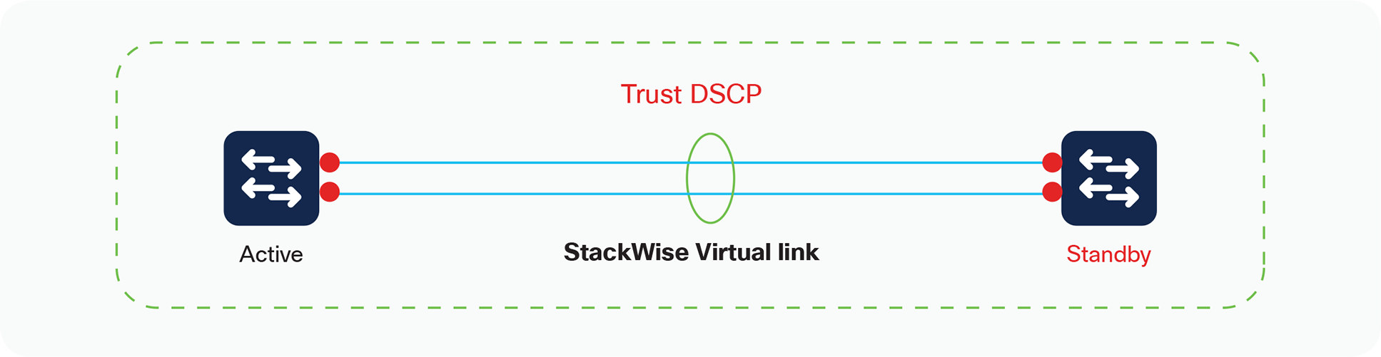
StackWise Virtual QoS
The following output shows the interfaces configured as a StackWise Virtual link, and it has the QoS configuration of trust DSCP programmed by default. Note that removing or modifying this trust command is not permitted:
SV-1# show stackwise-virtual link
Stackwise Virtual Link(SVL) Information:
----------------------------------------
Flags:
------
Link Status
-----------
U-Up D-Down
Protocol Status
---------------
S-Suspended P-Pending E-Error T-Timeout R-Ready
-----------------------------------------------
Switch SVL Ports Link-Status Protocol-Status
------ --- ----- ----------- ---------------
1 1 FortyGigabitEthernet1/0/1 U R
2 1 FortyGigabitEthernet2/0/1 U R
SV-1#show platform software fed switch 1 qos qsb interface fortyGigabitEthernet 1/0/1
QoS subblock information:
Name:FortyGigabitEthernet1/0/1 iif_id:0x00000000000008 iif_type:ETHER(146)
qsb ptr:0x7fdc4c4c2358
Port type = Wired port
asic_num:7 is_uplink:false init_done:1
FRU events: Active-0, Inactive-0
def_qos_label:0 def_le_priority:13
trust_enabled:true trust_type:TRUST_DSCP ifm_trust_type:0
LE priority:11 LE tablemap handle(in, out): (0,0)
Stats (plc,q) export counters (in/out): 0/0
Policy Info:
Ingress Policy:nil
Egress Policy:nil
TCG(in,out):((nil), (nil))
Policer Info: Aggregate
Ingress policer block: Not allocated
Egress policer block: Not allocated
Instance Handle: Not allocated
Policer Info: Microflow
Ingress policer block: Not allocated
Egress policer block: Not allocated
Instance Handle: Not allocated
Queueing Info:
def_queuing = 1, shape_rate:0 interface_rate_kbps:40000000
Port shaper:false
lbl_to_qmap_index:0
QoS settings cannot be changed on the StackWise Virtual link interfaces. Additionally, custom policy maps used for classification or policing or remarking are forbidden on the StackWise Virtual link and its respective members.
Control traffic over the StackWise Virtual link
Multiple types of control traffic must be parsed between the two virtual switches, including StackWise Discovery Protocol and other in-band messages. These special control frames are tagged with a label internal to the system, indicating that they require specialized treatment, and are automatically assigned to the priority queue of the interface for expedited delivery. As a result, no extra configuration is required.
Figure 21 shows the queue structures for 16.6 and above releases. The priority queue is always serviced first for vlan 4094, prior to any other Weighted Round Robin (WRR) queues.
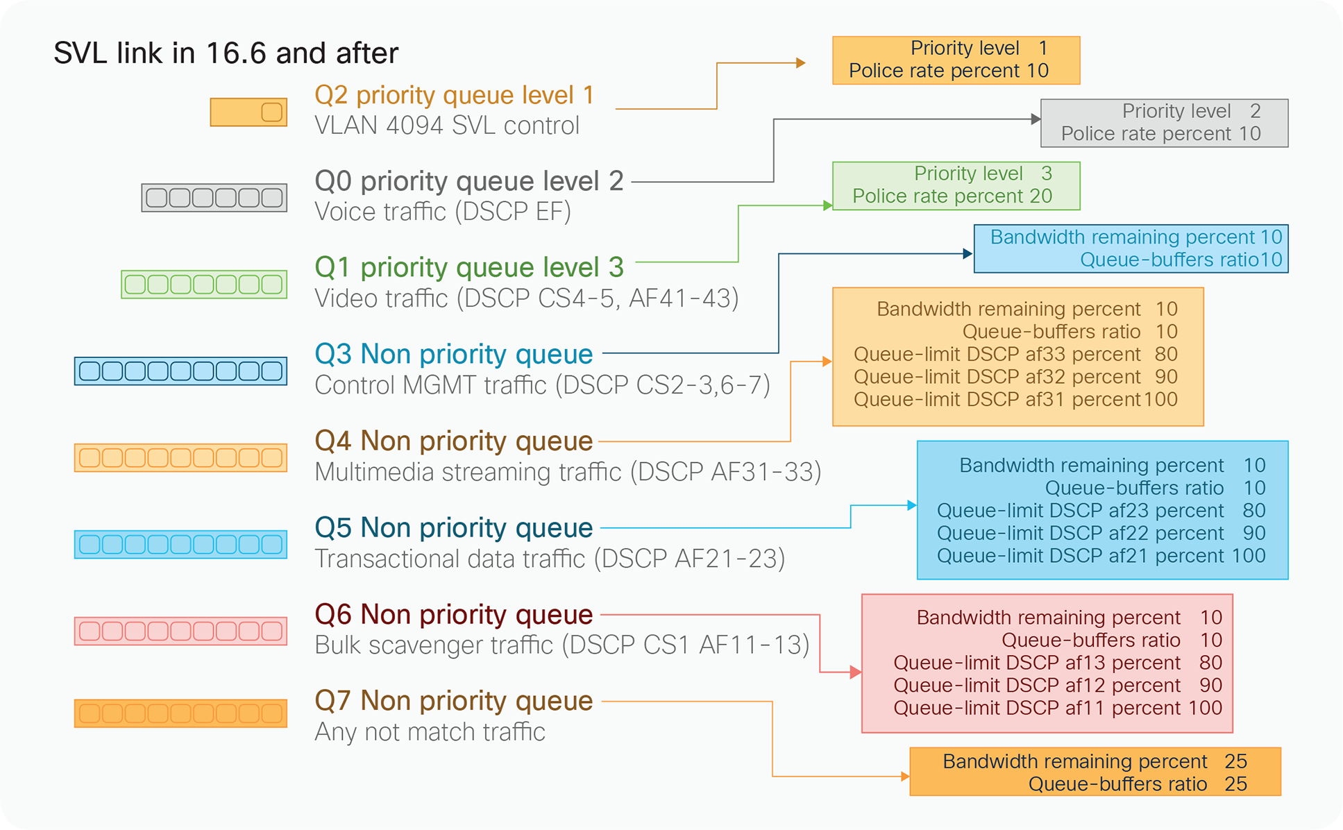
SSVL Queue structure
StackWise Virtual In-Service software upgrades
StackWise Virtual Supports In-Service Software Upgrades. ISSU helps network administrators avoid a network outage `when performing IOS XE software upgrade on StackWise Virtual pair. ISSU supports upgrades and rollbacks.
Please refer to StackWise Virtual ISSU configuration Guide for more details.
Conclusion
Cisco Catalyst 9000 family switches in a Cisco StackWise Virtual solution simplify operational efficiency with a single control and management plane, scale system bandwidth with a distributed forwarding plane, and assist in building resilient networks using the recommended network design.