Cisco UCS VIC 1400 Series Best Practices in Ethernet Fabric White Paper
Available Languages
Bias-Free Language
The documentation set for this product strives to use bias-free language. For the purposes of this documentation set, bias-free is defined as language that does not imply discrimination based on age, disability, gender, racial identity, ethnic identity, sexual orientation, socioeconomic status, and intersectionality. Exceptions may be present in the documentation due to language that is hardcoded in the user interfaces of the product software, language used based on RFP documentation, or language that is used by a referenced third-party product. Learn more about how Cisco is using Inclusive Language.
The Cisco Unified Computing System (Cisco UCS) is a next-generation data center platform that unites computing, networking, storage access, and virtualization resources into a cohesive system designed to reduce Total Cost of Ownership (TCO) and increase business agility.
The fourth-generation Cisco UCS Virtual Interface Card 1400 series supports 10/25/40/100-Gigabit Ethernet and Fiber Channel over Ethernet speeds, Cisco’s next-generation converged network adapter technology, and a comprehensive set of features for UCS B-series blade servers, C-series rack servers, and S-series storage servers.
The Cisco UCS Virtual Interface Card (VIC) incorporates the Converged Network Adapter (CNA) technology and offers a comprehensive feature set, providing investment protection across multiple generations of UCS blade and rack server.
The Cisco VIC 1400 series is the fourth generation of VICs available in multiple form factors (1440, 1480, 1455, 1457, 1495, and 1497) and speed (10/25/40/100Gbps). For a comprehensive look into the supported features, please refer to the Cisco UCS VIC 1400 datasheet.
The audience for this document consists of system architects, system engineers, and any other technical staff who are responsible for planning and maintaining the UCS infrastructure. Although every effort has been made to make this document appeal to the widest possible audience, the document assumes that readers have an understanding of Cisco UCS hardware, terminology, and configurations.
This document tries to address some of the frequently asked questions about the Cisco UCS VIC 1400 series and the recommended practices from an Ethernet fabric perspective. The following topics are addressed in this document: bandwidth with VIC 1400 on blade servers, best-practices for adapter policies, overlay offloads, FEC settings, and various VIC connectivity considerations for rack servers.
Cisco UCS blade-servers (for example, Cisco UCS B200 M5 and B480 M5 blade servers) have converged network adapters in MLOM and mezzanine card form-factor. For the fourth-Generation VIC, this would be the VIC 1440 (MLOM) and VIC 1480 (mezzanine). The VIC 1440 also can work with an optional Port-Expander (PE), which enables extra bandwidth on the VIC-1440 adapter.
The half-width (B200 M5) or full-width (B480 M5) blade server on a UCS 5108 chassis will see different throughputs and NIC/HBA (vNIC/vHBA in UCS) speeds per VIC adapter depending on a combination of:
● VIC (1440, 1440+PE, or 1480) installed on a blade server
● IOMs (2204, 2208, 2304v1/v2, or 2408) on the chassis
● Fabric Interconnects (FIs) (6200 series, 6300 series, or 6400 series)
On a UCS 5108 chassis, each IOM has multiple 10G-KR backplane connections towards the VIC card on the server. Each IOM 2208, 2304, and 2408 on a UCS 5108 chassis has four 10G-KR connections toward a B200 M5 blade server and eight 10G-KR connections toward a B480 M5 blade server.
Note: The IOM 2304 referenced in this document implies an IOM 2304v1 or an IOM 2304v2.
The following diagram below shows the connectivity on a UCS 5108 chassis with IOM 2408 connected to FI 6454. The red lines are the 25Gbps physical connections from IOM to FI while the blue-lines show the 10G-KR backplane connections from the IOM toward the VIC on a B200 M5 server.
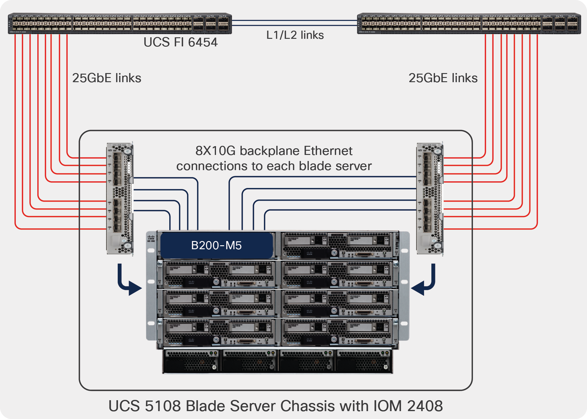
Cisco UCS 5108 chassis with FI 6454 and IOM 2408
Throughput for the B200 M5 / B480 M5 server depends on which VICs are installed on the server and how many backplane connections get enabled due to this. Broadly speaking, the following examples explain the throughput to be expected from a blade-server:
● B200 M5 with only VIC 1440 will have two 10G-KR connections enabled toward IOM 2208/2304/2408.
● B200 M5 with VIC 1440 + 1480 will have four 10G-KR connections enabled toward IOM 2208/2304/2408.
● B200 M5 with VIC 1440 + PE will have four 10G-KR connections toward IOM 2304/2408.
The table below shows the throughput per B200 M5 or B480 M5 with various 1440 and 1480 combinations. The throughput from the server is calculated across both the fabric interconnects in the UCS domain.
Please note that 1440/1480 is supported by M5 servers and future blade-servers. Though Table 1 is for M5 servers, the throughput information will be the same in future UCS 5108 chassis blade server generations.
Table 1. VIC 1440/1480 throughput per blade server
| Adapter combinations on a blade server |
FI 6400 + IOM 2408 |
FI 6300 + IOM 2304 |
FI 6200/ 6300/ 6400 + IOM 2208 |
FI 6200/ 6300/ 6400 + IOM 2204 |
FI 6324 |
|||||
|
|
B200 M5 |
B480 M5 |
B200 M5 |
B480 M5 |
B200 M5 |
B480 M5 |
B200 M5 |
B480 M5 |
B200 M5 |
B480 M5 |
| 1440 |
40G |
40G |
40G |
40G |
40G |
40G |
20G |
20G |
20G |
20G |
| 1440 + PE |
80G |
80G |
80G |
80G |
N/A |
N/A |
N/A |
N/A |
N/A |
N/A |
| 1440 + 1480 |
80G |
120G |
80G |
120G |
80G |
80G |
40G |
40G |
40G |
40G |
| 1440 + PE + 1480 |
N/A |
160G |
N/A |
160G |
N/A |
N/A |
N/A |
N/A |
N/A |
N/A |
| 1440 + 1480 + 1480 |
N/A |
160G |
N/A |
160G |
N/A |
160G |
N/A |
60G |
N/A |
N/A |
On a B200 M5 / B480 M5, VIC 1440 and 1480 adapters can have 10G, 20G, or 40G vNICs. And the vNIC speed seen on the server depends on the various VIC combinations installed on the blade server, as in the following:
● With 1440 on a B200 M5 or B480 M5, the server will see 20Gbps (2x10) throughput with all IOMs except 2204 and fabric interconnect 6324.
● 1440 with port-expander on B200 M5 or B480 M5 will enable 40G KR4 toward IOM 2304 and IOM 2408. This is supported by IOM 2304 in Cisco UCS Manager (UCSM) releases 4.0 onwards; meanwhile, support for 40G KR4 with IOM 2408 is available from Cisco UCSM release 4.1(2).
● 1480 in B200 M5 will see 20Gbps (2x10) throughput.
● 1480 in slot 3 of B480 M5 can have 40G throughput. This is supported by IOM 2304 in Cisco UCSM releases 4.0 onwards. With IOM 2408, 20Gbps (2x10G) was supported initially and from Cisco UCSM release 4.1(2), 40G is supported.
The table below shows the vNIC aggregate speed and the expected maximum single-flow bandwidth per vNIC on an adapter.
In the table, 2x10G means vNIC will have an aggregate speed of 20G and a maximum single-flow of 10Gbps. A 40G vNIC on a 1400 VIC with IOM 2304 can have a single-flow max of 40Gbps; while with IOM 2408, it would be a single-flow max of 25Gbps and aggregate of 40Gbps across multiple flows. Details on the 40G capability of VIC 1440/1480 with IOM 2408 and IOM 2304 are explained in the next section.
For example in the below table, the highlighted combination of a blade server has both VIC 1440 and 1480 installed. With both adapters installed on the B200 M5, each of the VIC 1440 and 1480 adapters will see vNICs with a speed of 20G (2x10G). While on the B480 M5, vNICs on VIC 1440 will be 20Gbps, and vNICs on VIC 1480 installed in slot 3 will be 40Gbps.
Table 2. vNIC speed per VIC 1440/1480 adapter
| Adapters on a blade server |
FI 6400 + IOM 2408 |
FI 6300 + IOM 2304v1/v2 |
FI 6200/ 6300/ 6400 + IOM 2208 |
FI 6200/ 6300/ 6400 + IOM 2204 |
FI 6324 |
|||||
| B200 M5 |
B480 M5 |
B200 M5 |
B480 M5 |
B200 M5 |
B480 M5 |
B200 M5 |
B480 M5 |
B200 M5 |
B480 M5 |
|
| 1440 |
2x10G |
2x10G |
2x10G |
2x10G |
2x10G |
2x10G |
10G |
10G |
10G |
10G |
| 1440 + PE |
40G** |
40G** |
40G |
40G |
N/A |
N/A |
N/A |
N/A |
N/A |
N/A |
| 1440 + 1480 |
2x10G |
2x10G |
2x10G |
2x10G |
2x10G |
2x10G |
10G |
10G |
10G |
10G |
| 2x10G |
40G** |
40G |
40G |
2x10G |
2x10G |
10G |
10G |
10G |
10G |
|
| 1440 + PE + 1480 |
N/A |
40G** |
N/A |
40G |
N/A |
N/A |
N/A |
N/A |
N/A |
N/A |
| 40G** |
40G |
|||||||||
| 1440 + 1480 + 1480 |
N/A |
2x10G |
N/A |
2x10G |
N/A |
2x10G |
N/A |
10G |
N/A |
N/A |
| 2x10G |
2x10G |
2x10G |
|
10G |
||||||
| 40G** |
40G |
2x10G |
10G |
|||||||
VIC 1440 + port expander
Port-expander support with VIC 1440 on M5 blade servers are available with the following FI and IOM combinations:
● FI 6300 series + IOM 2304
● FI 6400 series + IOM 2408 from Cisco UCSM Release 4.1(2)
FI 6300 series + IOM 2304
On the UCS 5108 chassis, the B200 M5 or B480 M5 server with 1440 + port-expander will enable 40G KR4 interface toward the IOM. The servers, in this case, will see vNIC bandwidth of 40Gbps and each vNIC will support a maximum single flow of 40Gbps. Below diagram depicts the back-plane connections that gets enabled on a UCS 5108 chassis with VIC1440 and port-expander in a B200-M5 chassis.
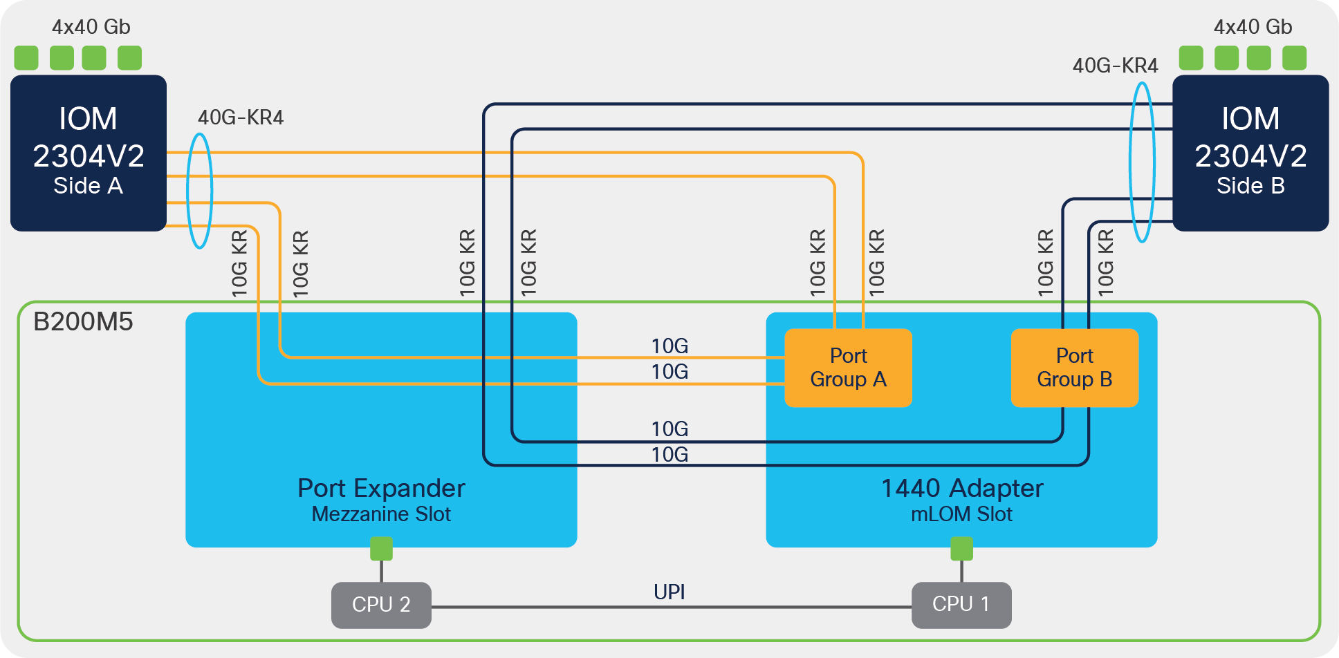
B200 M5 with VIC 1440 + port expander and IOM 2304
With port-expander, vNIC on 1440 will see a speed of 40G due to the 40G-KR4 interface that gets enabled towards IOM-2304 as shown above.
Without a port expander, vNIC on 1440 will only see a speed of 20G or 2x10G, and the vNIC will have an aggregate bandwidth of 20G with a maximum single-flow bandwidth of 10Gbps.
Similarly, vNIC on 1480 with 6300 + IOM 2304 have a 2x10G (20G) or native 40G speed, depending on which server they are placed.
● On B200 M5 with 1440 + 1480 adapters, vNICs on both 1440 and 1480 will see a speed of 2x10G (20G).
● While on B480 M5 when 1480 is installed in slot 3, vNIC on the 1480 will see a native 40G speed, after 40G-KR4 interface towards the IOM-2304 gets enabled.
FI 6400 series + IOM 2408
On a 5108 chassis with IOM 2408 and a B200 M5 or B480-M5 server, 40G KR4 for VIC 1440 and 1480 are enabled from Cisco UCSM Release 4.1(2a).
Please note that these are 40G-KR4 interfaces from the VIC 1440/1480 towards the IOM 2408 and not 4x10Gbps hardware port-channel.
The 40G KR4 gets enabled for 1440 + PE on B200 M5 and B480 M5. And on the VIC 1480, the 40G KR4 is enabled when it’s installed on the slot 3 of a B480 M5.
Below pictures depict various possible combinations of the back-plane traces that gets enabled on UCS 5108 chassis with 1440 and port-expander in a Cisco UCS B200-M5 or B480-M5 blade-server.
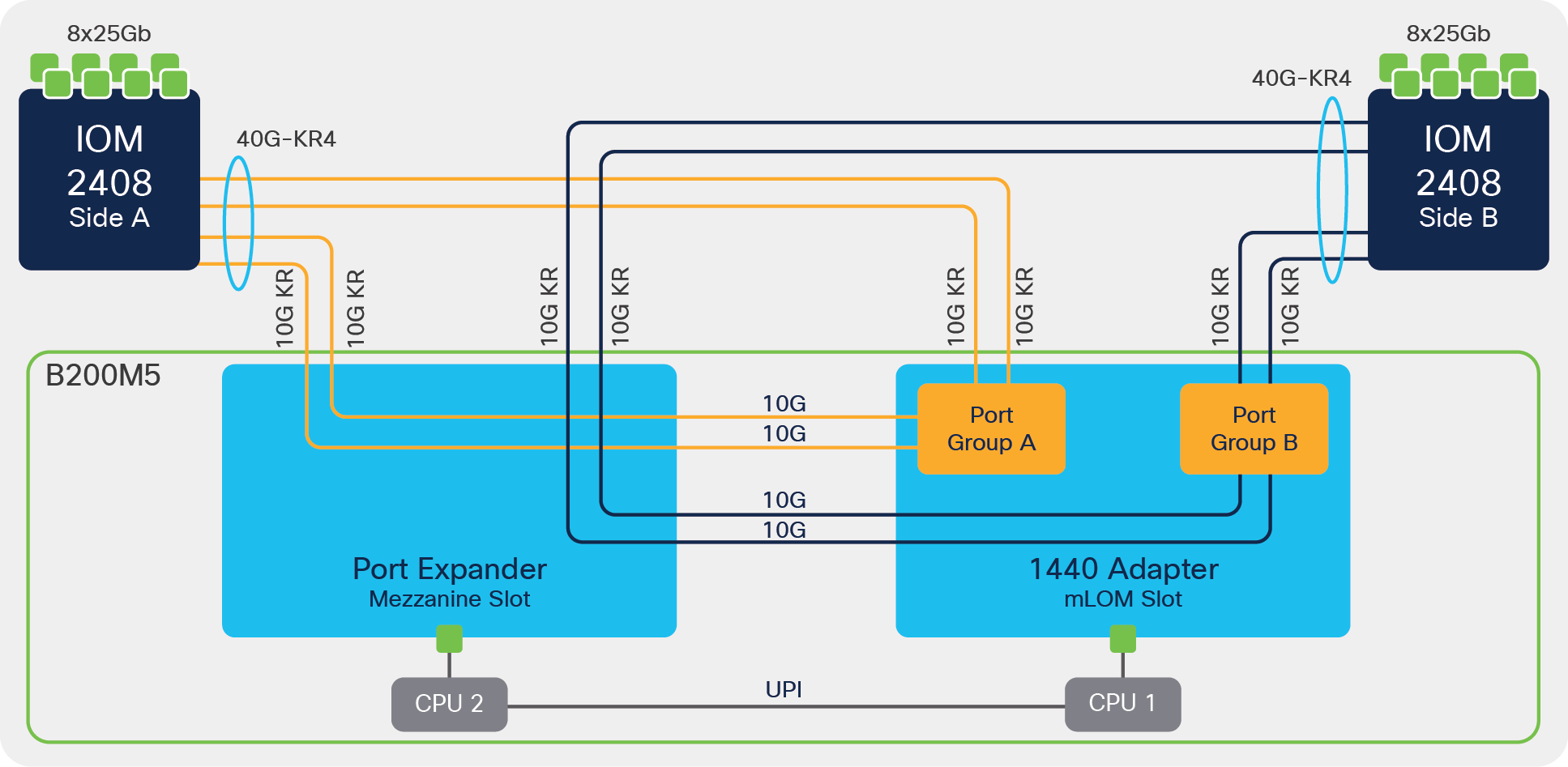
B200 M5 with VIC 1440 + port expander and IOM
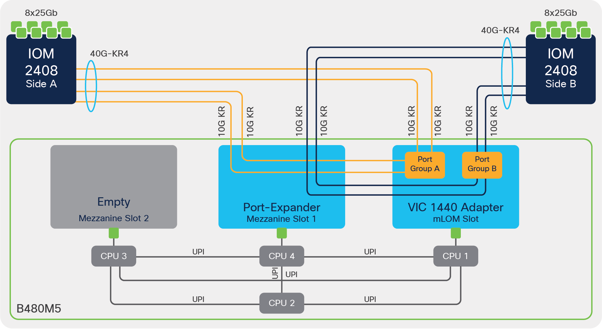
B480 M5 with VIC 1440 + Port Expander and IOM
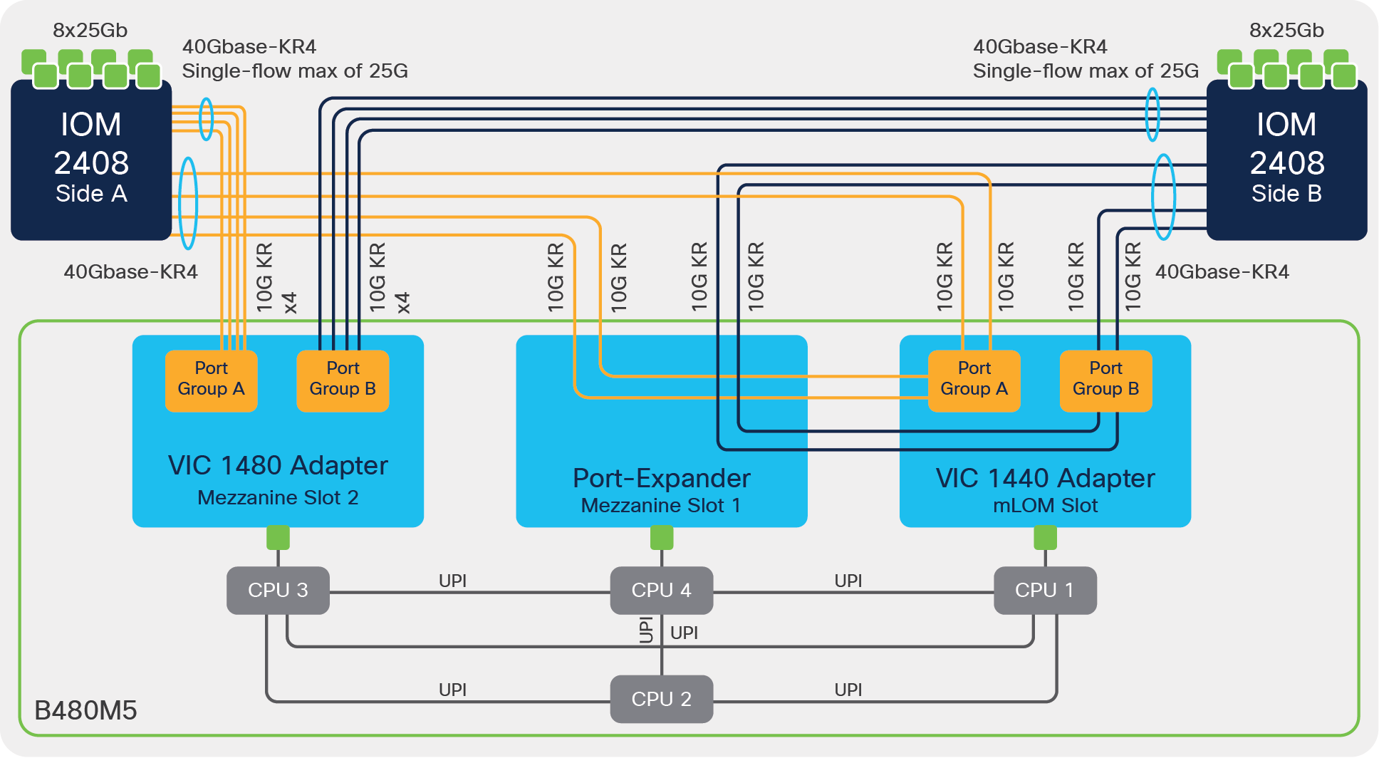
B480 M5 with VIC 1440 + Port Expander, VIC 1480 and IOM
Even though 40G-KR4 gets enabled between VIC 1440/1480 to IOM-2404, the connection to FI 6400 series from IOM-2408 is over 25Gbps Ethernet links. And on the IOM a single flow from the server/vNIC gets hashed to one of the IOM-2408 25Gbps ports; hence, each vNIC can achieve a maximum single-flow bandwidth of 25Gbps, even though the server-to-IOM connectivity is 40G KR4 or native 40Gbps.
To avoid initial transient packet-drop for a flow on the IOM 2408 due to this bandwidth mismatch of 40Gbps from the server toward IOM 2408 and the 25Gbps Ethernet connection between IOM 2408 and FI 6400, the vNICs can be rate-limited to 25Gbps. The vNIC rate-limiting can be achieved through a QoS policy applied to the vNIC.
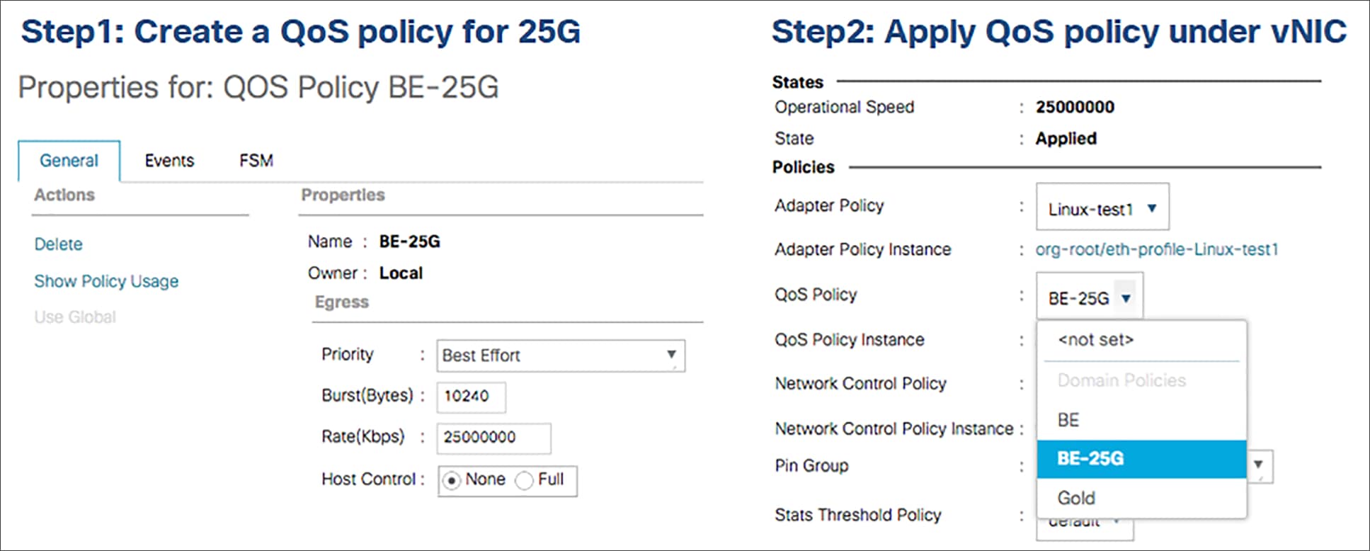
vNIC rate-limiting configuration
Like VIC 1440, vNIC on 1480 with FI 6400 and IOM 2408 can have 2x10G (20G) or native 40G speed, depending on the server its installed.
● On B200 M5 with 1440 + 1480 adapters, vNICs on both 1440 and 1480 will see 2x10G (20G) speed.
● While on B480 M5 when 1480 is installed in slot 3, vNICs on 1480 will see native 40G speed.
The 25Gbps rate-limiting recommendation is applicable for vNICs on the VIC 1480 also when a 40G-KR4 interface with IOM 2408 is enabled from UCSM release 4.1(2).
Before UCSM release 4.1(2), there was no support for the port expander with 1440 and IOM 2408. And both VIC 1440 and 1480 supported only 2x10G (20G) per vNIC on each of these adapters with IOM 2408.
Performance tuning of a Cisco UCS M5 server involves: BIOS policy tuning, VIC adapter tuning, and OS tuning.
BIOS policy tuning for UCS servers is detailed in the following whitepaper “Performance Tuning Guide for Cisco UCS M5 Servers”[1].
OS tuning is not something specific to UCS servers and one should follow the OS best practices. The focus of this section is to provide VIC tuning recommendations for achieving maximum performance out of the Cisco UCS VIC 1400 adapters.
The focus would be primarily on the following VIC 1400 features and recommendations to maximize performance:
● VIC Adapter policy with RSS for Linux, Windows, and ESXi
● VMQ or NetQueue support for ESXi
● VMMQ support for Windows
● MTU setting
● Overlay offload
VIC 1400 series adapters supports Receive Side Scaling (RSS), Virtual Machine Queue (VMQ), or Virtual Machine Multiple Queue (VMMQ). In the next few sections will cover nuances of each of these features that are specific to VIC 1400 and customers could deploy any of these solutions based on their server’s requirements.
Receive side scaling, or RSS, is a VIC hardware feature that allows for distributing traffic across multiple RX queues on the adapter and have them processed across multiple CPU cores. Having traffic spread across multiple RX queues and processed by different CPU cores helps in driving higher throughput for the server and in achieving better CPU utilization for the CPU cores in the server.
Having an adapter policy with RSS enables this VIC hardware solution, in which packets are load balanced across multiple RX queues based on the packets Layer 2, Layer 3, and Layer 4 headers. It’s an optimal, as well as a simpler, solution for improving performance in bare-metal (Windows, Linux) and hypervisor (ESXi, KVM) installations.
Along with higher number of RX queues and RSS, another important consideration to improve performance is to increase the ring size per queue on the VIC adapter. Increasing the ring size allows for more packet buffering per queue, thus preventing dropped packets and retransmissions.
All of these configurations – of TX/RX queues, ring size, and RSS – are enabled through the adapter policy attached to a vNIC for the Cisco UCSM–managed server or from the vNIC properties in the Cisco Integrated Management Controller (IMC) for a standalone rack server.
In Cisco UCSM, there are predefined adapter policies available based on the application and OS. The default Ethernet adapter-policies on UCSM for the various operating systems with VIC 1400 are as follows:
● Eth Adapter Policy “Linux” for Linux
● Eth Adapter Policy “Linux-NVMe-RoCE for ROCEv2 with Linux
● Eth Adapter Policy “VMWare” for ESXi
● Eth Adapter Policy “Win-HPN” for Windows
● Eth Adapter Policy “Win-HPN-SMBd” for ROCEv2 with Windows
The default adapter policies across operating systems and workloads are good enough for the majority of UCS server deployments. But at the same time, depending on applications and server needs, one will have to modify or define new adapter policy. Table 3 presents adapter policy recommendations in terms of TX/RX queues and RSS which addresses majority of higher throughput, and performance requirements seen by many customers.
These adapter-policy recommendations are independent of the Cisco Validated Design (CVD) recommendations for the various UCS solutions. The CVD recommendations should be followed when deploying the corresponding CVD solutions. Also please note that, depending on the application, multiple TX/RX queues could be defined differently from the values given in the table, and these adapter-policy recommendations are for the VIC 1400 series.
Table 3. Recommended adapter policy for performance with RSS
| Parameter |
ESXi |
Linux |
Windows |
| TX queue |
1 |
1 |
1 |
| TX ring size |
4096 |
4096 |
4096 |
| RX queue |
8 |
8 |
8 |
| RX ring size |
4096 |
4096 |
4096 |
| CQ |
9 |
9 |
9 |
| Interrupt |
11 |
11 |
512 |
| RSS |
Enabled |
Enabled |
Enabled |
CQ, or completion queue, is “RX + TX” for all operating systems; included below are some of the adapter-policy recommendations for ESXi, Linux, and Windows OS with multiple TX/RX queues and RSS.
ESXi
Cisco UCS VIC 1400 adapter-policy considerations for the VIC RSS feature with ESXi are the following:
● The ESXi VIC driver supports only 1 TX queue while it supports multiple RX queues with RSS.
● Maximum supported number of RX queues is 16 for all ESXi versions except ESXi 6.0.
● ESXi 6.0 supports 8 RX queues.
● Having a ring-size of 4096 for TX/RX queues allows for more packet buffering and will help in overall throughput and having lower retransmissions.
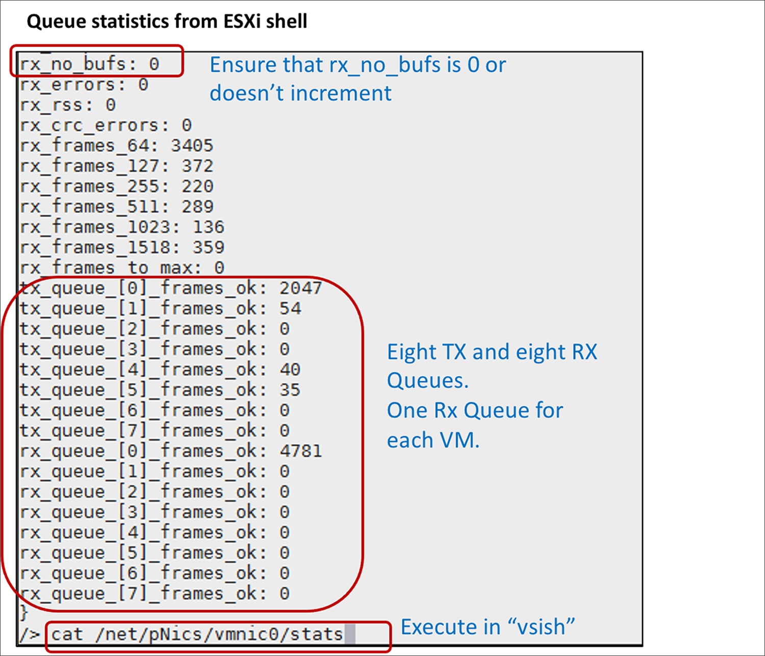
● If the pNIC/VMNIC statistics in the ESXi host show “rx_no_bufs” as incrementing, this indicates slower processing of packets by the ESXi host; the recommendation to fix this is to increase the RX queues or the RX ring-size or a combination of both on the vNIC adapter policy.
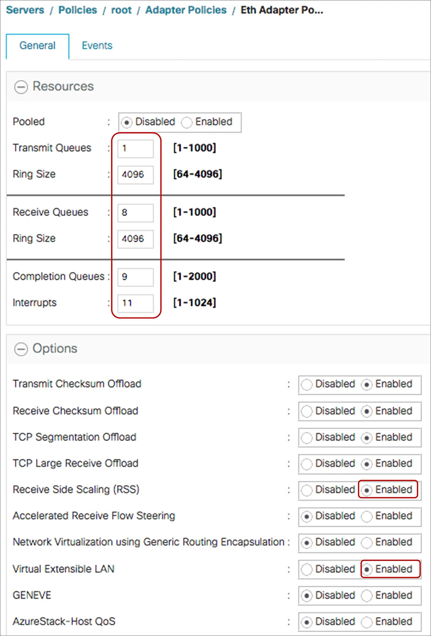
Below capture shows an adapter-policy with RSS thats applied on a vNIC from UCSM and the corresponding vmnic interface statistics from an ESXi host.
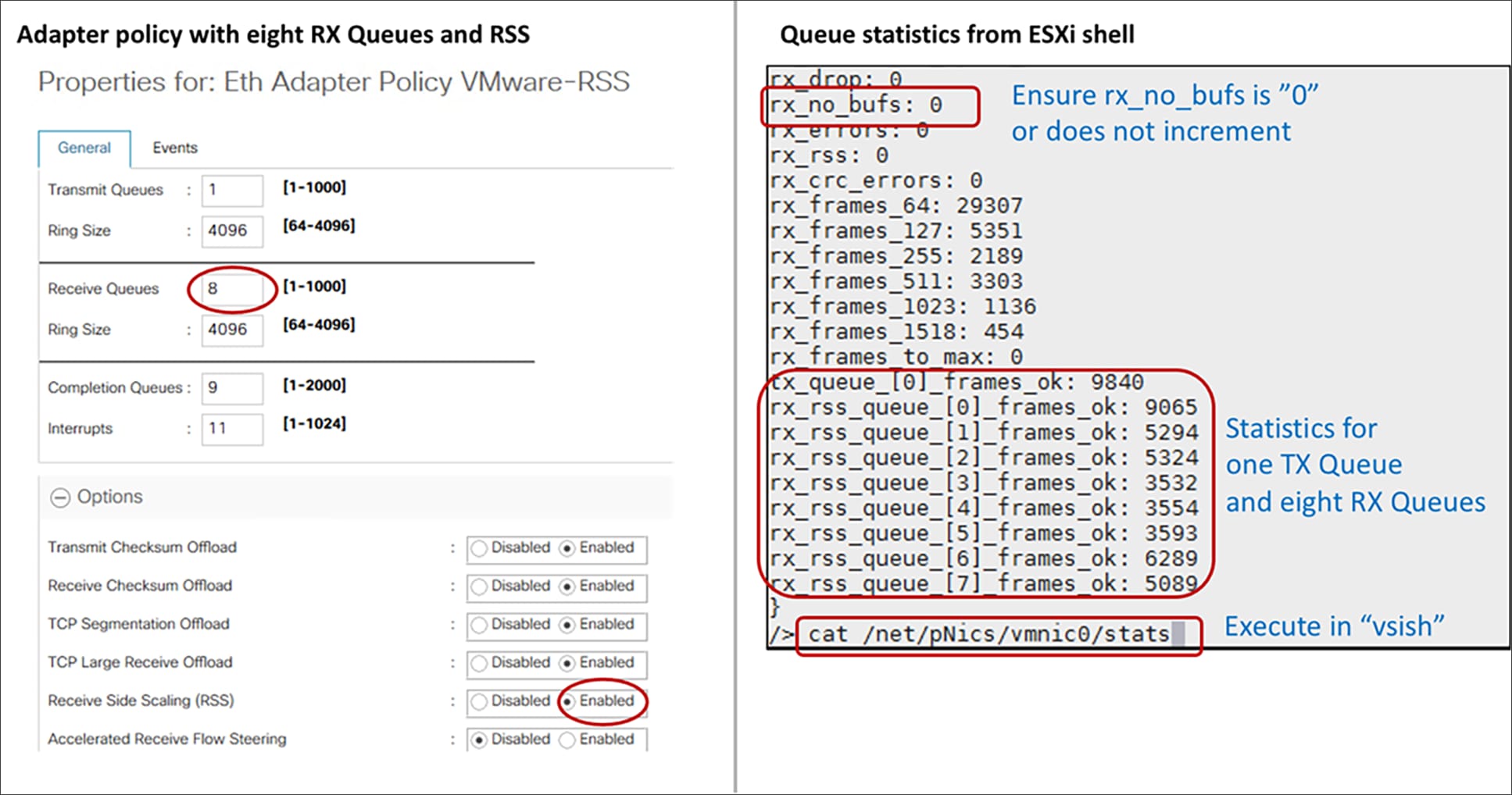
Adapter policy with RSS on ESXi host
Linux
For Linux, the following are the considerations for VIC 1400 RSS feature depending on the eNIC driver version:
Linux eNIC drivers prior to 3.2
● Supports a maximum of eight TX and eight RX queues with RSS.
● The interrupt calculation for these eNIC drivers is “TX + RX + 2.” In the above table, the value of 11 is based on this calculation.
Linux eNIC driver 3.2 and above
● Supports interrupt sharing for RX/TX queues allowing greater than eight RX and eight TX queues.
● Supports RX and TX queues up to the maximum number of CPU cores.
● Interrupt calculation would be “Maximum of (RX or TX) + 2.”
● For example, for TX = 4, RX =8, and CQ = 12, the interrupt would be 10.
● Increasing the ring-size to 4096 for handling packet drops due to slower processing by the host OS is also applicable for the Linux drivers.
● Depending on server requirements, both the TX/RX queues and the ring size can be increased.
Windows
The following are the considerations for the Windows adapter-policy with RSS on VIC 1400:
● vNIC with RSS is recommended for Windows bare-metal servers.
● While vNIC with RSS can be used for a Hyper-V host, the recommendation is to use VMMQ.
● Use the predefined Cisco UCSM adapter policy “Win-HPN” for regular RSS vNICs.
● Use the predefined “Win-HPN-SMBd” adapter policy for RDMA mode1 or ROCEv2 over PF.
● Depending on the server needs; higher throughput and better CPU utilization can be achieved using a custom adapter-policy with a higher number of RX queues and a ring size configured to a maximum of 4096.
● The maximum number of RX queues possible for a Windows adapter policy is eight; the number of TX queues cannot be more than one.
● Example values for an adapter policy with maximum values are as follows:
◦ TX queue = 1, TX ring size = 4096
◦ RX queue = 8, RX ring size = 4096
◦ CQ = 9, interrupt = 512 or at the minimum should be “2 x CPU Core + 4”.
◦ Enable RSS
● The minimum interrupt recommended to be used for VIC 1400 is “2 x CPU core + 4.” For example, for a dual-socket B200 M5 with “Intel Xeon Gold 6142” having 16 cores, the minimum interrupt would be “(2x(2x16) + 4)” or 68.
● If the need is to have a generic interrupt value in the adapter policy across servers, an interrupt value of 512 could be used.
NetQueue or VMQ on ESXi is a feature similar to the VIC RSS which can be used to achieve higher performance on Cisco UCS servers. NetQueue is an integrated hardware and software solution from both VMware and Cisco.
NetQueue achieves higher throughput and performance by having dedicated TX/RX queue per VM. So while VIC RSS is a hardware feature that enables multiple RX queues across multiple VM’s, NetQueue dedicates a TX/RX queue per VM.
Note that on VIC 1400, RSS and NetQueue for ESXi are mutually exclusive features and so either RSS or NetQueue should be used with ESXi.
NetQueue on the vNIC is enabled through the VMQ connection policy. The following are the considerations for VMQ/NetQueue with ESXi and 1400 VIC:
● When using VMQ for ESXi, there is no need to specify an adapter policy in Cisco UCSM; the default adapter policy is used.
● VIC 1400 can have a maximum of 16 VMQs per vNIC.
● Depending on the number of VMQs defined, the adapter will allocate so many (TX, RX) queues per vNIC. And each VM gets allocated a dedicated RX queue and on the transmit side, the VM traffic is distributed across multiple TX queues.
● Interrupt for VMQ is calculated as “2 x VMQ + 2.”
● If the VMNIC statistics in the ESXi host show that “rx_no_bufs” is incrementing with VMQ, the potential next step would be to increase the TX/RX queue ring sizes to 4096 using a custom adapter policy.
● Note that the adapter policy used with VMQ would specify only one TX and one RX queue, and that there is no RSS supported with an adapter policy when VMQ is used. RSS and VMQ are mutually exclusive for ESXi with VIC 1400.
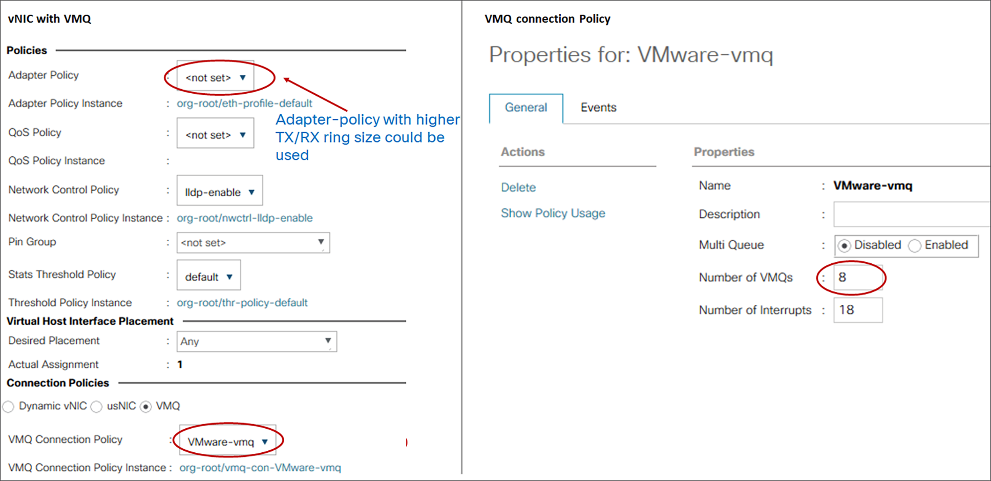
VMQ configuration on ESXi host
Queues allocated per vNIC on the ESXi host based on the VMQ configuration
The VIC 1400 can utilize RSS or NetQueue/VMQ with ESXi, and, while both provide similar performance, there are a few differentiating factors to decide on which solution suits a server’s needs:
● Traffic hashing for RSS is across Layer 2/3/4 headers whereas VMQ/NetQueue hashes based on the Layer 2 header of the packet. Thus, when a greater number of VMs above the NetQueue or VMQ configuration limit are defined in an ESXi host, RSS provides better RX traffic hashing or distribution across CPU cores.
● In scenarios involving multiple RX flows to a single VM, RSS can provide higher throughput. The reason is that for VMQ, only a single RX queue is dedicated per VM, whereas, for RSS, the traffic is distributed across all the RX queues of the vNIC.
● VMQ is to be used when an RX queue needs to be dedicated per VM. In the case of RSS, queues are not dedicated per VM.
● VMQ is helpful in scenarios where the TX performance is of concern, since, with VMQ, multiple TX queues are supported, and the traffic from a VM is distributed across multiple TX queues; whereas the adapter policies with RSS support only one TX queue. For server traffic generally, TX is never the bottleneck.
● For overlay networks built on ESXi; the VXLAN, and GENEVE offloads are available only with RSS and not with VMQ on the VIC 1400.
VMMQ, or Virtual Machine Multi-Queue, allows allocating multiple RX queues per vPort in a Hyper-V host, providing higher throughput and distributing traffic load across multiple CPU cores.
For the VIC 1400, VMMQ is supported with Windows 2016 onwards, and the recommendation for a Hyper-V host is to use VMMQ. Here are some of the considerations with VMMQ on VIC 1400:
● On Windows 2016, VMMQ is not enabled by default; VMQ is the default option. The server administrator would have to enable VMMQ using the “Set-VMNetworkAdapter” and “Set-NetAdapter” command.
● Windows 2019 supports VMMQ by default and so no explicit configuration is needed on the server.
● VMMQ assigns one TX and multiple RX queues up to a maximum of eight per vPort and is configured through the Cisco UCSM/IMC Multi-Queue (MQ) policy.
● Use of the predefined Cisco UCSM policies (“Win-HPN” and “MQ”) to enable VMMQ is recommended; and the policy definition is good for 64 vPorts.
● VMQ is a subset of VMMQ and, for VIC 1400, VMMQ is the recommended option.
● VMMQ on Windows supports VXLAN or NVGRE offload support and is enabled with the vNIC adapter policy.
Detailed configuration guidelines for VMMQ are available in the UCSM “Cisco UCS Manager Network Management Guide.”[2]
Summarizing some of these recommendations, enabling VMMQ on a vNIC in Cisco UCSM would require the following two configurations.
● Use a predefined UCSM adapter-policy “Win-HPN” or a similar custom adapter-policy in the vNIC.
● Configure a VMQ connection policy with multi-queue enabled and using a predefined UCSM MQ policy.
Below capture shows the two-step procedure to enable VMMQ on a vNIC using Cisco UCSM’s pre-defined adapter policies (Win-HPN and MQ). In the Cisco UCSM/IMC configuration window, “Sub vNIC” is the same as vPort in Hyper-V parlance. In UCSM, the predefined MQ policy is for 64 vPorts and allocates one TX and eight RX queue per vPort.
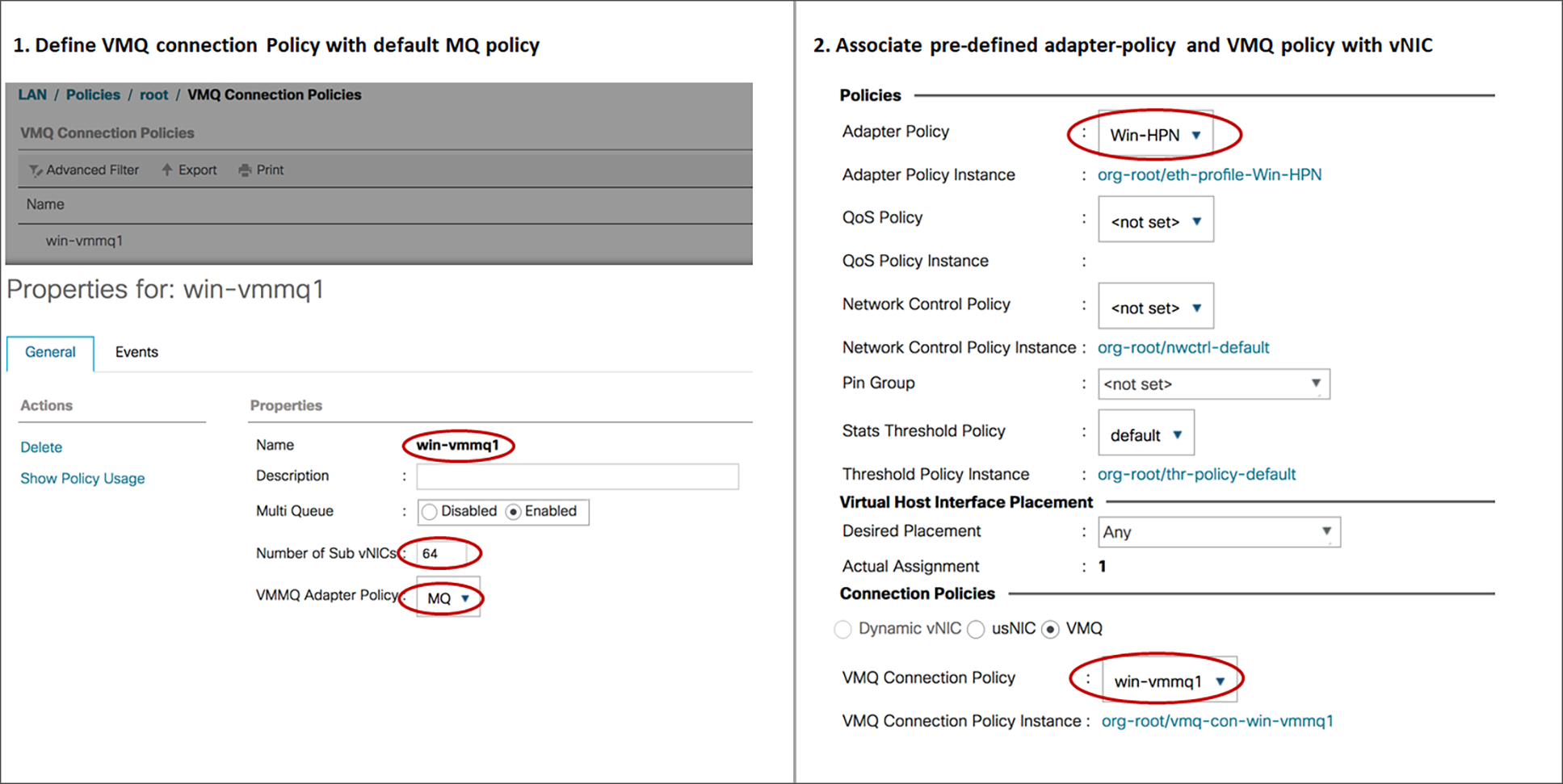
Configuring VMMQ with predefined adapter and MQ policy in UCSM
While the recommendation is to use the approach above to enable VMMQ using pre-defined UCSM adapter policies, you could also define custom VMMQ policies depending on the number of vPorts per host. The calculations for the custom MQ policy would be as follows (with the following custom MQ policy, one TX queue and eight RX queues are allocated per vPort):
● TX queue = Sub vNIC or vPort
● RX queue = 8 * (Tx Queue)
● CQ = TX + RX
● Interrupt = Max of (RX queue or atleast “2xCPU+ 4”)
● Pooled “Enabled” and RSS “Enabled.”
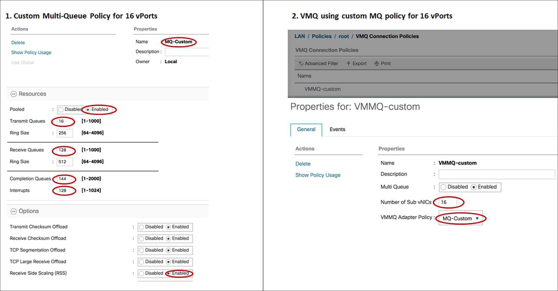
Defining custom MQ policy for 16 vPorts
The capture below is from a Hyper-V host with a single Hyper-V vSwitch and SET teaming across two vNICs. There are two VMs on the Hyper-V host with two vPorts per VM. And each vPort on the VM will get one TX and eight RX queues allocated based on the MQ policy.
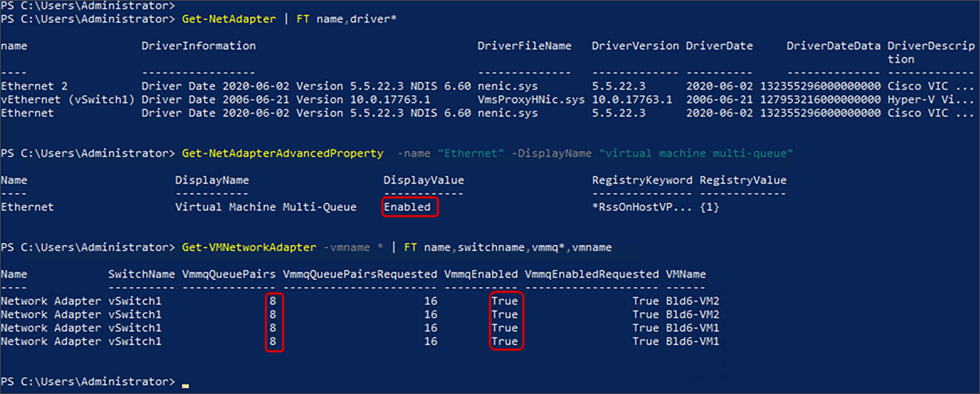
VMMQ information from a Windows 2019 Hyper-V host
The various configuration options and other details of the adapter policy not discussed here are explained in “UCSM Network Management Guide”2 which is available with each Cisco UCSM release.
Along with RSS, VMQ, and VMMQ support, another feature that VIC 1400 supports is RDMA over Converged Ethernet version 2 (RoCE v2), which is available for both Linux and Windows. The detailed configuration and recommendations for RoCEv2 are available in the “Cisco UCS Configuration Guide for RDMA over Converged Ethernet (RoCE) Version 2.”[3]
MTU setting
The other consideration to drive better performance is to have jumbo frame enabled throughout the fabric and on the servers. MTU is one of the vNIC properties that can be configured in Cisco UCSM/IMC and the recommended value for vNIC MTU is 9000.
Along with vNIC MTU, for hypervisor environments the virtualized network adapter MTU (for example, VMXNET3 for ESXi) should be configured for handling jumbo frames, with considerations for GENEVE or VXLAN headers if overlays are setup from the server.
Note that on Linux and ESXi hosts, the MTU set on the Cisco UCSM/IMC vNIC gets reflected on the host, but for the Windows servers, the MTU set on the vNIC doesn’t take effect. For Windows, the user needs to explicitly set the adapter MTU to jumbo from the Windows server.
The fourth generation VIC supports overlay offload like VXLAN, GENEVE, or NVGRE. The overlay offload on VIC enables TCP Segmentation Offload (TSO), TX/RX checksum offload for inner/outer packets, and RSS on the inner-payload of the tunneled packet. The overlay offload on VIC cards thus provides the following advantages:
● Reduced CPU utilization: Overlay offload helps to reduce CPU utilization significantly in the transmit side with TSO and TX checksum offload. And the receive side benefits from RX checksum offload.
● Better throughput: Higher throughput can be achieved by enabling overlay offload with multiple RX queues and RSS. With multiple RX-queues, RSS, and overlay offload enabled, the VIC ASIC spreads the traffic across multiple CPU cores based on the inner payload hash of the tunneled packet. Without hashing on the inner payload, traffic would be hashed based only on the outer overlay header (VXLAN/GENEVE/NVGRE). And having hash based on the inner payload provides efficient distribution across multiple CPU cores, thus achieving higher throughputs with VXLAN/NVGRE/GENEVE overlays from the server.
VXLAN offload
The VIC 1400 supports VXLAN offload with IPv4 and IPv6 payloads for ESXi, Linux, and Windows. With multiple RX queues and RSS along with VXLAN offload enabled, packets can be load balanced across multiple CPU cores based on the inner payload.
The recommended adapter policy with VIC 1400 for VXLAN overlays is to have the following:
● Multiple RX queues with RSS enabled
● TX/RX queue-size of 4096
● VXLAN offload enabled
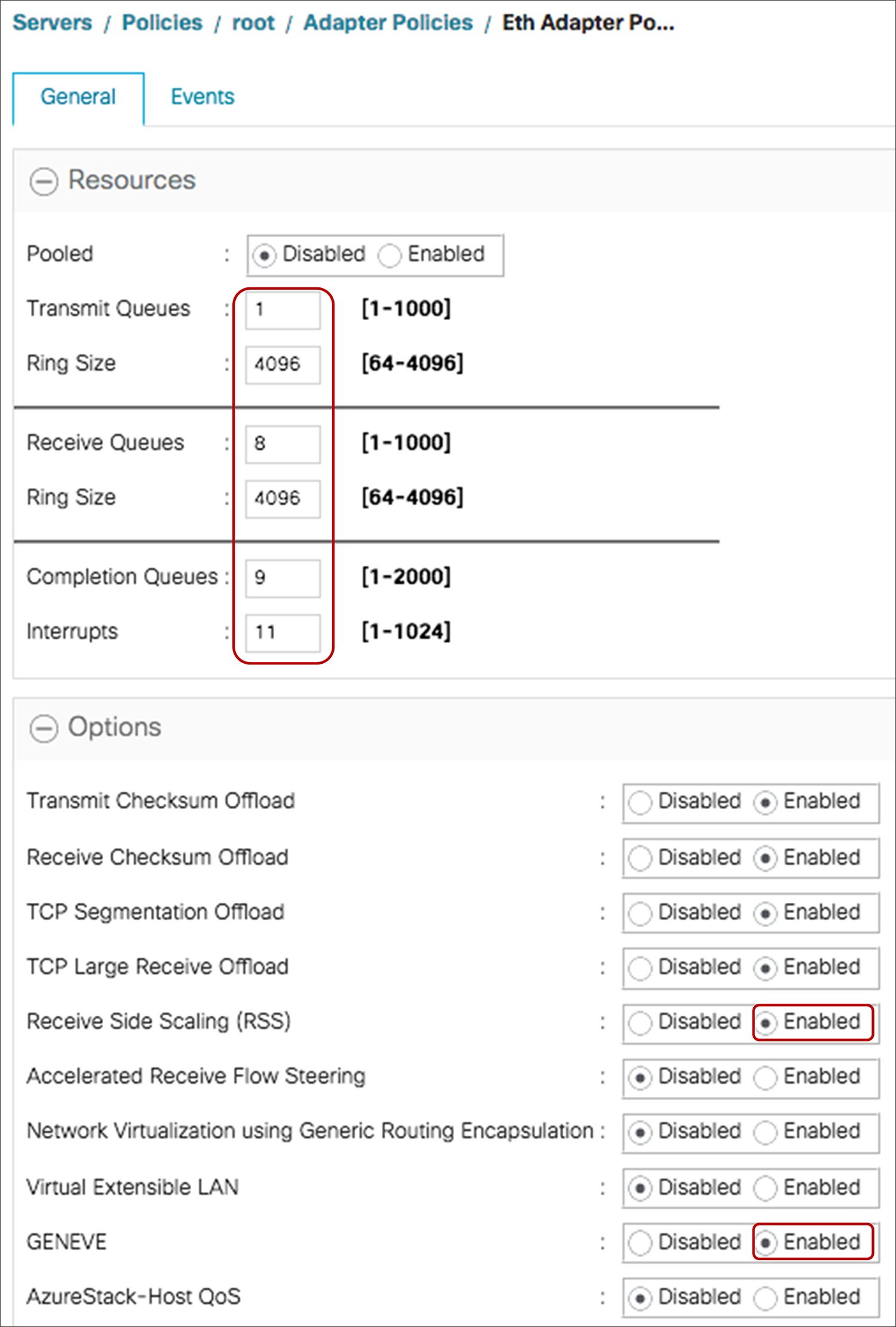
VXLAN offload recommended adapter-policy for VMware
For VMware, VXLAN offload is supported only with RSS and not with VMQ or NetQueue.
The above defined adapter-policy for VMware is applicable for Linux too; please note that VXLAN offload is different from OVS offload and OVS offload is not supported in VIC.
For Hyper-V environments VMMQ is the recommended solution to be used with VXLAN offload.
Additionally, on Windows, NVGRE offload is also supported on the VIC 1400, but the most commonly deployed, and the Windows, recommendation is VXLAN offload.
GENEVE offload
GENEVE Offload on the fourth-generation VIC is supported for VMware ESXi starting from Cisco UCSM and Cisco IMC release 4.1(2) and the VIC is certified for NSX-T with GENEVE offload.
GENEVE offload on the VIC 1400 supports the NSX-T vSwitch (N-VDS or VDS 7) in “standard mode” from Cisco UCSM and Cisco IMC Release 4.1(2) and the NSX-T vSwitch in “enhanced datapath mode” from Cisco UCSM and Cisco IMC Release 4.1(3).
Please refer the Cisco UCS release-notes for the supported ESXi versions across releases.
GENEVE offload for N-VDS in standard mode
GENEVE offload for the standard mode is supported on VIC 1400 with RSS to provide better CPU utilization and higher throughput. In this mode, VIC 1400 would provide RSS on inner packet, TSO for IPv4/v6 packets, and TX/RX checksum offload for IPv4/v6 inner/outer packet.
The recommended settings are as follows:
● Multiple RX queues with RSS
● TX/RX queue size of 4096
● Enable GENEVE offload
Included below is the adapter policy required for enabling N-VDS in standard mode. Additionally, on NSX-T the user would create a NSX-T vSwitch in standard mode.
GENEVE offload–enabled adapter policy for standard N-VDS vSwitch
GENEVE offload for N-VDS in enhanced datapath mode
GENEVE offload support on the VIC 1400 for the enhanced datapath mode on the NSX-T vSwitch is available from Cisco UCSM and IMC Release 4.1(3). Enhanced datapath mode or alternatively called ENS on ESXi uses DPDK-like techniques to provide higher throughput. Notably, ENS utilizes polling to achieve high packet rates. When ENS is enabled, vSwitch uses the VMware ENS stack and utilizes the VIC ENS driver for its uplink ports.
In this case, VIC 1400 would provide support of enhanced datapath mode, TSO for IPv4/v6 and GENEVE, and TX/RX checksum offload for IPv4/v6 inner/outer packets.
Geneve offload with ENS on VIC 1400 would require an additional “nenic-ens” driver to be installed and depending on the NSX-T vSwitch (standard or ENS) the appropriate driver (nenic or nenic-ens) gets enabled. Note that there is no RSS support on VIC 1400 for Geneve offload with ENS.
The recommended adapter policy settings for Geneve offload with ESXi ENS are as follows:
● Single TX/RX queue
● TX/RX queue size of 4096
● Enable GENEVE offload
Included below is the adapter policy required for enabling NSX-T vSwitch in enhanced datapath mode. Additionally, on the NSX-T, the user needs to select the creation of NSX-T vSwitch in enhanced datapath mode.
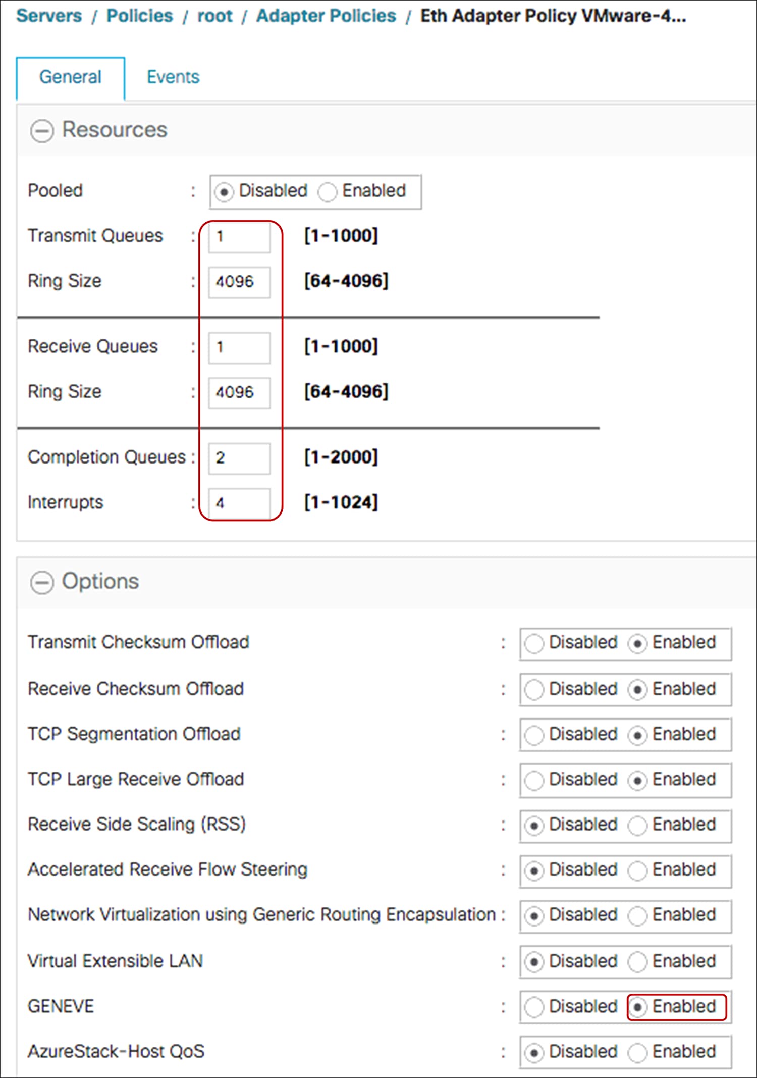
GENEVE offload–enabled adapter policy for enhanced datapath mode N-VDS vSwitch
3. Forward Error Correction settings on 1455/1457/1495/1497
Forward Error Correction (FEC) is a method of obtaining error control in data transmission over an unreliable or noisy channel in which the source (transmitter) encodes the data in a redundant way using Error Correcting Code, and the destination (receiver) recognizes it and corrects the errors without requiring retransmission.
A Forward Error Correction (FEC) setting for a VIC 1455/1457 is applicable at 25Gbps, and for a VIC 1495/1497 at 100Gbps. These FEC settings on VIC 1455/1457/1495/1497 are applicable only for standalone rack-servers and are configurable through Cisco Integrated Management Controller (IMC). For UCSM-managed rack-servers, the FEC settings are auto-determined based on the inserted transceiver and the fec settings are not configurable.
The FEC configuration on a VIC 1455/1457 port at 25Gbps could be either of the following:
● Auto: Default setting until Cisco IMC Release 4.1(2) for 25G.
This sets the FEC to RS-FEC (CL91); from Cisco IMC Release 4.1(2) and the “Auto” option is removed.
● RS-FEC (CL91): The new default from Cisco IMC Release 4.1(2)
● FC-FEC (CL74)
● FEC off
FEC configuration on a VIC 1495/1497 port at 100G could be either of the following:
● Auto: Default until Cisco IMC 4.1(2); and sets FEC to RS-FEC (CL91).
● RS-FEC (CL91): New default from Cisco IMC Release 4.1(2); this will work for all transceivers/cables except for QSFP-100G-LR4-S or QSFP-40/100-SRBD transceivers.
● FEC off: Needed for QSFP-100G-LR4-S or QSFP-40/100-SRBD transceivers
For the link between a VIC and a switch/router to be “up,” the FEC settings have to match on both ends. To arrive at a common fec setting on both the VIC and switch ports, these following factors have to be taken into consideration:
● Transceiver type: Some transceivers have minimum FEC requirements; for example, 25G-SR-S optics have a minimum FEC requirement of RS-FEC or CL91.
● Cable: Cables have a minimum FEC requirement depending on their length.
● Switch: FEC settings for 25/50/100G are based on IEEE and Ethernet-consortium standards. A switch/router can have FEC configuration options depending on the supported standards; also, the switch ports can have different default FEC settings, such as FC-FEC (CL74) or RS-FEC (CL91).
● VIC: On a VIC the ports are set to RS-FEC or CL91 by default. Also, the VIC doesn’t support autodetection of FEC for copper cables.
Due to the difference in the minimum required FEC across cables/transceivers and the switches, the user needs to ensure that the FEC values should be supported by the cables/transceivers and configure them identically on the switch/router interfaces and VIC ports.
The following FEC configuration guidelines are for a VIC 1455/1457 connected at 25Gbps to Cisco Nexus 9200/9300 switches using the standalone NX-OS build. But this can be used as a reference for other switches too. The FEC configuration on the switch port and on the VIC should be identical and configured to at least the minimum FEC or a value above it.
Table 4. FEC guideline based on cable, transceiver, switch and VIC
| Cable/transceiver PID |
Min FEC for cable/ transceiver |
Default on Cisco Nexus 9200/9300 (NX-OS) |
Default on VIC 1455/1457 |
Min FEC configuration on switch and VIC |
| SFP-H25G-CU1M/1.5M/2M |
None |
CL74 (FC-FEC) |
CL91 (RS-FEC) |
None |
| SFP-H25G-CU2.5M/3M |
FC-FEC |
CL74 (FC-FEC) |
CL91 (RS-FEC) |
CL74 |
| SFP-H25G-CU4M/5M |
RS-FEC |
CL74 (FC-FEC) |
CL91 (RS-FEC) |
CL91 |
| SFP-25G-AOCxM |
FC-FEC |
CL74 (FC-FEC) |
CL91 (RS-FEC) |
CL74 |
| SFP-25G-SR-S |
RS-FEC |
CL74 (FC-FEC) |
CL91 (RS-FEC) |
CL91 |
| SFP-10/25G-CSR-S, 0-30M/50M, OM3/4 |
None |
CL74 (FC-FEC) |
CL91 (RS-FEC) |
None |
| SFP-10/25G-CSR-S, 30/50M to 70/100M, OM3/4 |
FC-FEC |
CL74 (FC-FEC) |
CL91 (RS-FEC) |
CL74 |
| SFP-10/25G-CSR-S, above 70/100M, OM3/4 |
RS-FEC |
CL74 (FC-FEC) |
CL91 (RS-FEC) |
CL91 |
| SFP-10/25G-LR-S |
RS-FEC |
CL74 (FC-FEC) |
CL91 (RS-FEC) |
CL91 |
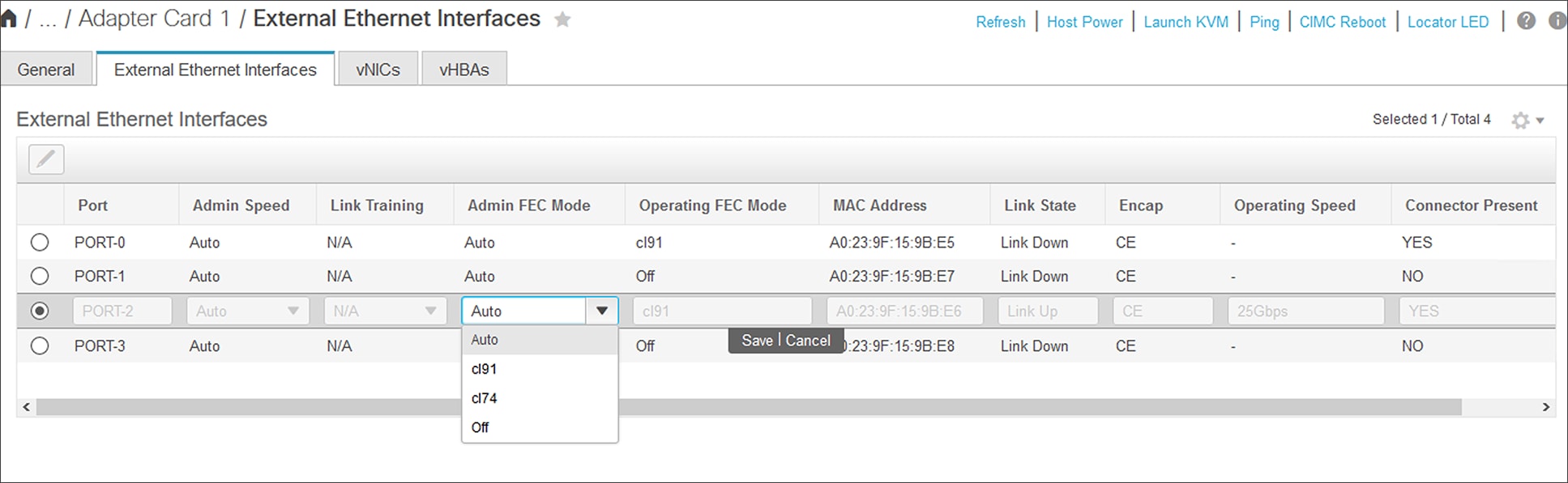
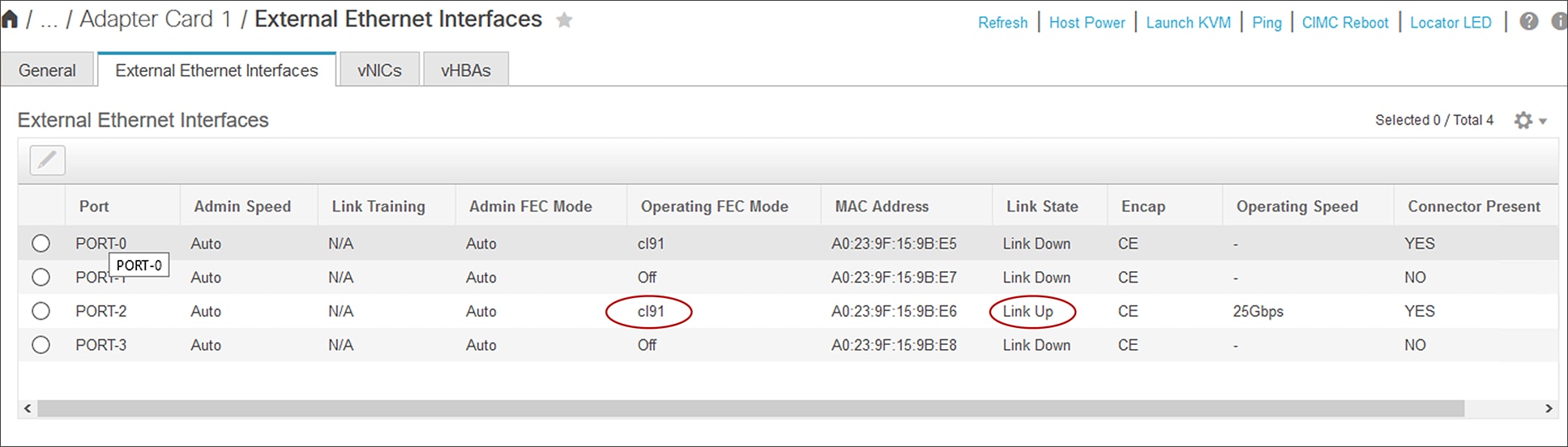
FEC configuration and validation for a VIC 1457 port from Cisco IMC
4. Rack-server connectivity with VIC 1455/1457
VIC 1455/1457 are quad-port 10/25G VIC cards designed for the Cisco UCS C-Series Rack Servers. The card supports 10/25-Gbps Ethernet or FCoE.
By default, the VIC 1455/1457 ports (1, 2) and (3, 4) are in a hardware port-channel on the VIC ASIC. The hardware port-channel on the VIC 1455/1457 provides link-level redundancy and higher bandwidth, and the OS can potentially see a maximum of 50Gbps vNICs on the adapter. For efficient load balancing, the traffic from the server is hashed across the VIC hardware port-channel using Layer 2, Layer 3 and Layer 4 fields in the packet. Note that this VIC hardware port-channel doesn’t support LACP.
In UCSM mode, there is no option to disable the VIC hardware port-channel, so the VIC ports (1,2) and (3,4) are always in a port-channel when connected to a fabric interconnect. While in standalone-mode when the VIC 1455/1457 are connected to a Cisco or a third-party switch/router, the default hardware port-channel can be disabled from Cisco IMC.
Depending on whether the VIC hardware port-channel is enabled or disabled the vNIC speed seen on the server would be different and the behavior would be as follows:
● With the default port-channel enabled, each vNIC on a VIC 1455/1457 will pin to a VIC hardware port-channel, and each vNIC will have the speed of the active port-channel members combined. Please note that each VIC 1455/1457 port supports either 10Gbps or 25Gbps, so, accordingly, the port-channel and vNIC speed could be 10G, 20G, 25G or 50G. Depending on whether it’s a 10G or 25G link and how many links are active.
● On disabling port-channel, each vNIC can pin to one of the four VIC external ports, and each vNIC will be 10Gbps or 25Gbps depending on the inserted transceiver.
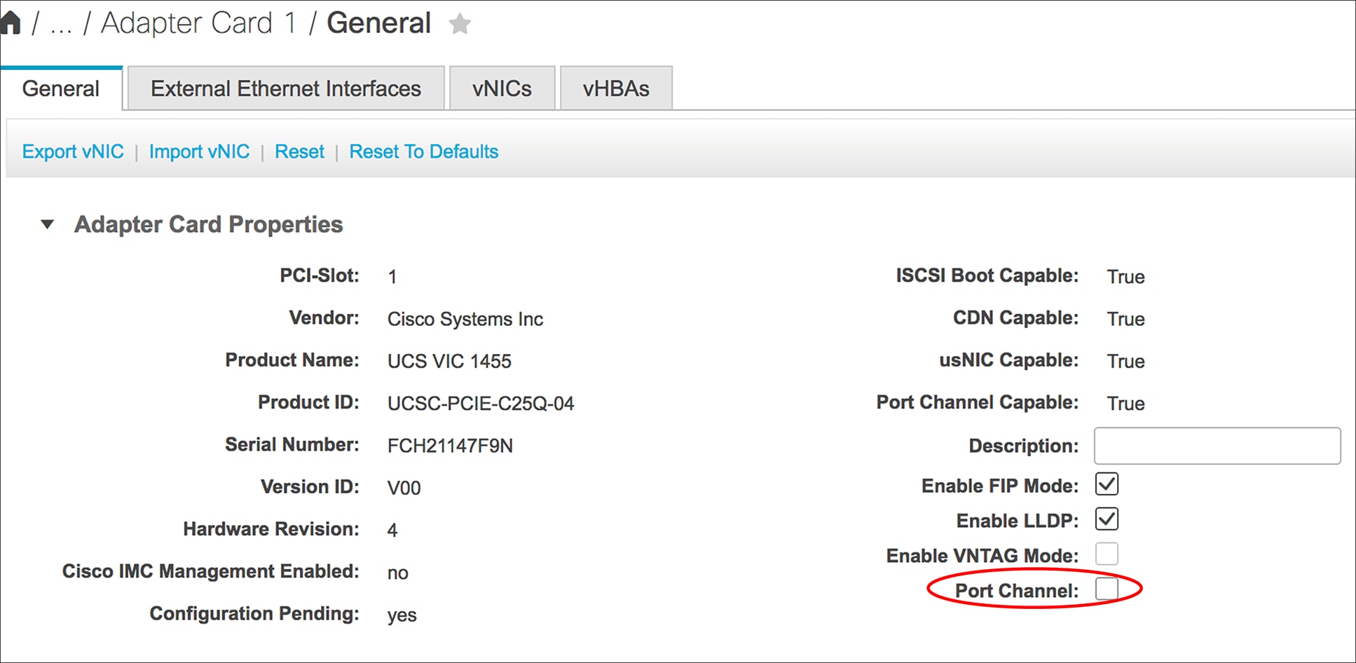
Disabling default port-channeling from Cisco IMC
The various connectivity options with VIC 1455/1457 are as follows:
● In UCSM mode, connect VIC 1455/1457 ports 1/2 or both to FI-A and port 3/4 or both to FI-B. When VIC 1455/1457 are connected to fabric interconnect, the NX-OS software takes care of automatically provisioning a port-channel on the FI-A and FI-B.
● In standalone mode with port-channel mode enabled on VIC 1455/1457, connect VIC ports 1/2 or both to one Top-of-Rack (ToR) switch and ports 3/4 or both to the other ToR switch.
When both VIC ports in (1,2) or (3,4) are connected to a ToR switch, one would have to configure a non-lacp port-channel on the ToR switch.
● In standalone mode with port-channel mode disabled, the VIC 1455/1457 ports could be connected to ToR switches in any order.
The above connectivity options are detailed below and note that, in the diagrams below, dotted lines represent optional connections or an optional port-channel configuration. The connectivity options shown below are applicable for VIC 1457 (MLOM) and VIC 1455 (PCIe).
The diagrams depict physical connectivity and not the various NIC teaming options that are possible from an Operating System (OS) perspective.
VIC 1455/1457 connectivity to fabric interconnect
When connected to a Fabric Interconnect (FI), the VIC ports (1, 2) and (3, 4) are always in port-channel mode and cannot be disabled. Ensure the connectivity toward the FI is done taking into consideration the hardware port-channel. Always connect port (1,2) to one fabric interconnect and ports (3,4) to the other FI.
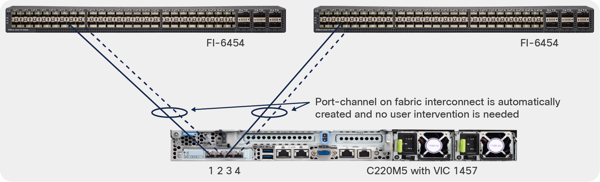
UCSM mode ports (1, 2) connect to one FI and ports (3, 4) to the other FI
VIC 1455/1457 connectivity on standalone server
In standalone mode or when the Cisco UCS server is managed through Cisco IMC, the default port-channeling can be enabled or disabled. And depending on this one needs to handle the VIC to ToR switch physical connections as well as the OS teaming and upstream ToR switch port/port-channel configuration.
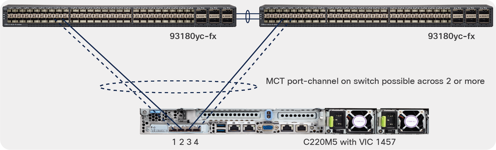
Default VIC port-channel enabled on standalone server
With default VIC port-channel enabled, switch dependent OS teaming/bonding from the server is possible only with single-link from VIC 1455/1457 toward each ToR switch as shown below. Ensure that VIC 1455/1457 ports 1 or 2 connects to one ToR switch and the VIC ports 3 or 4 connects to the other ToR switch.
And in this case a common deployment would be to have the ToR switches, in a multi-chassis trunking (MCT) pair, like shown below. Examples of MCT are Virtual Port Channel (VPC) from Cisco or mLAG supported on third-party switches.
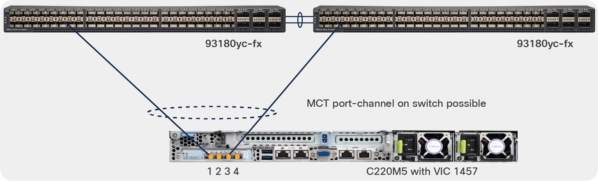
Standalone mode server connectivity with HW port-channels on VIC and MCT port-channel possible with single-links to each ToR
With VIC 1455/1457 hardware port-channel enabled, if one wants to use all four ports of VIC 1455/1457 to connect towards a ToR switch pair like in the diagram below. Ensure that VIC 1455/1457 ports 1 and 2 connect to one ToR switch and ports 3 and 4 connects to the other ToR switch.
Now with dual-links toward each ToR switch and with default VIC HW port-channel enabled, a switch- dependent OS teaming is not possible from the server.
In this case, on each of the ToR switch, a non-LACP port-channel would have to be created, and a VPC-like MCT port-channel spanning multiple ToR switches is not possible.
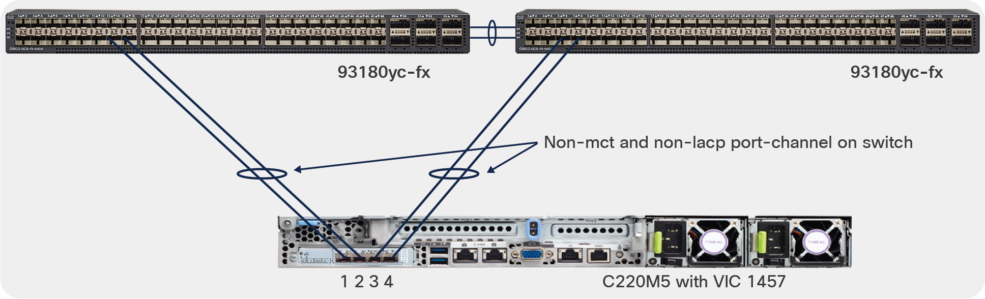
Standalone mode server connectivity with default port-channeling enabled and two links to each ToR
Default port-channel disabled
With VIC 1455/1457 hardware port-channeling disabled, a switch-dependent OS teaming/bonding on the server is possible across all ports with ToR switches in MCT. Switch-dependent port-channels can span across all four ports of the VIC 1455/1457, or they can be connected to two different MCT switch pairs, as shown below. There is also no dependency, on how the four ports of the VIC 1455/1457 should be connected to the upstream ToR switches.
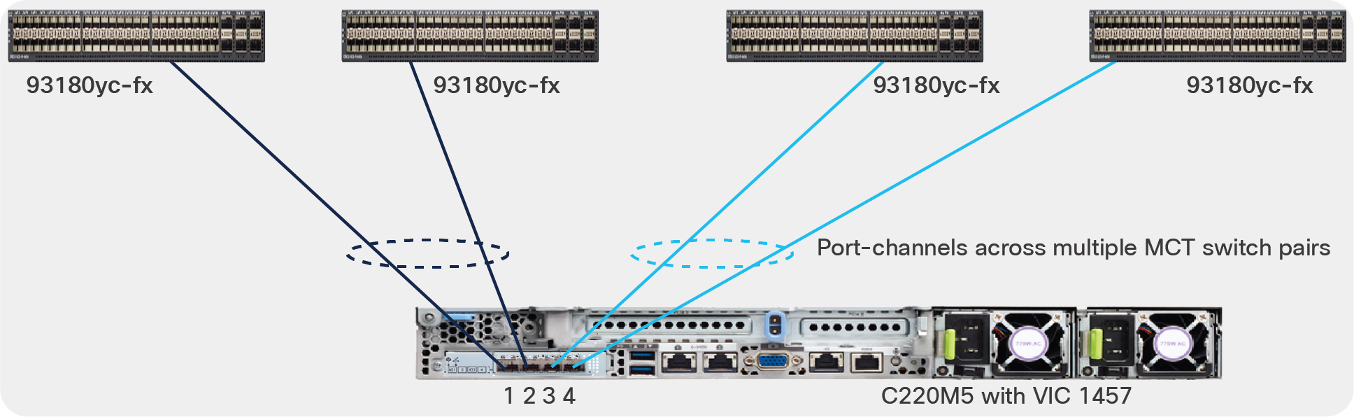
Standalone mode server connectivity with default port-channeling disabled
5. Priority-tagging on VIC with standalone rack-server
VIC 1455/1457/1495/1497 have priority-tagging enabled for QoS and the priority-tagging cannot be disabled in Cisco UCS VIC. Due to this, by default, the untagged traffic from the server will always be sent by the VIC with a VLAN tag “0” for COS to the upstream switch/router.
This needs to be taken into consideration when connecting the VIC in a standalone rack-server, to a third-party switch or a non-nexus Cisco switch. Since the upstream ToR switch/router that the VIC connects to may or may-not support priority-tagging.
Before going into details of how to handle this, here are some additional configuration options on the Cisco IMC for vNIC’s one should be aware of:
● By default, in standalone mode, no “default-vlan” is configured under the vNIC properties in Cisco IMC. And in this case the untagged traffic from the server will be tagged with VLAN 0 and sent towards upstream ToR switch/router.
● If “default-vlan” is configured under the vNIC, then the untagged traffic from the server will be tagged with that VLAN and sent to the upstream ToR switch/router.
Following behavior is to be expected depending on whether priority-tagging is supported or not on the upstream switch:
● If the upstream switch supports priority tagging, then the upstream switch’s port and the vNIC should work seamlessly. Please note that, by default, the vNICs are in trunk mode, and the “Default-VLAN” under vNIC properties is none.
● If the upstream switch doesn’t support priority tagging, then the vNIC has to be configured as a trunk with a default VLAN. With a default VLAN configuration on the vNIC, the untagged traffic from the server will be sent on this VLAN by the VIC toward the upstream switch. And on the upstream switch port, this default VLAN on vNIC should be configured using a “switchport trunk native vlan <vlan-id>” Cisco NX-OS equivalent configuration.
Please note that the untagged packets from a server, such as LACP, which are to be processed by the supervisor or control plane on the switch/router, are sent by the VIC in the “VLAN-0” or the “default VLAN” of the vNIC if it is configured. So even if some switches/routers support priority-tagging, they ignore processing of control plane bound packets on this vlan. And in such cases LACP cannot be used.
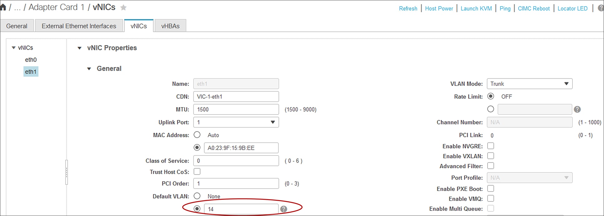
Default VLAN configuration under vNIC from Cisco IMC
Read more about Cisco UCS products:
https://www.cisco.com/c/en/us/products/servers-unified-computing/index.html
Read more about the Cisco UCS VIC 1400:
https://www.cisco.com/c/en/us/products/collateral/interfaces-modules/unified-computing-system-adapters/datasheet-c78-741130.html
https://www.cisco.com/c/dam/en/us/products/collateral/servers-unified-computing/ucs-b-series-blade-servers/whitepaper_c11-740098.pdf
https://www.cisco.com/c/en/us/td/docs/unified_computing/ucs/ucs-manager/GUI-User-Guides/Network-Mgmt/4-1/b_UCSM_Network_Mgmt_Guide_4_1/b_UCSM_Network_Mgmt_Guide_4_1_chapter_01010.html
https://www.cisco.com/c/en/us/td/docs/unified_computing/ucs/ucs-manager/GUI-User-Guides/RoCEv2-Configuration/4-1/b-RoCE-Configuration-Guide-4-1.html