What are breakouts and how do you use them?
Available Languages
Bias-Free Language
The documentation set for this product strives to use bias-free language. For the purposes of this documentation set, bias-free is defined as language that does not imply discrimination based on age, disability, gender, racial identity, ethnic identity, sexual orientation, socioeconomic status, and intersectionality. Exceptions may be present in the documentation due to language that is hardcoded in the user interfaces of the product software, language used based on RFP documentation, or language that is used by a referenced third-party product. Learn more about how Cisco is using Inclusive Language.
Recent advancements in network connectivity using breakout mode are becoming increasingly important as new high-speed ports become available on switches, routers, and other communication equipment. Breakouts allow these new ports to interface with lower-speed ports.
Breakouts enable connectivity between network devices with different speed ports, while fully utilizing port bandwidth.
Breakout mode on network equipment (switches, routers, and servers) opens up new ways for network operators to keep up with the pace of bandwidth demand. By adding high-speed ports that support breakout, operators can increase faceplate port density and enable upgrade to higher data rates incrementally.
Breakout mode is when a high-speed, channelized port on a network element is broken down into multiple low-speed ports, each going to multiple network elements. For example, a switch with 400G ports can be connected to 100G ports.
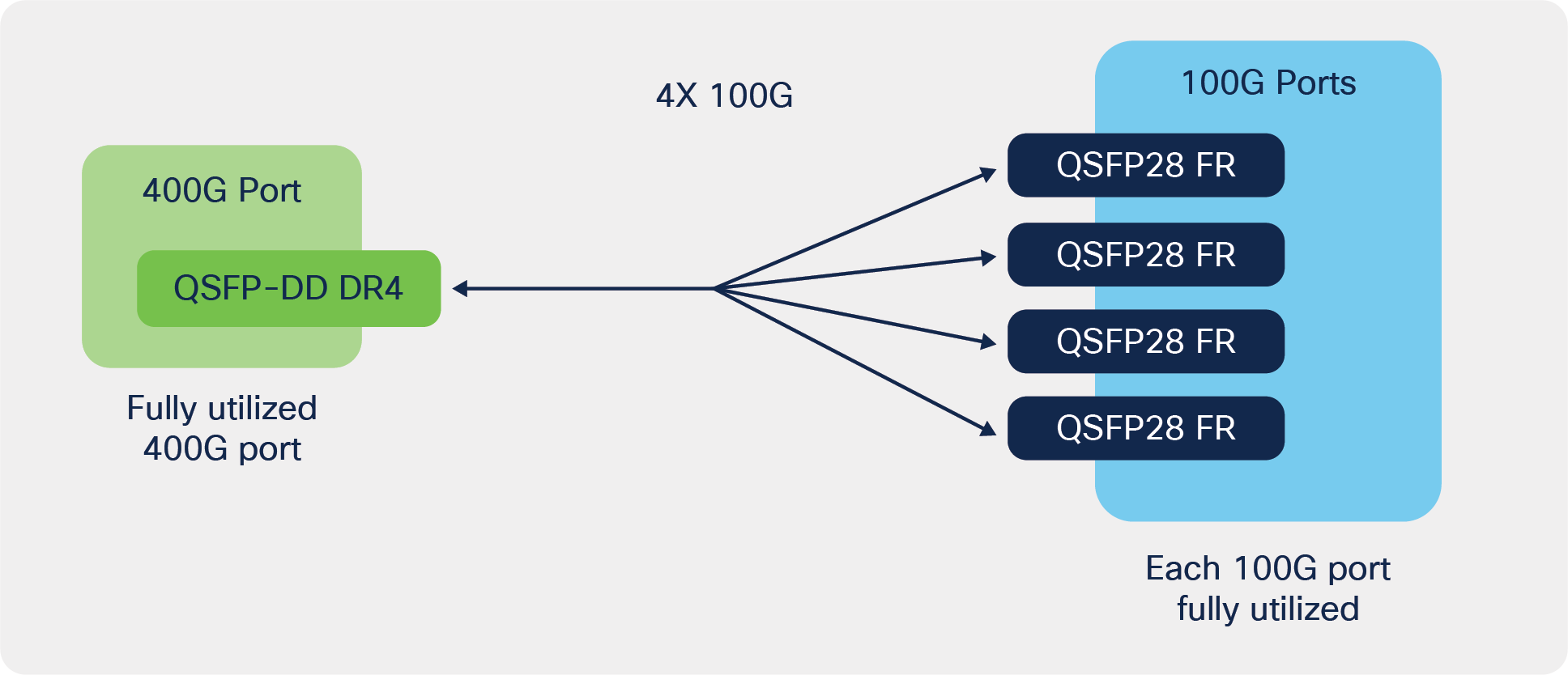
400G to 100G breakout
Breakout always involves the connection of a channelized port to multiple unchannelized or channelized ports. Channelized ports are always implemented in multilane form factors, such as QSFP+, QSFP28, QSFP56, QSFP28-DD, and QSFP56-DD. Typically, unchannelized ports are implemented in single-channel form factors, including SFP+, SFP28, and future SFP56. Some port types, such as QSFP28, can be on either side of the breakout, depending on the situation.
Today, channelized ports include 40G, 100G, 200G, 2x100G, and 400G and unchannelized ports include 10G, 25G, 50G, and 100G as shown in Table 1.
Table 1. Breakout Capable Transceivers
| Rate |
Technology |
Breakout Capable |
Electric Lanes |
Optical Lanes* |
| 10G |
SFP+ |
No |
10G |
10G |
| 25G |
SFP28 |
No |
25G |
25G |
| 40G |
QSFP+ |
Yes |
4x 10G |
4x10G, 2x20G |
| 50G |
SFP56 |
No |
50G |
50G |
| 100G |
QSFP28 |
Yes |
4x 25G |
100G, 4x25G, 2x50G |
| 200G |
QSFP56 |
Yes |
4x 50G |
4x50G |
| 2x 100G |
QSFP28-DD |
Yes |
2x (4x25G) |
2x (4x25G) |
| 400G |
QSFP56-DD |
Yes |
8x 50G |
4x 100G, 8x50G |
Generally, for breakout transceivers, the optical lanes equal the electrical lanes; however, some transceivers have gearboxes that enable rate conversion and thus the optical lanes are reduced. For example, the new QSFP-28 100G single lambda transceivers have 1 optical lane of 100G, and the ASIC in the transceiver converts from 4 lanes of NRZ @ 25 GHz electrical to 1 lane of PAM4 @ 50 GHz optical.
Also, some multilane transceivers are incapable of breakout because of limitations of the implementation of the ASIC in the transceiver. For example, there could be only a single CDR (Clock Data Recovery) circuit for a single lane in a multilane transceiver, thus preventing channelized operation.
In addition, some transceivers utilize multiple optical wavelengths on a single fiber and breakout isn’t offered because of the complexities of optical muxing/demuxing, including power level imbalances and because it hasn’t been tested.
Also, some transceivers like the QSFP-100G-SR-BD and QSFP-40G-SR-BD don’t have breakout capability even though they have 2x50G (2x25G-PAM4) and 2x20G optical lanes that operate on duplex fiber, because they weren’t designed for breakout.
What types of breakout options are available?
Breakout is physically implemented with cables or transceivers. Some of the options include breakout DACs, breakout AOCs, and transceivers.
Breakout DACs
Direct Attached Cables (DACs) are fixed length and made of multiple copper twinax cables. They are generally 1 to 5 m long in passive configuration and 7 to 10 m long in active configuration and include the modules that plug into the equipment ports as shown in Figure 2.
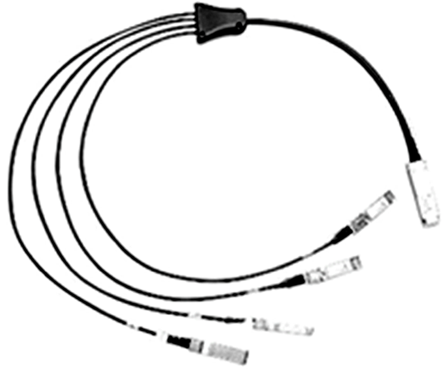
Breakout DAC
Breakout AOCs
Active Optical Cables (AOCs) are fixed length and made of multiple optical cables, generally 1 to 25 m long, and include the modules that plug into the equipment ports as shown in Figure 3.
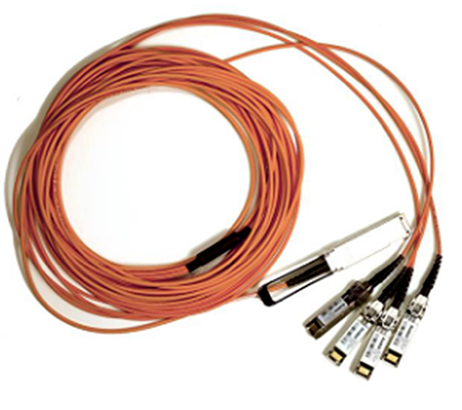
Breakout AOC
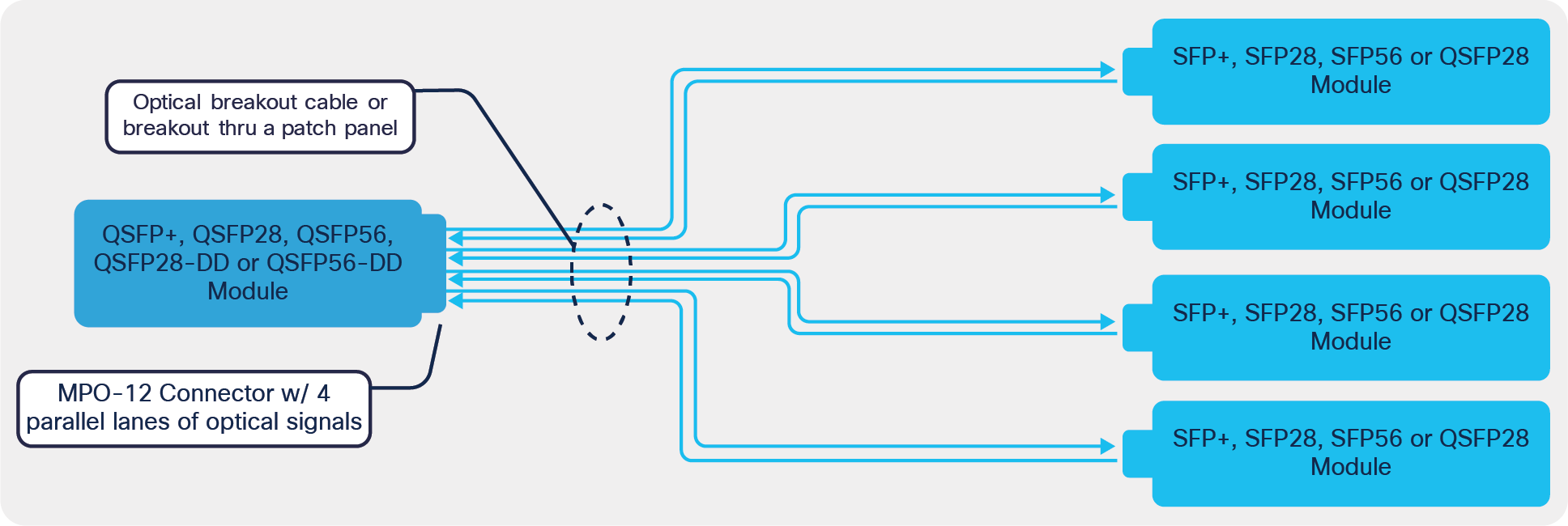
Transceivers
Transceivers could use either Single-Mode Fiber (SMF) or Multimode Fiber (MMF) when paired with a breakout cable as shown in Figure 4.
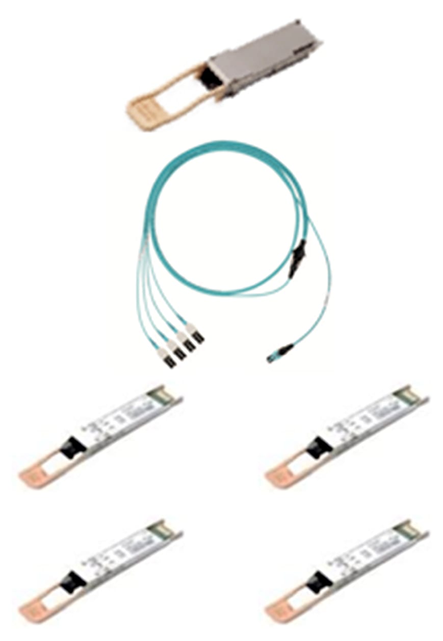
Transceivers for breakout
Which pluggable optics support breakout?
Examples of transceivers used in breakout applications are as follows.
For MMF applications:
● QSFP-40G-SR4 to 4x SFP-10G-SR
● QSFP-40G-CSR4 to 4x SFP-10G-SR
● QSFP-100G-SR4 to 4x SFP-25G-SR
● QDD-2x100G-SR4 to 2x QSFP-100G-SR4
For SMF applications:
● QSFP-4x10G-LR4 to 4x SFP-10G-LR
● QSFP-100G-PSM4 to 4x SFP-25G-LR
● QDD-2x100G-LR4 to 2x QSFP-100G-LR4
● QDD-2x100G-CWDM4 to 2x QSFP-100G-CWDM4
● QDD-400G-DR4 to 4x QSFP-100G-DR
● QDD-4x100G-FR to 4x QSFP-100G-FR
● QDD-4x100G-LR to 4x QSFP-100G-LR
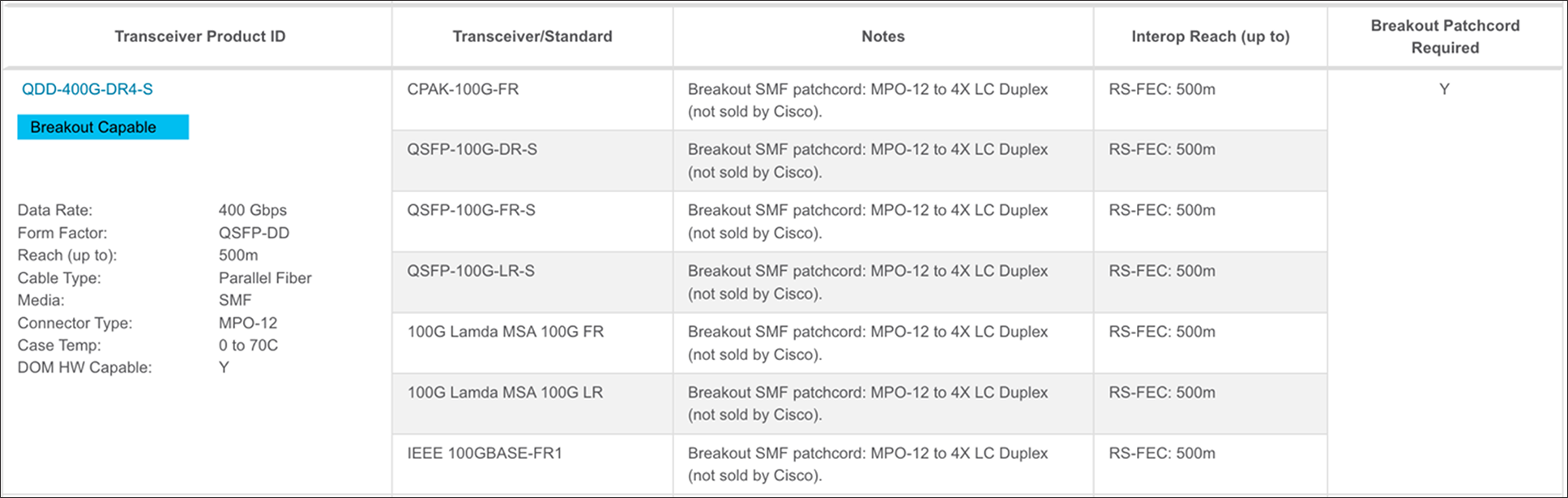
For a full list and mapping of which optics can connect to each other via breakout, see the Optics-to-Optics Interoperability Matrix. Below is an example.
Table 2. Optics-to-optics interoperability matrix
Fiber optic breakout diagrams and transceiver pinouts
If your fiber cable vendor doesn’t have a standard breakout patch cord, and you request a custom design, you can use the diagram below as a guide. The patch cord doesn’t depend on the data rate. The main consideration is whether the fiber type is SMF or MMF.
For the QSFP-40G-SR4, QSFP-40G-CSR4, QSFP-4x10G-LR-S, QSFP-100G-SR4-S, QSFP-100G-PSM4-S, CPAK-100G-SR4, CPAK-100G-PSM4, QDD-400G-SR4.2-BD, QDD-400G-DR4-S, QDD-4x100G-FR-S, QDD-4x100G-LR4-S, and QSFP-200G-SR4, these transceivers utilize MPO-12 (Multifiber Push On) connectors for breakout as shown in the following diagram.
Transceivers that MPO-12 used for breakout
The physical connections are as follows.
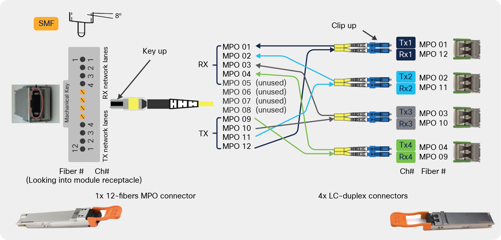
Schematic of MPO-12 for breakout
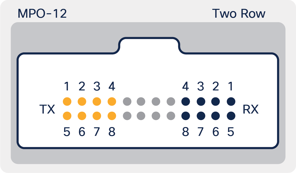
Figure 6 shows the fiber breakout jumper pinout diagram for SMF or MMF applications using MFO connectors. Note the 8-degree angle polish on the MPO connector end face for SMF applications.
The transmit and receive of the optical lanes of the MPO-12 interface occupy the positions depicted in the following figure when looking into the module receptacle with the connector keyway feature on top.
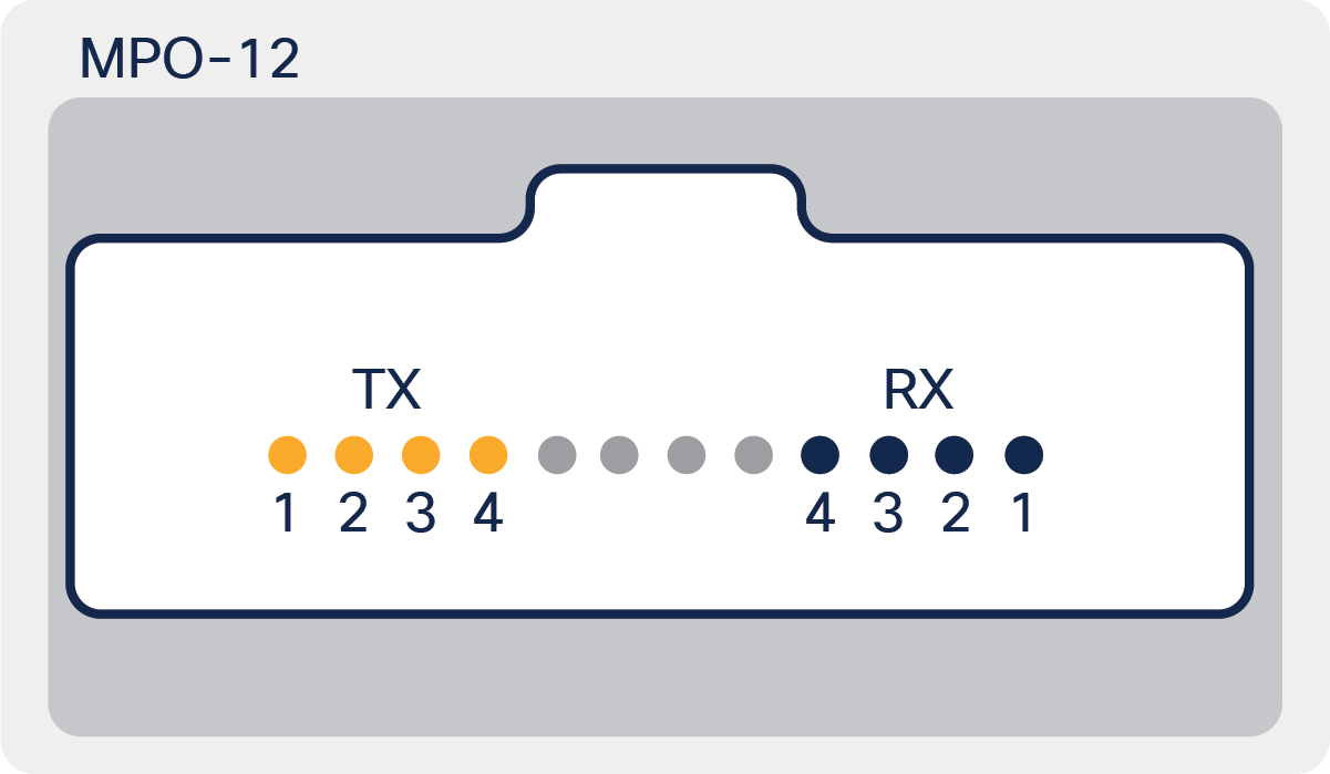
Pinout for MPO-12
For the QDD-2X100G-SR4-S, the transceiver utilizes the MPO-24 (known as the Two-Row MPO-12) connector for breakout to 2x QSFP-100G-SR4-S modules.
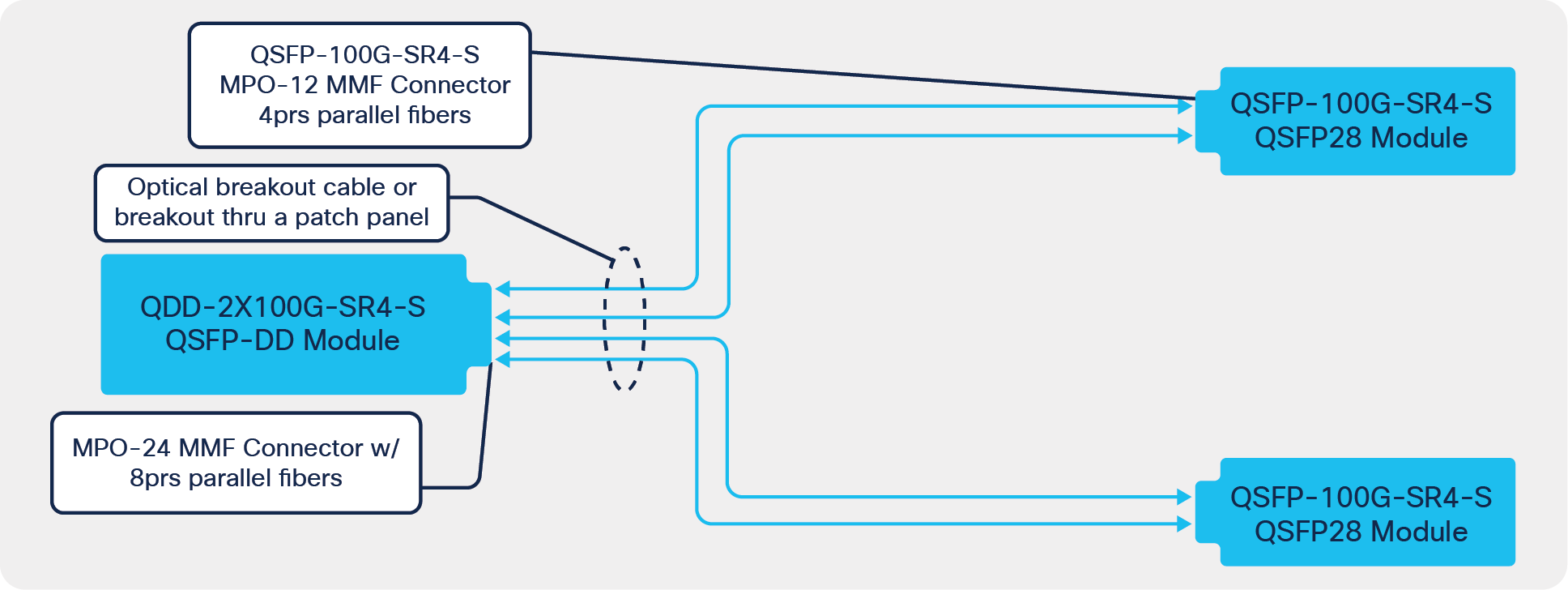
MPO-24 used for breakout on QDD-2x100G-SR4-S
The transmit and receive of the optical lanes of the MPO-24 interface occupy the positions depicted in the following figure when looking into the module receptacle with the connector keyway feature on top.
Pinout for QDD-2X100-SR4-S
For the QDD-2X100-LR4-S and QDD-2X100-CWDM4-S, the transceivers utilize 2x CS connectors for breakout. Each CS connector has a full duplex channel as shown in the following diagram.
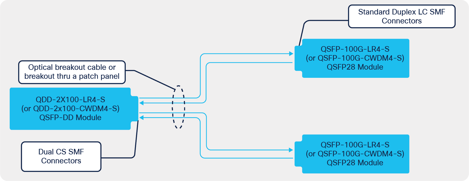
Dual CS connectors used for breakout on QDD-2X100-LR4-S and QDD-2X100-CWDM4-S
The advantage of the new CS connector (Figure 7) provides breakout capability at the transceiver (Figure 8) instead of requiring a breakout cable or breakout cartridge in a patch panel. Traditional assemblies use MPO connectors on one end and multiple LC duplex connectors at the other end.
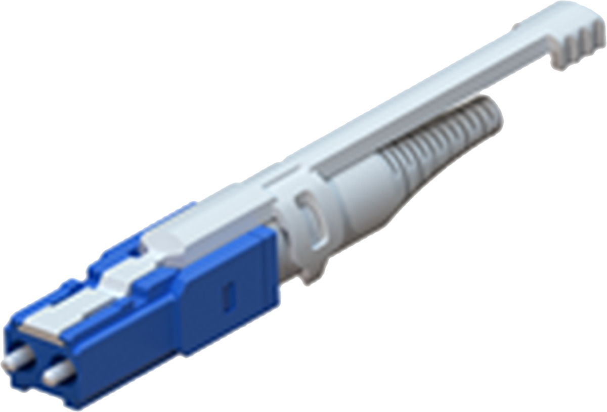
New CS connector
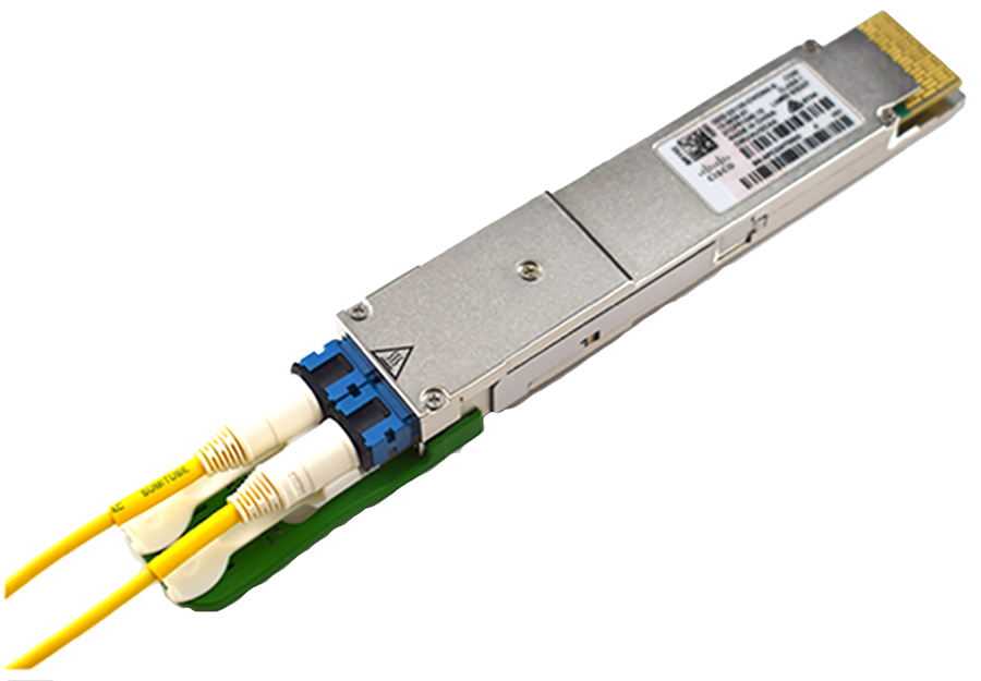
Module with 2x CS connector
The transmit and receive of the optical lanes of the dual CS interface occupy the positions depicted in the following figure when looking into the module receptacle with the connector keyway feature on top.
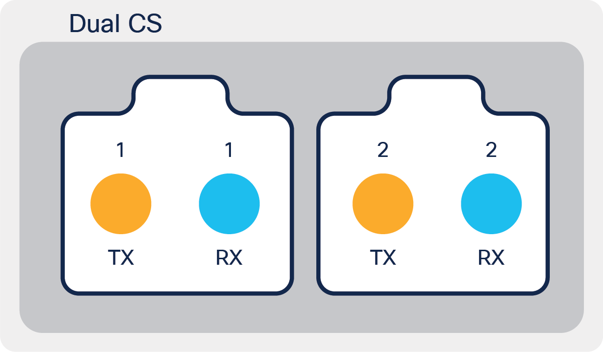
Pinout for QDD-2X100-LR4-S and QDD-2X100-CWDM4-S
For the QDD-400G-SR8, the transceiver utilizes the MPO-16 connector for breakout to 2x QSFP-100G-SR4-S modules as shown in the following diagram with breakout to 8x SFP-50G-SR.
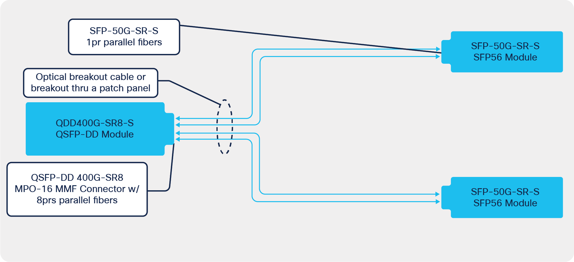
MPO-16 on QDD-400-SR8-S for breakout to SFP-50G-SR.
And alternate breakout to 2x QSFP-200G-SR4 is shown in the following figure.
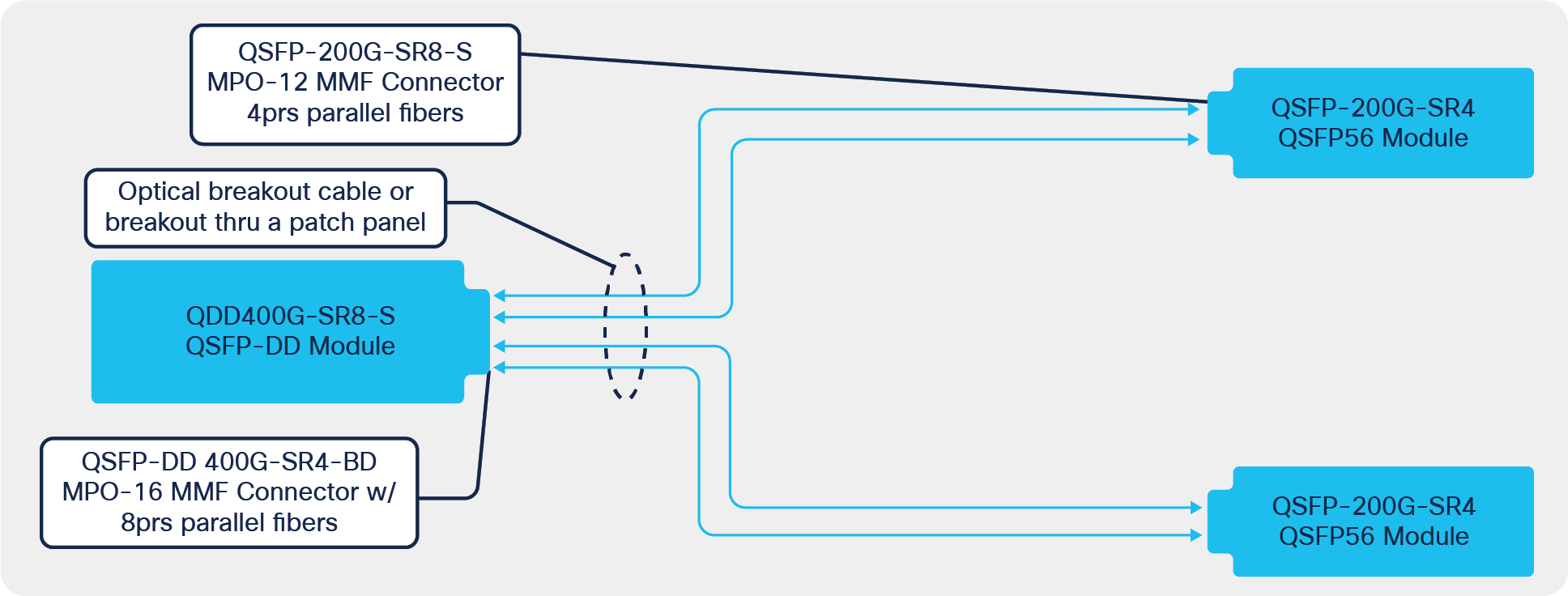
MPO-16 on QDD-400-SR8-S for breakout to 2x QSFP-200G-SR4
The transmit and receive of the optical lanes of the MPO-16 interface occupy the positions depicted in the following figure when looking into the module receptacle with the connector keyway feature on top.
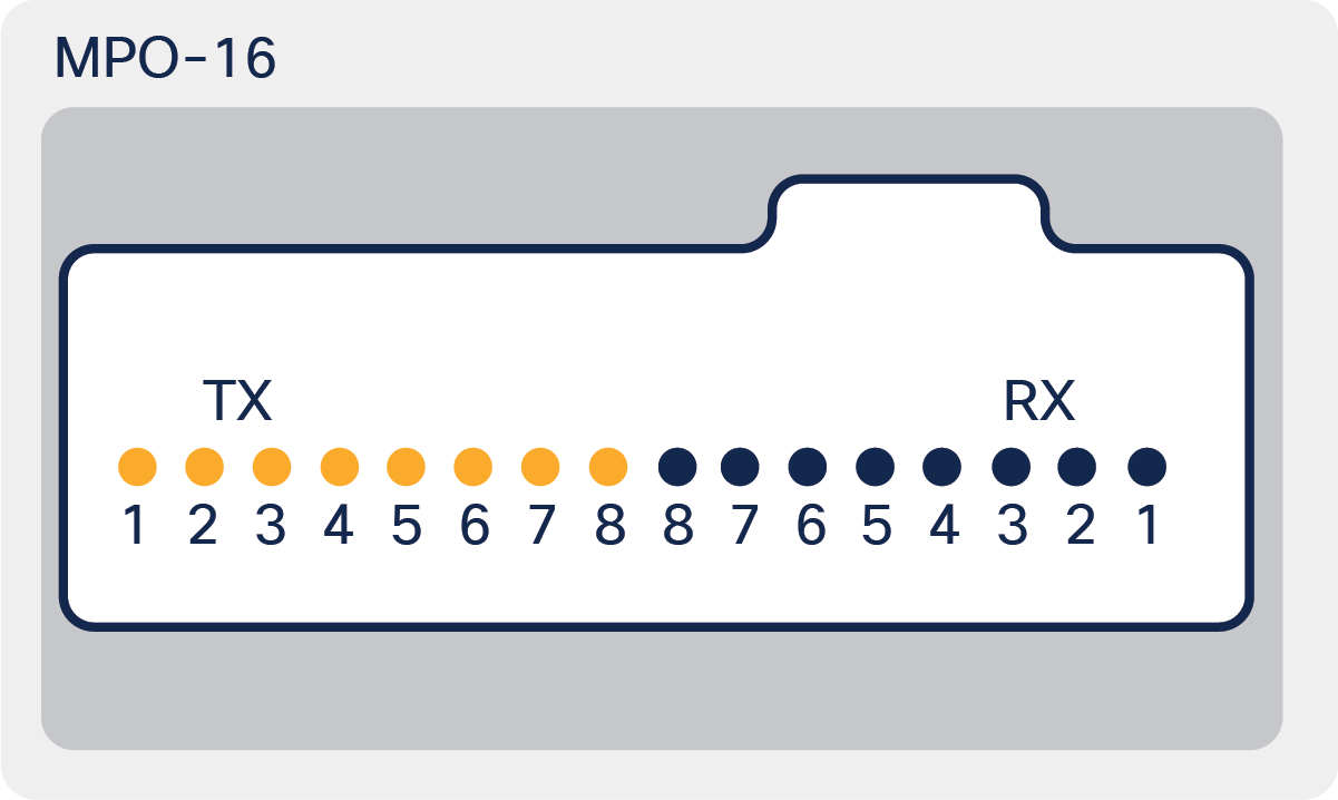
Pinout for QDD-400G-SR8
Important note:
Remember, fiber breakout patch cords or cartridges are for pluggable optic transceivers. If you’re using an AOC (Active Optical Cable) such as QSFP-4X10G-AOCxM or copper cables such as QSFP-4SFP25G-CUxM, the breakout structure may be built into the cable because they are pre-terminated and plug directly into the QSFP- or SFP-type ports. Therefore, these cables do not need a separate fiber breakout patch cord.
Comparing downlink density for switches with and without breakout capability
While breakout is not a new concept, it is becoming increasingly important as equipment manufacturers look to dramatically increase bandwidth and faceplate density while still having access to low-speed ports. For example, consider the advantages of a 1RU 19-inch fixed-port switch, which has a faceplate with 36x QSFP ports as shown in figure 17 that can be used as either uplinks or downlinks. The ports are generally QSFP+ (40G), QSFP28 (100G), or QDD (400G). Compare this with an example of a same-size switch that has 48x single-lane downlink ports, which cannot be broken out, and 6x QSFP uplink ports (see Figure 18). The data rates of the downlink ports would match the lanes of the QSFP ports. For example, 10G SFP+ for QSFP+, 25G SFP28 for QSFP28, and 50G SFP56 for QDD.
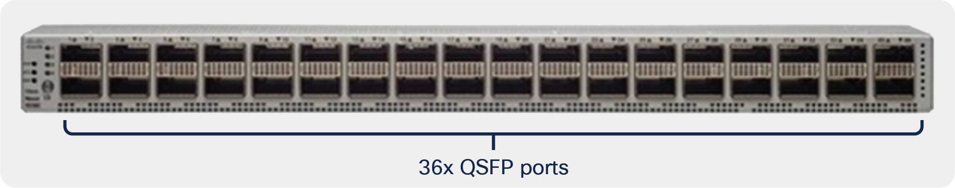
Switch that supports high-density QSFP downlinks with breakout
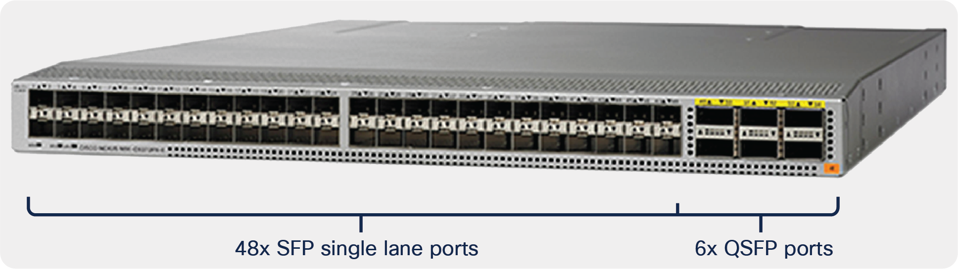
Switch with single-lane downlinks
The benefit of a QSFP-only switch over a switch with single-lane downlinks depends on the type of QSFP port and the 1:2 oversubscription ratio. For 40G configurations, the total capacity is 240 Gbps upstream and 480 Gbps downstream. For 100G configurations, the total capacity is 600 Gbps upstream and 1200 Gbps downstream.
Table 3 shows that the switches that support breakout in all ports provide twice the density of downlink ports as switches that have single-lane downlink ports.
Table 3. Single-lane downlink vs. a QSFP+ or QSFP28-only switch
| Switch type |
Uplink rate |
# Uplinks |
Downlink rate |
# Downlinks |
| Single-lane downlinks |
40G (QSFP+) |
6 |
10G |
48 |
| 100G (QSFP28) |
6 |
25G |
48 |
|
| QSFP-only (supports breakout) |
40G (QSFP+) |
12 |
10G |
96 |
| 100G (QSFP28) |
12 |
25G |
96 |
A data center example using Cisco switches:
● 96x servers (3 racks with 32 servers per rack)
● 25GbE per server
● 2:1 oversubscription
Would require:
● 2x Cisco Nexus 93180YC-FX3S Switch (48x 1/10/25G SFP and 6x 40/100G QSFP ports) with 96x direct connections
or
● 1x Cisco Nexus 9336C-FX2 Switch (36x 40/100G ports) with 96x connections using break out
Table 4 shows a similar comparison between 400G QSFP-DD switches. In this case, the switch that supports breakout in all ports provides triple the downlink port density of the single-lane type.
For 400G QDD (also known as QSFP56-DD) configurations the oversubscription changes to 1:1 with 2400 Gbps of both upstream and downstream capacity because QDD ports have 8 lanes and thus have 2x the capacity of QSFP+ or QSFP28 ports that have 4 lanes.
Table 4. Single-lane downlink vs. QSFP-DD-only switch
| Switch type |
Uplink rate |
# Uplinks |
Downlink rate |
# Downlinks |
| Single-lane downlinks |
400G (QDD) |
6 |
50G |
48 |
| QDD-only (supports breakout) |
400G (QDD) |
18 |
50G |
144 |
Breakout advantages and disadvantages
Advantages of breakout:
● Higher density. For example, a 36-port QDD breakout switch can provide triple the density of a switch with single-lane downlink ports. Thus achieving same number of connections using less number of switches.
● Access to lower-speed interfaces. For example, the QSFP-4X10G-LR-S transceiver enables a switch with only QSFP ports to connect 4x 10G LR interfaces per port.
● Economic Savings. Due to less need for common equipment including chassis, cards, power suppliers, fans, …
Disadvantages of breakout:
● More difficult replacement strategy. When one of the ports on a breakout transceiver, AOC or DAC, goes bad, it requires replacement of the whole transceiver or cable.
● Not as customizable. In switches with single-lane downlinks, each port is individually configured. For example, an individual port could be 10G, 25G, or 50G and could accept any type of transceiver, AOC or DAC. A QSFP-only port in breakout mode requires a group-wise approach, where all interfaces of a transceiver or cable are the same type.
Other considerations for breakout
Breakout and redundancy
Breakout enables redundant connectivity. Consider the example in Figure 9, which shows QSFP28 100G transceivers in switch and server ports, where the 4x25G lanes of each transceiver are broken out into 50G (2x25G) connections. The breakout capability provides redundant 50G connectivity between switches and servers.
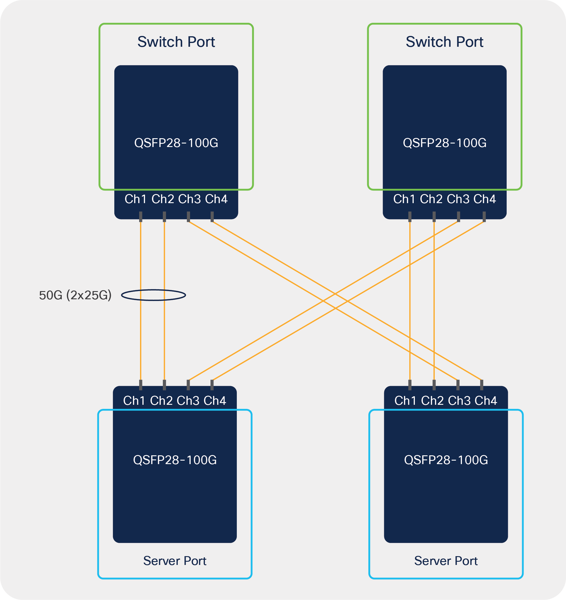
Breakout and redundancy
Breakout mode for communication applications is becoming more important as solutions demand increased density and lower cost, as well as other factors, such as interconnect and replacement strategies that need to be considered for the overall solution.
Cisco has a variety of breakout cables and transceivers. For more information see: www.cisco.com/go/optics.
For breakout capability of specific Cisco® transceivers, see the Cisco Optics-to-Optics Interoperability Matrix: https://tmgmatrix.cisco.com/iop.
The Cisco Optics-to-Device Compatibility Matrix is a great tool for determining if a transceiver supports breakout across a wide variety of Cisco platforms and software releases: https://tmgmatrix.cisco.com/.