Distributed Cloud Computing and its Impact on the Cabling Infrastructure within a Data Center White Paper
Available Languages
Bias-Free Language
The documentation set for this product strives to use bias-free language. For the purposes of this documentation set, bias-free is defined as language that does not imply discrimination based on age, disability, gender, racial identity, ethnic identity, sexual orientation, socioeconomic status, and intersectionality. Exceptions may be present in the documentation due to language that is hardcoded in the user interfaces of the product software, language used based on RFP documentation, or language that is used by a referenced third-party product. Learn more about how Cisco is using Inclusive Language.
Applications such as high-frequency trading, high-performance computing, AI, and gaming are compute intensive and latency sensitive. To process these workloads in the most optimized way, data center operators must move a significant portion of their computational load towards the edge of the network closer to the source of the data. This decentralizing of the cloud creates challenges for data center operators looking for ways to grow the computational power within their data center to meet the demands of these emerging applications. This paper will cover the various applications driving the shift towards edge computing, and how this impacts the cabling infrastructure in environments that are highly space constrained.
In a traditional cloud computing architecture, the compute and storage of all data is centralized. The cloud is able to leverage its massive compute and storage capability for large-scale data analysis and data storage. While the intelligence of the infrastructure continues to reside in the cloud, latency-sensitive data is processed using an edge computing model. Edge computing is a means of processing data physically close to where the data is being produced, which reduces latency and bandwidth use.
Maximizing compute power can be done by growing computational footprint, which would mean adding more racks in the data center with more compute, storage, and networking. This approach, however, may not be possible nor economically feasible in a co-location or smaller self-owned data center environment. An alternative option for data center operators is to leverage the existing footprint by building out higher density racks. These density-optimized racks impact the compute, storage, and, in particular, the network cabling infrastructure.
In an edge computing model as shown in Figure 1 below, functions such as compute, storage, and networking are moved closer to the source of the data.
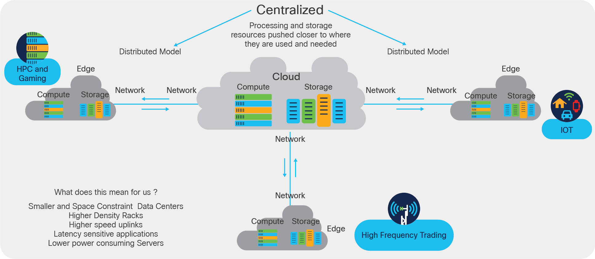
Transition from a centralized to a decentralized model for edge computing
The benefit of smaller data centers in a distributed model as shown in Figure 1 above is that cloud providers can deliver content to the end user at much faster rates due to their proximity to the source or the user.
Let’s look at some of the applications that benefit the most from using an edge computing model. Applications such as High-Performance Computing (HPC), cloud gaming, and High-Frequency Trading (HFT) all have low latency requirements and are compute intensive.
With high-frequency trading, millions of orders need to be executed in a matter of seconds. Financial institutions find it necessary to either buy real estate as close as possible to the exchange in trading offices or follow a co-location model by leasing space within a service provider’s data center. The co-location services offered by financial institutions minimize network and other latencies.
With co-location or smaller data center buildouts, space is limited, which forces power-hungry racks to become denser. High-frequency trading requires per core performance, high bandwidth/throughput, and low latency. To design a data center optimized for high-frequency trading, there is a need to build high-density racks. Data center designs will shift towards density-optimized servers with a higher number of I/O connections, higher density top-of-rack switches with downstream ports of 100 Gigabit Ethernet and above, and a connectivity infrastructure making use of pluggable transceivers or preassembled active optical cables.
With cloud gaming, much of the success depends on delivering services to end users with very little latency or lag, resulting in another growing use case for edge computing. The gaming companies that provide the fastest infrastructure will be the most successful. A reduction in 20 to 30 µs may differentiate a successful gaming company from its competitors. To deliver with low latency and lag, a gaming company needs to either own or rent space from an existing data center in a co-location model. Owning their own data centers can be costly and difficult to manage, so most gaming companies will opt for a co-location model.
Because these gaming companies lease space, it’s to their advantage to build out density-optimized racks to support gaming servers equipped with powerful Graphical Processor Units (GPUs).
High-performance computing is suited for scientific-based applications, including biological sciences, geosciences, weather forecasting, engineering, simulation, design, defense, and security. High-performance computing requires high network throughput while maintaining low latency.
In all three cases, with processing of data moved to the edge, the common factors are space constraints, a need for a greater number of I/O connections, and higher I/O Speeds. With these smaller data centers, operators do not have the luxury of deploying a massive number of racks and have to maximize computational power within a rack.
Packing more computing power into a smaller space:
Today, in a standard 19-inch rack, a typical design may include up to 32 servers per rack, with I/O connectivity at 1G or 10G originating from the network interface card, connecting upstream to the top-of-rack switch as seen in Figure 2 below:
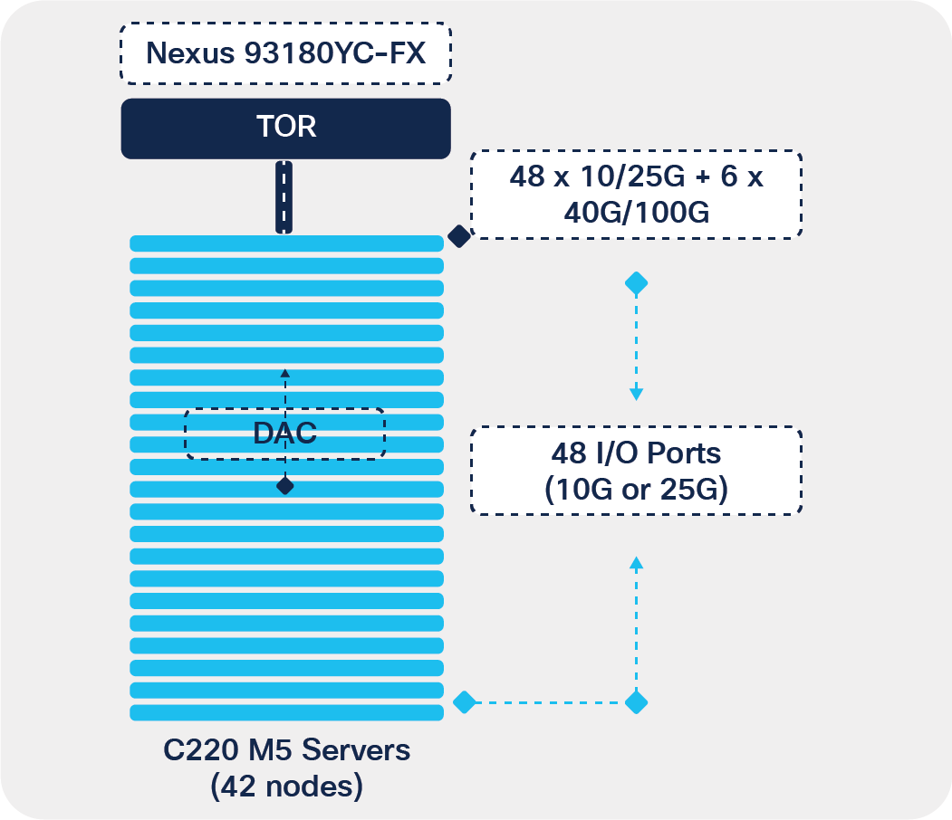
Server connectivity using 1 RU rack servers
The example in Figure 2 above shows an existing rack with Cisco’s C220 M5 server connecting upstream at 10G or 25G speed to a Nexus 93180YC-FX top-of-rack switch. This example assumes a 2:1 oversubscription model with 48 x 25G ports, or a nonblocking model with 48 x 10G ports originating from the top-of-rack switch.
To handle heavier and latency-sensitive workloads and computing tasks, one approach is to pack more computing power into a smaller space. These density-optimized data centers reduce costs in terms of physical infrastructure because the data center maybe located in a smaller space. These density-optimized designs also simplify operations due to having a smaller number of racks to manage.
The first step to increase computational power is to increase the number of servers within a rack. This can be done through the use of high-density rack servers.
Today, vendors, including Cisco, offer a high-density 2RU rack server chassis, which doubles the number of compute nodes within a RU, while also supporting double the number of I/O connections to the top-of-rack switch, at higher speeds.
The Cisco® UCS C4200 Series Rack Server Chassis is a modular, dense rack server chassis that supports a minimum of two and a maximum four UCS C125 M5 Rack Server Nodes and is optimized for use in environments requiring dense compute form factor.
The use of dense rack servers increases the number of compute nodes and doubles the number of I/O connections within a rack as shown in Table 1 below:
Table 1. Server connectivity comparison table
| UCS C4200 (C125) |
UCS C220 |
|
| Max servers per rack |
84 |
42 |
| Servers per RU |
2 |
1 |
| Max I/O per rack |
168 |
84 |
With the increase in the number of I/O connections within a rack, the top-of-rack switch will also need to evolve. By upgrading the top-of-rack switch to support 100G ports facing downstream to the servers, data center operators can now break out the 100G ports to 4 x 25G and thus grow the number of I/O connections to 128.
The example in Figure 3 below shows an evolution from a Cisco UCS C220 M5 server connecting upstream at 10G speed to a high-density UCS C4200 modular rack server connecting upstream to a Nexus 9336C-FX2 top-of-rack switch with double the number of I/O connections.
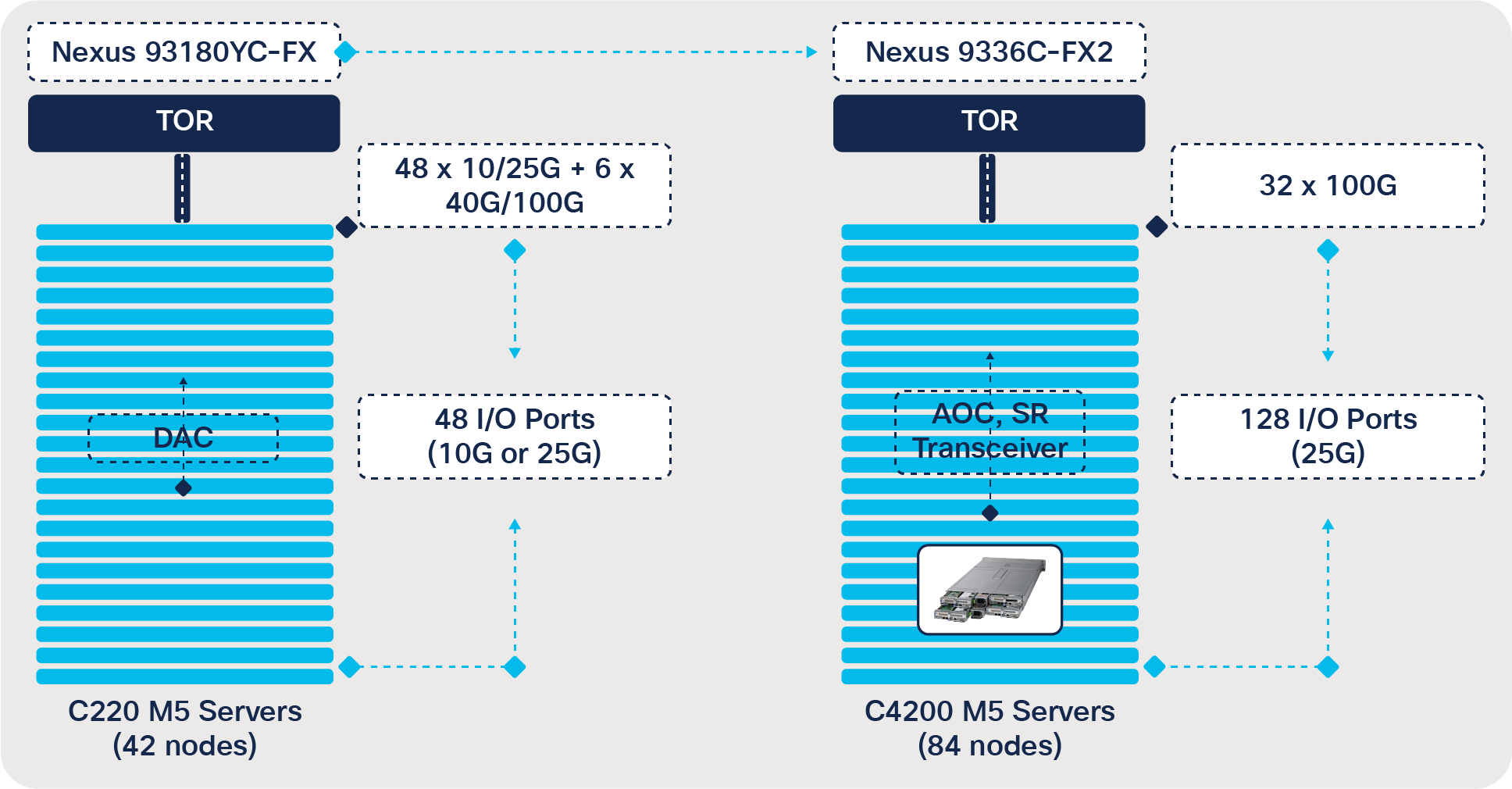
Rack density optimization using multimode chassis
To address the higher connectivity requirements, one option is to use 4x25G breakout cables originating from the top-of-rack switch with 100G ports, terminating at 25-Gbps speeds downstream. Today Cisco offers 100 Gigabit Ethernet to four 25 Gigabit Ethernet direct-attach copper breakout cables suitable for very short links and offers a cost-effective way to connect within racks and across adjacent racks. These breakout cables connect to a 100G QSFP28 port of a Cisco switch on one end and to four 25G SFP28 ports of a Cisco server on the other end.
An alternative option would be to use pluggable QSFP-100G-SR4-S optics with the top-of-rack switch and use breakout cables to connect downstream to servers at 25G speeds, using 25G optics, Cisco SFP-25G-SR-S, or Cisco SFP-10/25G-CSR-S if the reach requirement exceeds 100 m.
Pluggable modules are transceivers that plug into switches, routers, and server ports. Some of the common form factors for these pluggable optics used in a data center include:
● SFP (Small Form-factor Pluggable): 1 Gigabit Ethernet speed, typically an LC fiber connector
● SFP+ (Small Form-factor Pluggable Plus): 10 Gigabit Ethernet speed, typically LC fiber connector
● QSFP (Quad Small Form-factor Pluggable): 40 and 100 Gigabit Ethernet, MPO
● QSFP-DD (Quad Small Form-factor Pluggable – Double Density): 200 and 400 Gigabit Ethernet, MPO or LC
The decision to deploy copper/AOC preassembled cables versus pluggable optics is driven by cost and manageability factors, as well as investment protection in any future upgrades. In a greenfield deployment, assuming cost is the only factor, most data center operators will opt for copper (DAC), particularly if the connectivity between the top-of-rack switch and the servers remains within a rack.
As the density requirement grows within the rack, there is a question as to whether copper cable is a viable solution versus a pluggable transceiver. As the density grows, the weight of the copper cable becomes a significant factor. This is particularly true with longer cables as they may contribute to increased failure rates due to the increased weight and stress on the switch ports. Copper cables can take up a significant amount of space and reduce the flow of air, which could cause overheating of equipment resulting in failure of the hardware. To reduce the stress and bulkiness of copper, data center operators can use Active Optical Cables (AOCs) or use pluggable transceivers.
Another decision factor when considering cables versus transceivers is the operational challenge of troubleshooting and replacing cables, particularly at longer reaches. Swapping out cable traversing multiple racks is costly and time-consuming. The use of transceivers offers a field-replaceable option for the endpoints. So, while the initial cost of pluggable transceivers is higher, in the event of a connectivity failure, operators can simply swap out one or both of the end points without having to swap out the connecting cable. This is a significant operational expenditure reduction.
One last critical factor is the investment protection while upgrading infrastructure. Installing a cabling fiber plant is costly and disruptive to data center operations and may require downtime. With pluggable transceivers, data center operators can simply swap out the 10-Gbps transceivers and upgrade to 25 Gbps, leveraging their existing infrastructure. With copper or AOC, an upgrade in speed would require swapping out the entire cable, so while the initial investment using copper or AOC is advantageous compared to a pluggable transceiver, when having to do bandwidth upgrade, that advantage is lost.
Cisco offers the following pluggable transceivers for a 100G to 25G breakout use case:
Table 2. Cisco pluggable transceiver for 10/25/100 Gbps
| SKU |
Description |
| QSFP-100G-SR4-S |
Cisco 100GBase SR4 QSFP Transceiver, MPO, 100 m over OM4 MM5 |
| SFP-25G-SR-S |
Cisco 25GBase-SR SFP Transceiver, 100 m over OM4 MM5 |
| SFP-10/25G-CSR-S |
Cisco 10/25GBase-CSR SFP28 Transceiver, 400 m over OM4 MM5 |
This paper, up to this point, has focused on the logical layouts of the servers, switches, and connectivity utilized by applications such as, high-performance computing, cloud gaming, and high-frequency trading. The remainder of the paper is going to focus on the physical infrastructure layout and products needed to enable these applications. Panduit offers a complete solution for the infrastructure supporting Cisco switches, servers, and other devices.
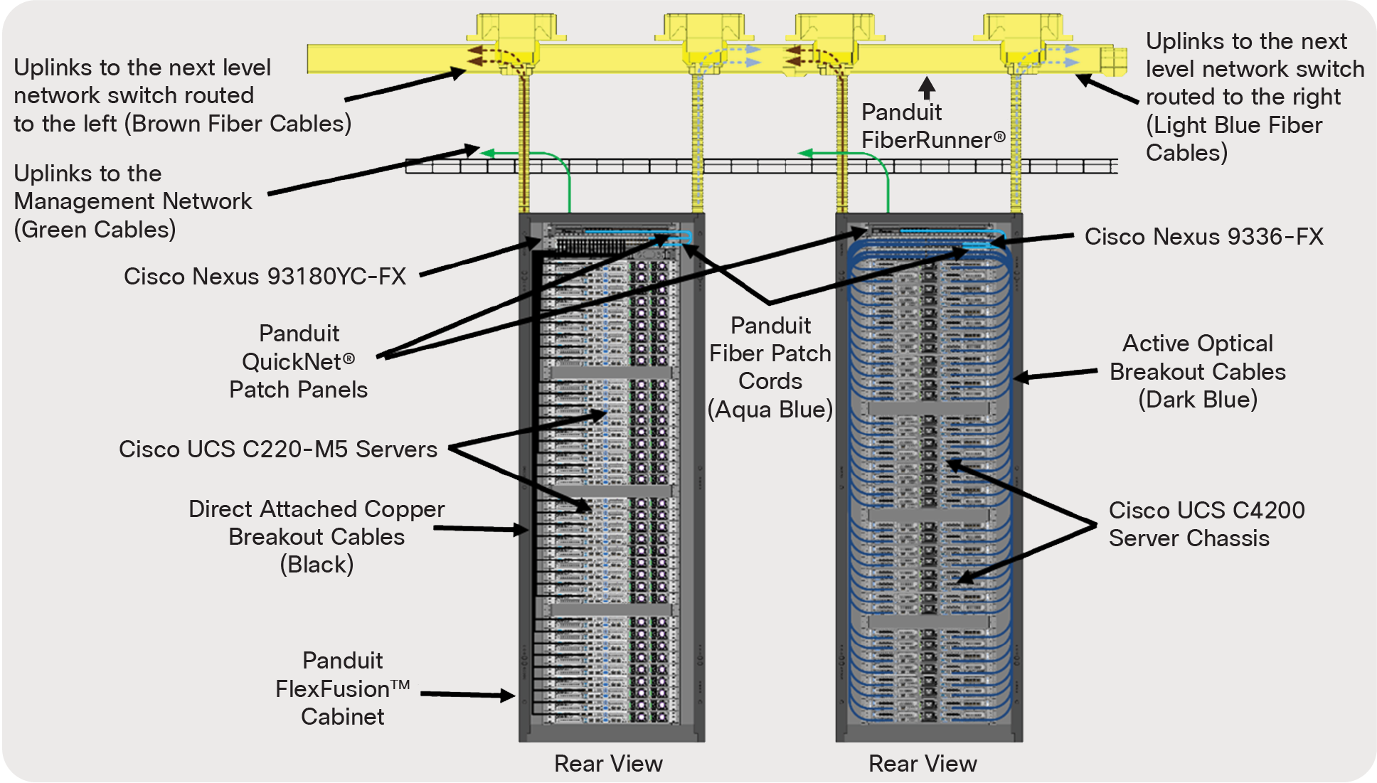
Space constraint rack
The image above (Figure 4) is displaying two different forms of connectivity between server and switch, as well as transceiver and fiber connectivity from access/leaf switch to the next level network switch.
In the cabinet on the left side of the image, a Cisco UCS C220-M5 server is connecting to a Cisco Nexus 93180YC-FX switch via a Direct Attached Copper (DAC) breakout cable. These cables are connecting utilizing 100G ports on the switch breaking out to (4) 25G ports on the servers utilizing copper twinax cable. Both Cisco and Panduit provide DAC breakout cables. The part numbers are listed in the tables below.
In the cabinet on the right side of the image, a Cisco UCS C4200 chassis server is connecting to a Cisco Nexus 9336-FX switch via an Active Optical Cable (AOC) breakout cable. These cables are connecting utilizing 100G ports on the switch breaking out to (4) 25G ports on the servers utilizing fiber connectivity with transceivers preinstalled on both ends of the cable. Panduit provides AOC breakout cables in various lengths up to 30 meters. The part numbers are listed in the tables below.
Both cabinets are utilizing QSFP-100G-SR4-S transceivers and PanMPO™ OM4 12 fiber patch cords and trunks for the uplinks from the switches to the next-level network switch.
A description of key components to connect and manage the network infrastructure are listed below:
● QuickNet™ PanMPO™ patch cords and trunks: Small in diameter, extremely flexible and intended for shorter cable runs. These cables use PanMPO Fiber Connectors, a patented MPO design that can be reconfigured for gender and polarity in the field.
● QuickNet Patch Panels: High-density patch panels conserve rack space with 96 fibers (48 duplex ports) per RU. Available in flat or angled patch panels for proper bend radius control and to minimize the need for horizontal cable managers.
● FiberRunner® Routing System: A simple-to-install-and-configure system of channels, fittings, and brackets designed to segregate, route, and protect fiber optic and high-performance copper cabling.
Cisco part numbers:
Table 3. Cisco Nexus Switch part numbers
| Switch |
Description |
| Cisco Nexus 93180YC-FX |
48 x 1/10/25-Gbps SFP/SFP28 ports and 6 x 40/100-Gbps QSFP28 ports |
| Cisco Nexus 9336C-FX2 |
36 x 40/100-Gbps QSFP28 ports |
Table 4. Cisco UCS Server part numbers
| Server |
Description |
| UCSC-C220-M5SX |
UCS C220 M5 SFF 10 HD w/o CPU, mem, HD, PCIe, PSU |
| UCSC-C220-M5SN |
UCS C220 M5 SFF 10 NVMe w/o CPU, mem, HD, PCIe, PSU |
| UCSC-C4200-SFF |
UCS C4200 Rack Server Chassis, one rail kit, and bezel |
| UCSC-C125 |
UCS C125 M5 Rack Server Node based on AMD EPYC CPUs |
Table 5. Cisco network interface card part numbers
| Network Interface Card |
Description |
| UCSC-PCIE-C25Q-04 |
Cisco VIC 1455 VIC PCIE – Quad-Port 10/25G SFP28 |
| UCSC-MLOM-C25Q-04 |
Cisco UCS VIC 1457 Quad-Port 25G SFP28 mLOM |
| UCSC-PCIE-ID10GF |
Intel X710-DA2 Dual-Port 10Gb SFP+ NIC |
| UCSC-PCIE-IQ10GF |
Intel X710 Quad-Port 10Gb SFP+ NIC |
| Cisco UCSC-PCIE-QD25GF |
Qlogic QL41212H Dual-Port 25Gb NIC |
| UCSC-PCIE-ID25GF |
Intel XXV710 Dual-Port 25Gb SFP28 NIC |
| UCSC-P-M4D25GF |
Mellanox MCX4121A-ACAT Dual-Port 10/25G SFP28 NIC |
| UCSC-P-M5D25GF |
Mellanox CX-5 EN MCX512A-ACAT 2x25/10GbE SFP PCIe NIC |
Table 6. Cisco 100G copper breakout cable part numbers
| 100G Copper Breakout Cables |
Description |
| QSFP-4SFP25G-CU1M |
Cisco 100GBase QSFP to 4xSFP25G Passive Copper Splitter Cable, 1m |
| QSFP-4SFP25G-CU2M |
Cisco 100GBase QSFP to 4xSFP25G Passive Copper Splitter Cable, 2m |
| QSFP-4SFP25G-CU3M |
Cisco 100GBase QSFP to 4xSFP25G Passive Copper Splitter Cable, 3m |
| QSFP-4SFP25G-CU5M |
Cisco 100GBase QSFP to 4xSFP25G Passive Copper Splitter Cable, 5m |
Table 7. Cisco Pluggable Transceiver part numbers
| Pluggable Transceivers |
Description |
| QSFP-100G-SR4-S |
Cisco 100GBase SR4 QSFP Transceiver, MPO, 100m over OM4 MM5 |
| SFP-25G-SR-S |
Cisco 25GBase-SR SFP Transceiver, 100m over OM4 MM5 |
| SFP-10/25G-CSR-S |
Cisco 10/25GBase-CSR SFP28 Transceiver, 400m over OM4 MM5 |
Panduit
Table 8. Panduit Cable, Cabinet and Fiber Connectivity part numbers
| Product |
Description |
| Direct Attached Copper Breakouts 100G to (4) 25G |
|
| PHQ4SFP2A1MBL |
QSFP28 to SFP28 Breakout Copper Cable Assembly, 30 AWG, Black, 1m |
| PHQ4SFP2A2MBL |
QSFP28 to SFP28 Breakout Copper Cable Assembly, 30 AWG, Black, 2m |
| PHQ4SFP2A3MBL |
QSFP28 to SFP28 Breakout Copper Cable Assembly, 30 AWG, Black, 3m |
| PHQ4SFP2C4MBL |
QSFP28 to SFP28 Breakout Copper Cable Assembly, 26 AWG, Black, 4m |
| PHQ4SFP2C5MBL |
QSFP28 to SFP28 Breakout Copper Cable Assembly, 26 AWG, Black, 5m |
| Active Optical Cable Breakouts 100G to (4) 25G |
|
| AZ83NQ2S2AQM001 |
Active Optical Cable Assembly, QSFP28 to SFP28, 100-4x25G, OM4, Aqua, 1m |
| AZ83NQ2S2AQM002 |
Active Optical Cable Assembly, QSFP28 to SFP28, 100-4x25G, OM4, Aqua, 2m |
| AZ83NQ2S2AQM003 |
Active Optical Cable Assembly, QSFP28 to SFP28, 100-4x25G, OM4, Aqua, 3m |
| AZ83NQ2S2AQM005 |
Active Optical Cable Assembly, QSFP28 to SFP28, 100-4x25G, OM4, Aqua, 5m |
| AZ83NQ2S2AQM007 |
Active Optical Cable Assembly, QSFP28 to SFP28, 100-4x25G, OM4, Aqua, 7m |
| Cabinet and Fiber Connectivity |
|
| QPP24BL |
QuickNet 24-port Patch Panel |
| FZTRP7N7NYNF003 |
OM4 12 fiber PanMPO Interconnect, Female to Female, Method B, 3ft |
| FQMAP66CG |
Fiber Optic Migration Adapter Panel - 6 MPO Adapters – Type B |
| QPPBBL |
QuickNet Slot Blanking Panel |
| XG74222BS0001 |
Panduit FlexFusion Cabinet 700mm 42RU 1200mm deep |
| CMPH1 |
Panduit Cable Manager 1 RU |
| TLBP1S-V |
Tool-less Blanking Panel 1 RU |
In summary, edge computing is changing the way data center infrastructure is built and managed. High-frequency trading, cloud gaming, and other compute-intensive applications are driving the need for density-optimized data centers located remotely, close to the edge to reduce latency and lag. This shift from a centralized to a distributed model brings with it a whole set of new requirements when populating racks with compute, storage, and networking infrastructure. Evolution to high-density rack servers, higher speed top-of-rack switches, and space-optimized cabling infrastructure that is manageable and scalable enables data center operators to deliver a reliable, secure, and overall improved end-user experience.
For more information on which optics and cables to use with switches and server network interface cards, visit:
Cisco Optics-to-Device Compatibility Matrix:
https://tmgmatrix.cisco.com/
Cisco Optics-to-Optics Interoperability Matrix:
https://tmgmatrix.cisco.com/iop
Alliance landing USE VANITY URL:
https://panduit.com/