Single-Lambda 100G Pluggable Optics Solution Overview
Available Languages
Bias-Free Language
The documentation set for this product strives to use bias-free language. For the purposes of this documentation set, bias-free is defined as language that does not imply discrimination based on age, disability, gender, racial identity, ethnic identity, sexual orientation, socioeconomic status, and intersectionality. Exceptions may be present in the documentation due to language that is hardcoded in the user interfaces of the product software, language used based on RFP documentation, or language that is used by a referenced third-party product. Learn more about how Cisco is using Inclusive Language.
When it comes to network deployment strategies, you may be accustomed to treating pluggable optics as an afterthought. But over the past several years, higher data rate pluggable optics have been developed, and with that comes increased complexity in their design and their interactions with switch and router hosts. With today’s 100G optics, we’re at the point where it now influences your network hardware cost and fiber infrastructure design.
Cisco’s vision is to simplify 100G pluggable optics. With fewer components in the pluggable module, we can scale manufacturing volume and cost to the level of today’s 10G SFP+ optics. Through silicon photonics and signal processing technology, Cisco has taken the first step toward that vision: single-lambda 100G optics. When new-generation form factors are available, you’ll be able to reuse the first generation and transition gradually. It will also allow you to upgrade to 400G host platforms one site at a time. As a network operator, you can count on Cisco to focus on optics solutions that provide real-world benefits such as these.
● Future-proof your investment as 100G pluggable optics transition to new 100G form factors.
● Connect to 400G switches and routers without sacrificing port bandwidth.
● Upgrade to 400G switches and routers one site at a time.
Time for a new generation of 100G optics
Back when 10G SFP+ pluggable optical modules were state of the art, choices were few and simple. Furthermore, the modules themselves were straightforward in that their sole function was to convert electrical signals into optical signals, and vice versa.
In the years that followed, network bandwidth demands increased, which meant that the data rate of optical links also had to increase. And it not only increased - it accelerated. Standards bodies such as the IEEE and SFF had to consider ways to increase data rates that went beyond faster lasers and photo receivers. Techniques such as WDM (wavelength division multiplexing), parallel fiber, CTLE (continuous time linear equalization), and FEC (forward error correction) were built into standards.
Such complexity has consequences not only in the cost of the pluggable optical modules themselves, but also in fiber infrastructure design, which has implications in both hardware cost and operational cost. Complexity also increases the risk of failed interoperability between the pluggable optic and the switch or router, and between pluggable optics from different vendors. The bottom line is that for tomorrow’s 100G optics to be as low cost and low risk as today’s 10G SFP+ optics, a fundamental change is needed.
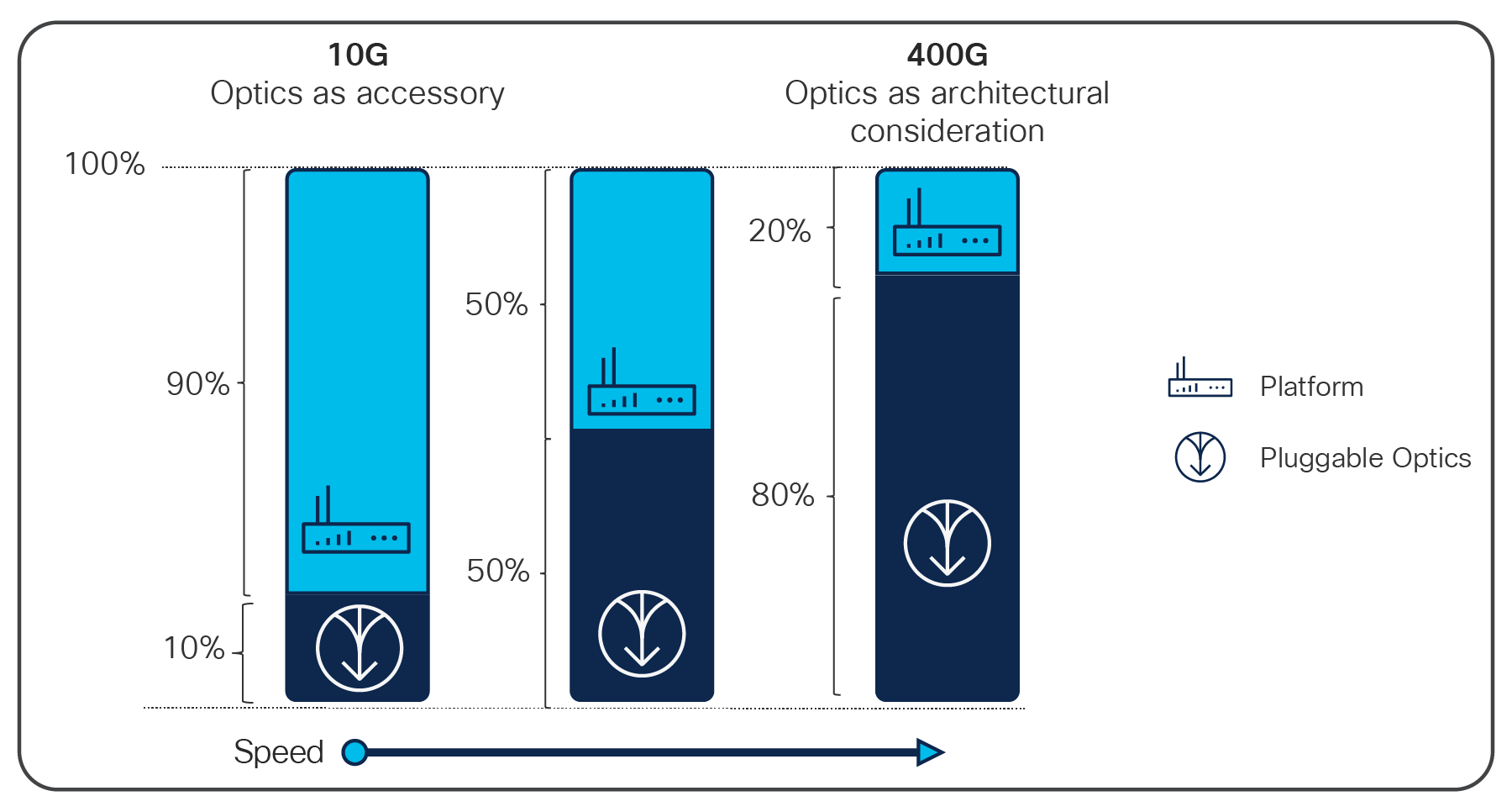
At 100G and 400G data rates, optics consume a more significant portion of the total system cost
The single-lambda 100G optical specifications were first standardized by the 100G Lambda MSA (multisource agreement). Led by Cisco Optics experts, this MSA quickly gained broad industry support due to its vision to create cost-effective solutions for high-density multi-terabit switching, routing, and transport networks. The goal was to define optical specifications that allow for future 100G and 400G pluggable optics that can be scaled to high-volume manufacturing, and therefore achieve low cost.
The basis of the single-lambda approach is the use of PAM4 (four-level pulse amplitude modulation). Prior to this, nearly all 100G optical specifications incorporated NRZ (non-return to zero), which is a two-level binary modulation format. PAM4, however, contains twice the amount of data without requiring significant increase in the speed of the optical components. Therefore, the same fundamental optical technology that can carry only 50G with NRZ can be used for 100G PAM4.
Manufacturability at high volume
Why is it important to minimize the components in the module? Consider the diagram in Figure 2. It shows what goes into today’s 100G QSFP28 pluggable optical modules. Notice that they are inherently four-channel devices, both in the optical interface facing right, and the electrical interface facing left. Each of the four channels carries 25G of NRZ data, for a total of 100G.
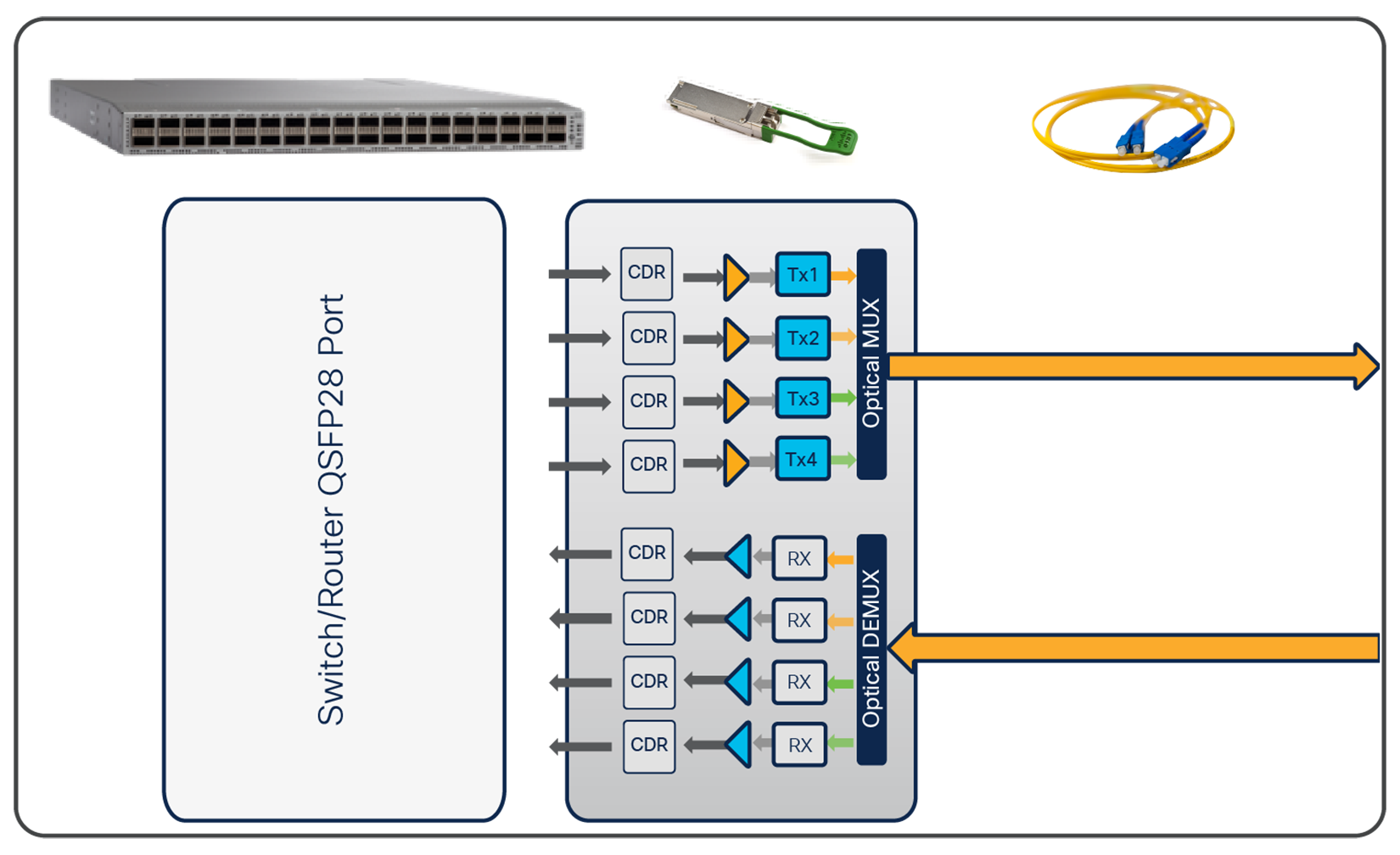
QSFP28 modules are inherently four-lane devices
Compare this with the diagram in Figure 3, a typical 10G SFP+ transceiver. It’s pretty simple. There is only one lane that carries 10G of data. There is typically only a laser, a photodiode, and simple driver circuits for optical-to-electrical and electrical-to-optical conversion. This simplicity is key to why manufacturers are able to make 20 million 10G SFP+ modules per year.
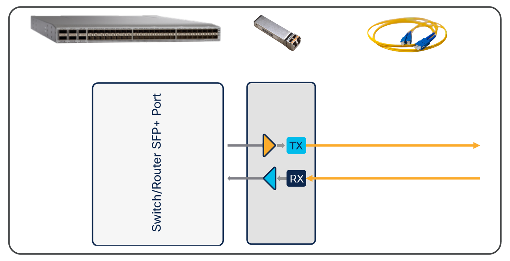
SFP+ modules are inherently single-lane devices
When 100G SerDes (serializer – deserializer) is available on switch and router ports, the ASIC behind the ports can take over the FEC and PAM4 functionality, leaving the pluggable module to perform only the optical-to-electrical and electrical-to-optical conversion. Then we could increase faceplate bandwidth density by using the smaller SFP form factor, with a single 100G lane on the electrical side that interfaces with the switch or router port. This form factor will likely be called SFP112.
In the meantime, QSFP28 modules perform the FEC and PAM4 inside the module, as well as convert the electrical 4x25G lanes to the single 100G lane. The benefit of adopting this QSFP28 now is that when the SFP112 becomes available, legacy switches and routers using QSFP28 modules will interoperate with the new hosts with SFP112 modules. And there won’t be any need for 4x25G-to-100G conversion because both the electrical interface and the optical signal will be single-lane 100G. This forward compatibility is highly advantageous for network upgrade strategies, as it prevents your existing QSFP28 modules from becoming obsolete as you add new SFP112-based hardware.
A diagram of an SFP112 module is shown in Figure 4. Note that it looks nearly identical to Figure 3. Both are single lane and need only a single laser and photo receiver. SFP112 will likely need CDR’s (clock and data recovery) circuits.
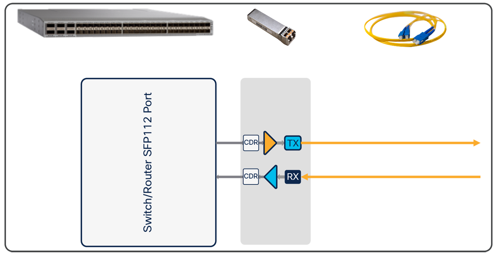
In the future, there will be an inherently 100G SFP form factor
Looking ahead to the latest generation of switches and routers with 400G ports, single-lambda 100G is essential for upgrading networks with operational flexibility. It enables QSFP-DD 400G pluggable optics that can interoperate with single-lambda 100G optics via fiber optic breakouts. For example, 400GBASE-DR4 modules, such as Cisco’s QDD-400G-DR4-S, can connect with four separate 100G FR modules, such as Cisco® QSFP-100G-FR-S. (see Figure 5)
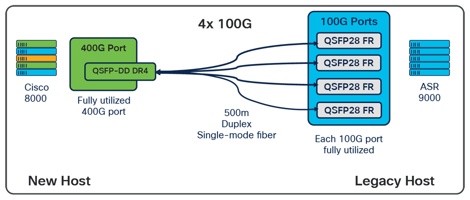
400G-to-100G connectivity via fiber breakout
This means that if you operate a network using gear with 100G QSFP28 ports, you can upgrade just one site to 400G gear, and still connect it to the existing 100G sites without sacrificing port bandwidth. This minimizes your downtime. And later you can upgrade the other sites when ready.
Cisco’s QSFP100 FR, DR, and LR optics
Cisco single-lambda 100G optics include the 100G FR, the 100G DR, the 100G LR, and the 100G ER-Lite. The 100G DR complies with the IEEE standard 100GBASE-DR, which has a reach of 500m and is ideal for applications inside data centers such as leaf-spine connectivity, where the fiber length seldom exceeds 100m. The 100G-FR complies with the 100G Lambda MSA’s 100G-FR specification, which has a reach of 2 km over duplex SMF and uses duplex LC connectors It is ideal for data center and co-location facility links and provides an alternative to CWDM4 optics across the same fiber and reach. The 100G LR expands the reach to 10km, enabling connections between buildings, data centers, and transport networks. It provides a forward compatible alternative to 100G LR4 10km links, and is ideal for connections in core and aggregation networks. The 100G ER-Lite complies with the Single-Lambda 100G MSA specification LR1-20 for 20km reaches, but can support links up to 25km when the Cisco 100G ER-Lite optic is used at both ends of the link. The extended reach is a result of the silicon photonics modulater in the Cisco optics which generates a clean signal that results in less distortion over longer distances. The Cisco ER-Lite optic provides a forward compatible alternative to the 40km ER4-Lite optic when only 25km reaches are required.
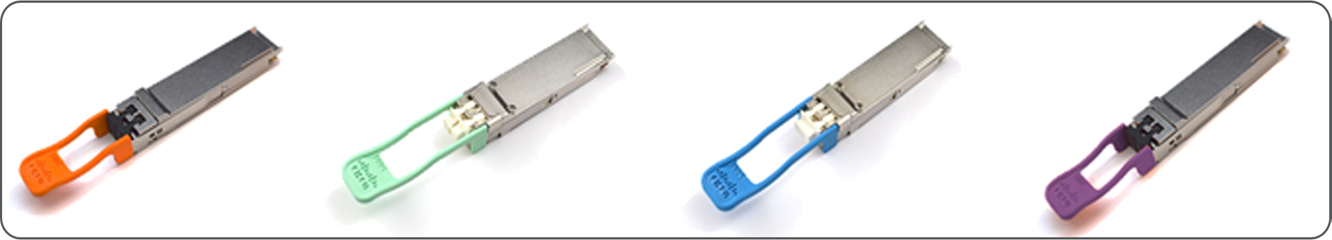
QSFP28 single-lambda 100G pluggable optics from Cisco
(Product ID QSFP-100G-DR-S, QSFP-100G-FR-S, QSFP-100G-LR-S, and QSFP-100G-ERL-S)
| Architecture |
Capabilities |
| Data Center |
● Leaf-spine connections
● High-radix architectures
● Connectivity to 400G and 800G ports
● Large server-to-server traffic
● Virtualized servers and LANs
● Two-hop server-to-server connectivity (
see Figure 7)
|
| Service Provider Networks |
● Incremental upgrade to 400G hardware
● Maximum use of 400G port bandwidth
● Future-proof QSFP28 hardware (
see Figure 8)
|
| Enterprise Campus Networks |
● Low-cost alternative to four-wavelength optics
● Short- and long-reach fiber links
● Core switch to aggregation switch connectivity
|
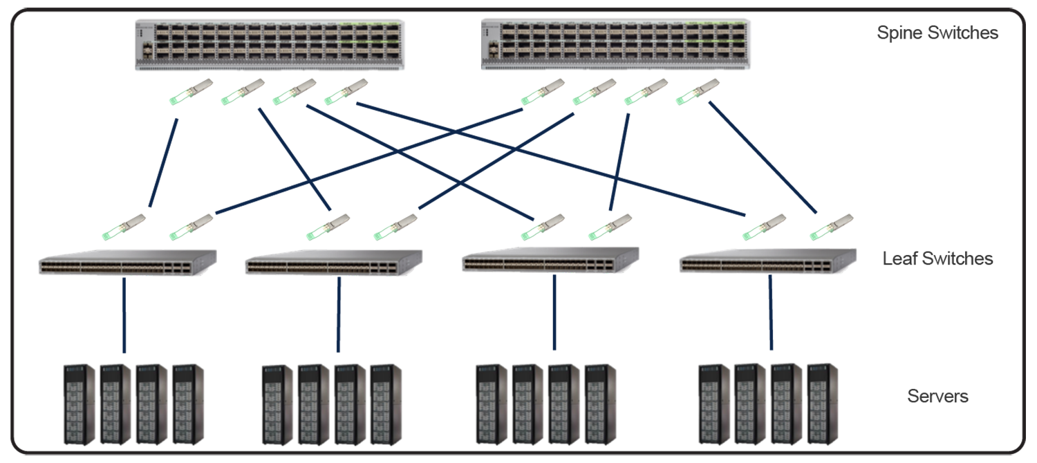
The QSFP28 DR module fits well in the data center in the connections between spine and leaf layers
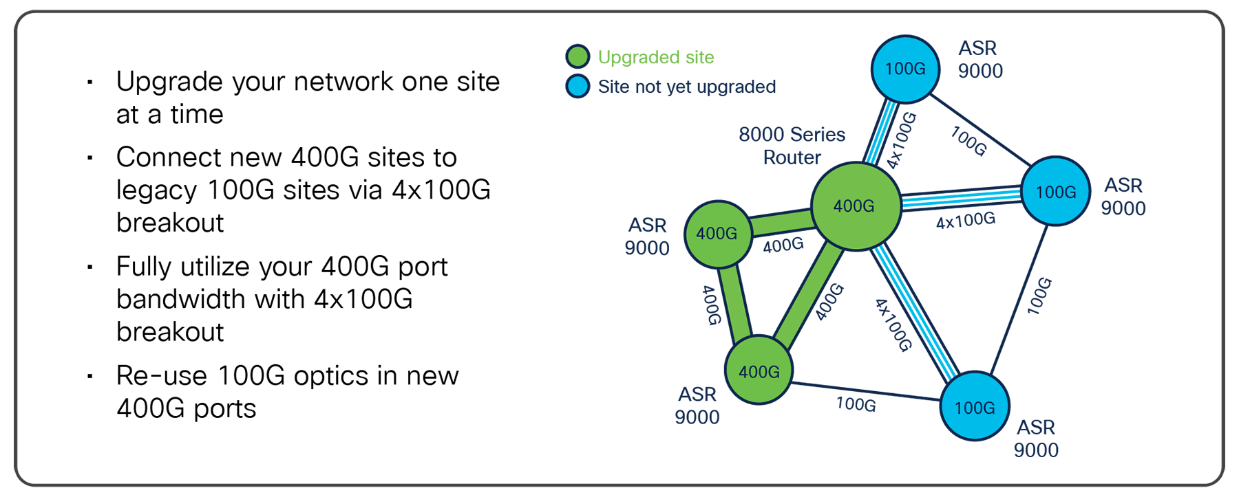
Single-lambda 100G technology allows service providers and network operators to upgrade sites individually
PAM4 (pulse amplitude modulation) is a modulation scheme that uses four discrete levels. In the case of pluggable optics, it is the intensity of the light that is modulated. NRZ (non-return to zero), the traditional modulation scheme used by nearly all lower speed optics and most other 100G optics, modulates the intensity of the light at two levels, and is therefore binary.
The use of four levels enables PAM4 to encode two bits in each optical pulse period instead of one, as NRZ does. PAM4 therefore carries twice the data with a signal of roughly the same bandwidth as NRZ. The tradeoff, however, is that amplitude noise has a greater impact, since with PAM4 it takes a smaller noise spike to cause the receiver to read the wrong value.
To compensate, single-lambda 100G optics employ techniques such as de-emphasis, detailed characterization of optical transmitters, equalization with advanced digital filters, clock recovery circuits, and strong FEC (forward error correction). (see Figure 9)
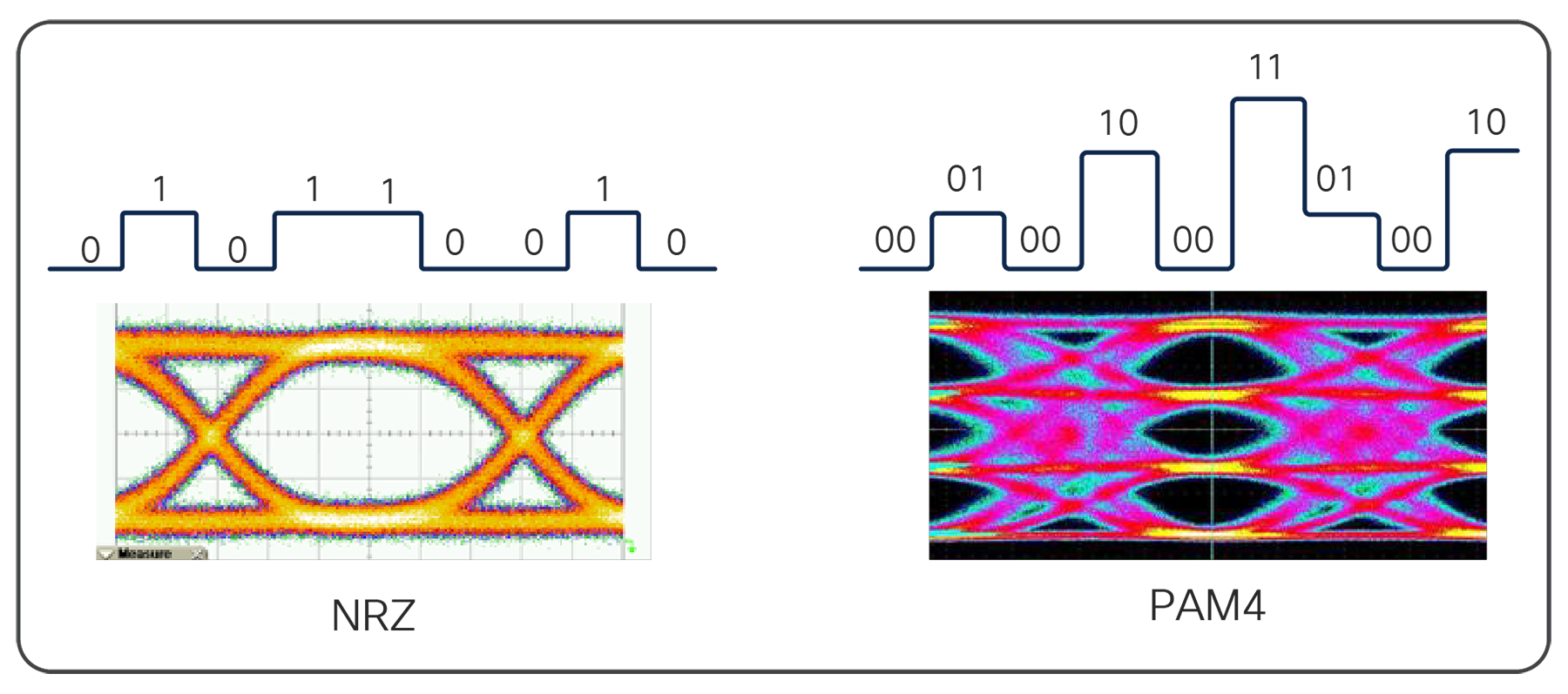
PAM4 carries two bits per pulse, and therefore twice as much information at NRZ
Consider Cisco Optics as your pain-free optics-sourcing team. You can use our pluggable optics in any switch and router with standardized pluggable ports. Known in the transceiver industry for top quality and reliability, we also incorporate features that go beyond industry standards to solve real-world problems for network operators. With Cisco’s award-winning supply chain infrastructure, you can get pluggable optics with a standard two-week lead time and instant support.
Transform your network with world-class optics. Visit Cisco Optics.