Understanding FEC and Its Implementation in Cisco Optics
Available Languages
Bias-Free Language
The documentation set for this product strives to use bias-free language. For the purposes of this documentation set, bias-free is defined as language that does not imply discrimination based on age, disability, gender, racial identity, ethnic identity, sexual orientation, socioeconomic status, and intersectionality. Exceptions may be present in the documentation due to language that is hardcoded in the user interfaces of the product software, language used based on RFP documentation, or language that is used by a referenced third-party product. Learn more about how Cisco is using Inclusive Language.
Why do fiber optic networks need FEC?
The growing popularity of cloud computing, streaming video, and social networking has massively increased internet traffic. To meet the skyrocketing bandwidth demand, the optical networking industry has pushed data rates to 100 Gbps and beyond. Optical transmission is vulnerable to various sources of signal degradation, including chromatic dispersion, modal dispersion, polarization mode dispersion, and noise.
In the real world, an optical receiver’s ability to resolve information is impacted by the presence of noise. As a result, a receiver may not accurately resolve all bits, introducing errors into the data transmission. This problem is exacerbated at higher speeds because receiver filter bandwidths must be widened to allow the faster signals and must also then allow more noise energy to pass through. Fortunately, Forward Error Correction (FEC) can help compensate for this problem. Although the technique can’t correct all errors under all network conditions, when properly specified, it can help network operators run at higher transmission rates while maintaining target Bit Error Ratios (BERs), all while using less expensive optics.
In this white paper, you will learn how FEC works, the trade-offs involved, and how we apply FEC in Cisco equipment. You will come away with a basic understanding of how FEC is used to optimize the performance of your network.
A transmission error occurs when a bit flips from a 1 to a 0 or from a 0 to a 1. Consider a square wave optical pulse in an amplitude-modulated system. The photodetector in the receiver converts optical intensity into voltage. That voltage is read out at a specific sampling point. If the voltage level exceeds the receiver decision threshold at that sampling point, the receiver recognizes the bit as a 1. If the voltage is below the threshold, the bit is read out as a 0.
Ideally, a bit of data would transit the fiber and be read out accurately at the receiver. Unfortunately, networks don’t operate in an ideal world. Optical impairments can distort the pulses during propagation. This can cause pulses to overlap, leading to intersymbol interference (see Figure 1).1 In addition, spreading the optical power into a broader pulse also reduces the amplitude. This effect puts the peaks closer to the threshold, increasing the risk that a noise spike will cause an error.
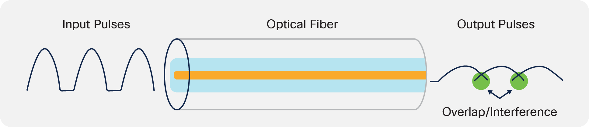
Multimode and single-mode fiber both have dispersive properties. Dispersion effects can broaden pulses enough to introduce intersymbol interference, potentially causing bit errors.
The effects discussed above combine to decrease SNR. Instead of our nice clean pulse, we have broadened pulses with noise, causing intersymbol interference complicated by noise. Because the readout process takes place at a specific sampling point, the same pulse could be read out as a 0 or a 1, depending on the direction of the overlay noise spikes (see Figure 2).
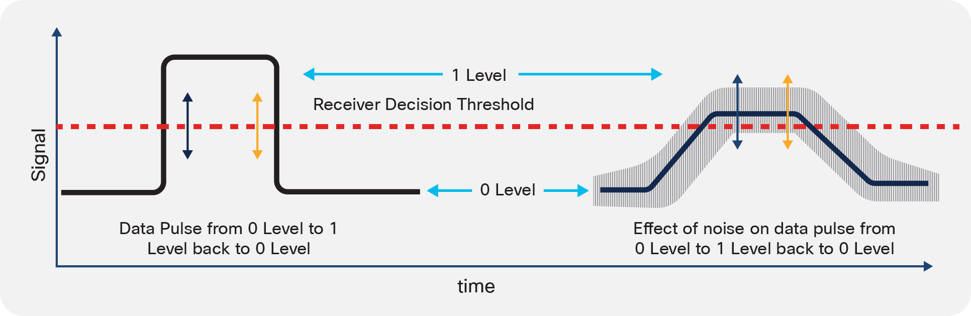
Optical dispersion and electronic noise introduced during transport and detection can combine to degrade an input pulse (left) to the degree that it is misread by the receiver (right). The vertical arrows indicate sampling points, showing how a noise spike can cause the same transmitted pulse to be read out as a 1 (blue arrow) or a 0 (orange arrow).
Data corruption can occur in the form of single-bit errors or burst errors.
● Single-bit errors, or random errors, consist of a data block with a single flipped bit. Single-bit errors can be caused by parallel transmission (for example, due to a noise spike). This can cause the receiver to incorrectly read a bit.
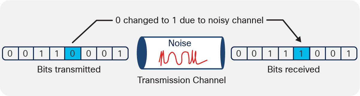
Single-bit errors occur randomly in a data string.
● Burst errors are groups of changed bits. The errored bits in a burst error are not necessarily contiguous (see Figure 4). Burst errors can be generated by impulse failures in the communication system, such as power supply glitches or lightning strikes. Electronic signal conditioning techniques like Decision Feedback Equalization (DFE) and Continuous-Time Linear Equalization (CTLE) can also cause problems. DFE and CTLE are designed to allow recovery of transmitted symbols but have the unfortunate side effect of also amplifying noise and crosstalk, potentially converting a single-bit error into a burst error.
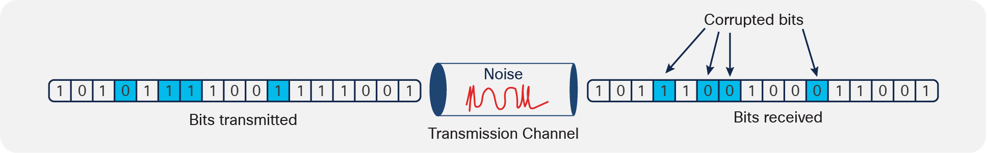
Burst errors can consist of continuous bits or isolated bits.
In order to achieve faster data rates, we need a method to address these problems. That method is FEC, which is used in nearly every optical transport network to at least some degree.
FEC is a technique used to detect and correct a certain number of errors in a bitstream by appending redundant bits and error-checking code to the message block before transmission. The addition contains sufficient information on the actual data to enable the FEC decoder at the receiver end to reconstruct the original message. The FEC decoder can identify the bits received in error and correct them. It then removes the redundant bits before passing the message to the upper layers of the network. Because the FEC decoder uses only the redundant bits to detect and correct errors, it does not request retransmission of the entire errored frame, saving bandwidth that would otherwise be used for retransmission.
FEC uses n symbol codewords consisting of a data block that is k symbols long and a parity block (the code and redundant bits) that is n-k symbols long (see Figure 5). We denote a particular FEC by the ordered pair (n,k). The type and maximum number of corrupted bits that can be identified and corrected is determined by the design of the particular Error-Correcting Code (ECC), so different forward error–correcting codes are suitable for different network implementations and performance levels.

We describe an FEC code using an ordered pair (n, k) in which k denotes the data payload and n denotes the length and symbols of the complete FEC codeword.
FEC starts at the transmitter, where the FEC encoder uses a complex polynomial function to oversample the data block to generate an error polynomial (see Figure 6). The process creates parity bits, appending them to the data block to create the FEC codeword, which is launched into the transmission network.
At the receiver, error detection and correction are based on calculating the “syndrome” of the received codeword. Although the specifics of calculating the syndrome vary from ECC to ECC, in general the syndrome is a mathematical tool for expressing the difference between the transmitted parity and the received parity. If the codeword transmits without error, the syndrome will be zero. If the syndrome vector is nonzero, it can be used to determine the most likely error. As long as the receiver receives many points of the polynomial correctly, it can deduce the form of the original polynomial, then correct and decode the data. Finally, the decoder removes the redundant bits before passing the message to the upper layers of the network.
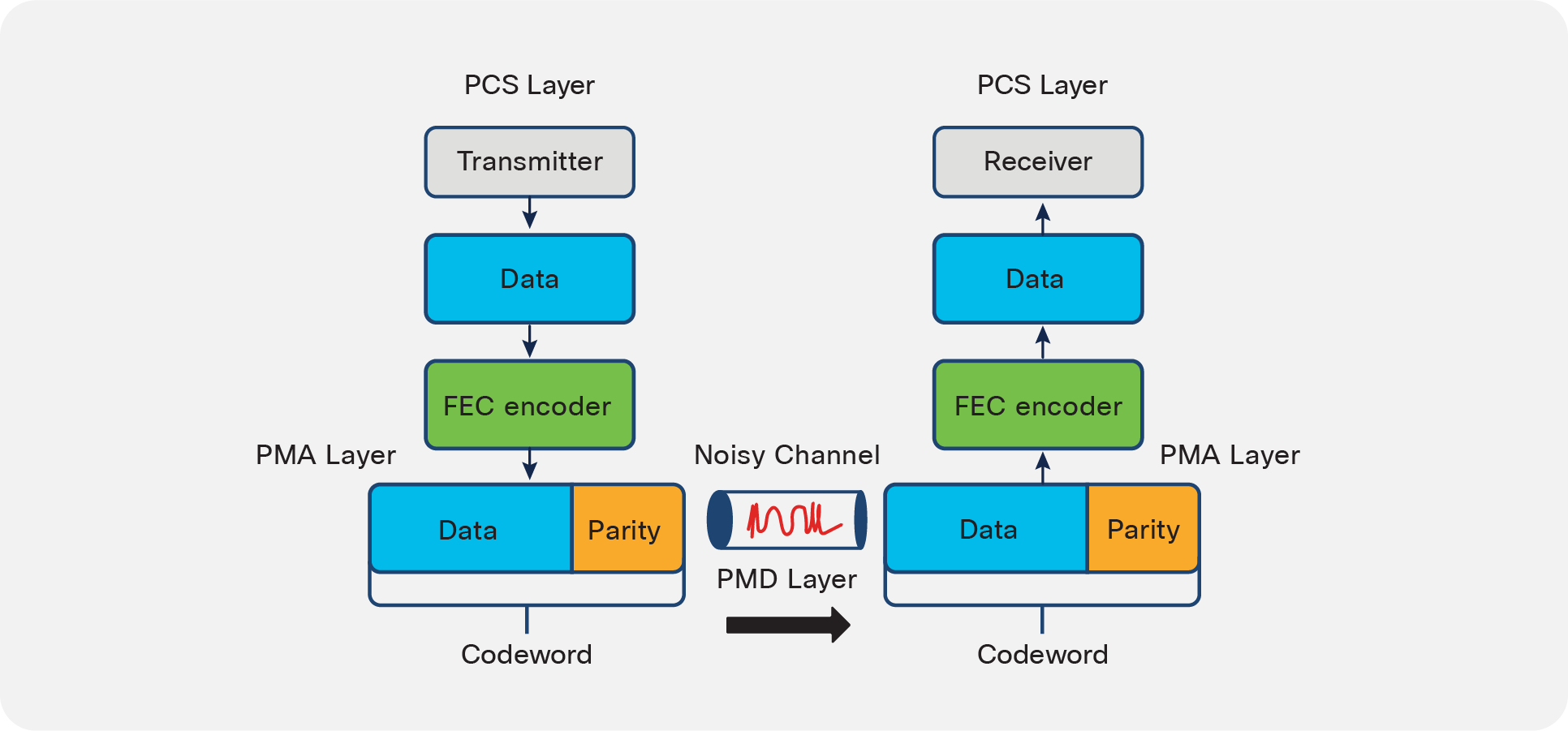
ECC begins in the PCS layer on the transmitter side. The data is run through an FEC encoder algorithm to generate a codeword consisting of the data block and a parity block. On the receiver side, an FEC decoder algorithm analyzes the data to detect and correct any errors.
FEC takes place in the electrical domain. In terms of the seven-layer Open System Interconnection (OSI) reference model, the FEC layer is an element of the PHY, located between the Physical Coding Sublayer (PCS) and the Physical Medium Attachment (PMA) layers (see Figure 7). The FEC block is often in the ASIC of the switch/router. In other cases, for example in certain 100G optics, it is in the module itself.
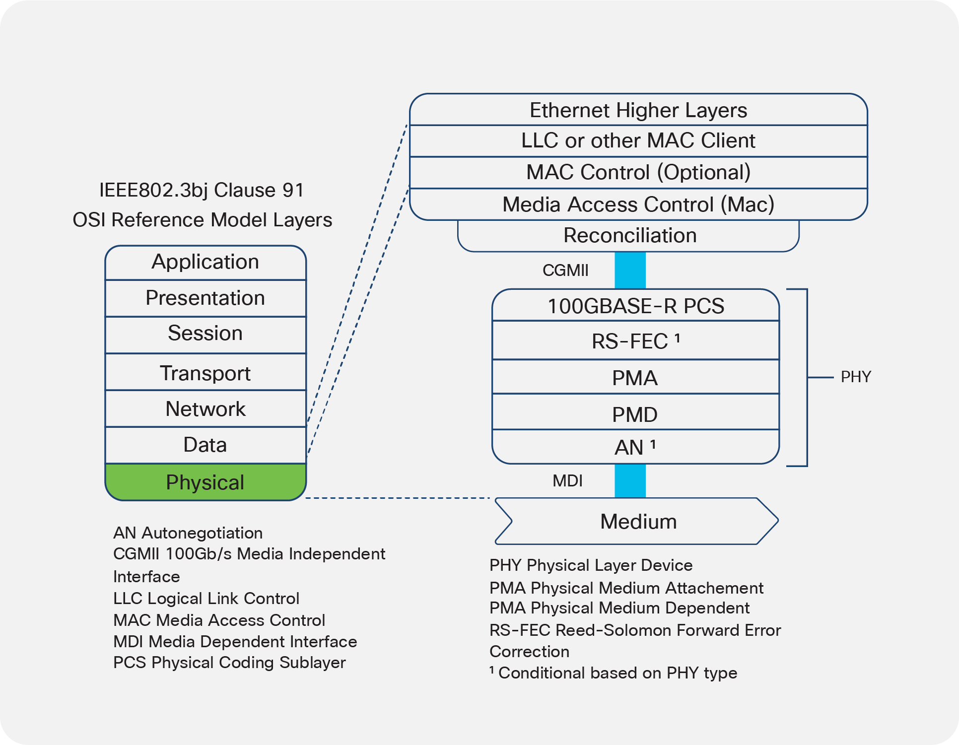
The FEC layer is sandwiched between the Physical Coding Sublayer (PCS), which encodes data bits into code groups for transmission, and the Physical Medium Attachment (PMA) layer, which passes the symbol streams to and from the actual transceivers.
A wide variety of ECCs have been developed to address different network applications and needs.
ECCs can be classed as hard decision or soft decision (see Figure 8). In hard-decision FEC, the receiver makes a decision on the value of a bit as being 0 or 1. Hard-decision FEC encompasses a group of ECCs known as block codes. Block codes use a fixed data block size sent out at fixed spacing. These codes include Reed-Solomon codes, Fire code, and Hamming code, among others.
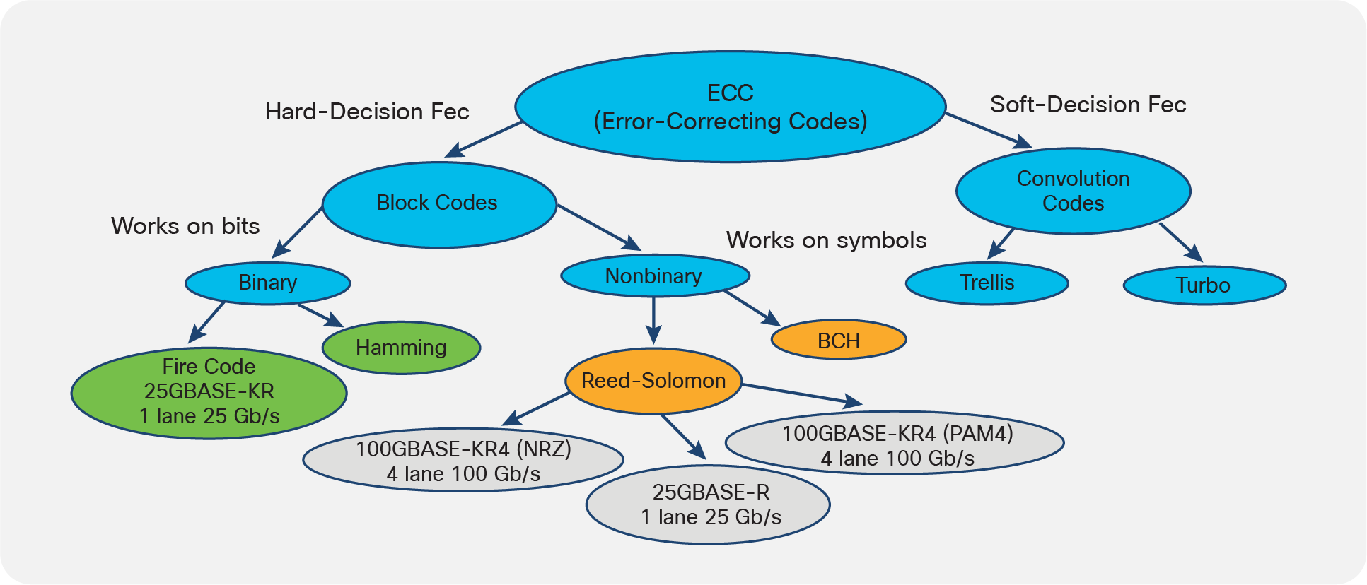
Error-correcting codes can be classed as hard-decision or soft-decision codes. Hard-decision FEC is executed by a group of block codes that use fixed codewords and spacings. Soft-decision FEC is performed by convolutional codes that do not use fixed codewords sizes or spacings.
In soft-decision FEC, the possible value of a bit is divided into multiple levels between 0 and 1. The code uses that data to determine the probability of a bit being a 0 or 1. This approach can yield a coding gain around 3 dB higher than hard-decision FEC. Soft-decision FEC involves highly complex algorithms that are difficult to execute and require more processing time, increasing latency. For these reasons, soft-decision FEC has not been commonly used in optical networking.
Through a combination of Multi-Source Agreements (MSAs) and international standards, the optical communications industry has developed detailed specifications for how and when FEC should be implemented in transport equipment. To release a qualified device, vendors manufacturing pluggable optics and switches and routers must conform to the relevant specifications. The Ethernet Standards (IEEE802.3bj) study group for the backplane and copper cable defined two 100-Gb/s backplane objectives:
● Nonreturn-to-Zero (NRZ) signalling at 25 Gbps: Also known as two-level Pulse Amplitude Modulation (PAM-2), NRZ is used for new backplane designs for high-performance networks that are designed with low-loss backplane materials.
● Four-level pulse amplitude modulation (PAM-4)2 at 12.5 GBaud: In PAM-4, pulse amplitude can be read out as one of four levels. The technique increases bandwidth but the reduced differentiation among amplitude levels can decrease SNR. The PAM-4 PHY is designed to accommodate legacy channels made from lower-performance materials.
The IEEE802.3bj working group investigated various FEC options and explored the trade-offs among latency, coding gain, and complexity. They settled on hard-decision FEC, as it consumed less power and was less complex in architecture than soft-decision FEC (see Figure 6, purple ovals).
Parity check
Parity is a simple method for checking whether a received data block has a bit error. Parity check involves appending a binary bit known as a parity bit to the data block. The value of the parity bit (1 or 0) depends upon whether the number of 1s in the data frame is even or odd. If a single bit flips during transmission, it will change the value of the parity bit and the system will detect an error.
Parity check is only reliable for detecting single-bit errors. It should therefore be reserved for deployments in which errors are expected to be rare and only occur as single bits. If conditions are likely to cause burst errors, then another error detection technique should be used.
Checksum
A checksum is a simple method of redundancy checking used to detect errors in data transmission. In this method, a checksum algorithm operates on the data before transmission to generate a checksum value. This checksum gets appended to the data and sent along with the data frames. The receiver computes a new checksum based on the values of the received data blocks and then compares it with the checksum that was sent by the transmitter. If the two checksums match, then the frame is accepted; otherwise, it is discarded. Checksum is useful for detecting both single-bit and burst errors.
Cyclic Redundancy Check (CRC)
CRC takes advantage of the fact that a binary data block can be expressed as a polynomial. As with integer division, a dividend polynomial can be divided by a divisor polynomial, leaving a quotient with a remainder that can range from zero to some value.
The CRC process starts with generating a polynomial divisor and converting the data block into a polynomial dividend on the transmitter side. Next, the data polynomial is divided by the polynomial divisor. The remainder is subtracted from the quotient, and this value is appended to the data block. At the receiver end, the received bitstream is once again converted to a polynomial dividend. When it is divided by the quotient and the remainder that is sent in the codeword is subtracted, the result should be zero. If it is not, an error has occurred. CRC is effective for both single-bit and burst errors.
Reed-Solomon (RS) codes
Reed-Solomon (RS) codes are widely used ECCs. The algorithms operate on symbols rather than on individual bits. The technique used in RS-FEC is similar to that described above where the data to be encoded is first expressed as a polynomial. The transmitter encodes that polynomial and sends it along with the data (see Figure 9).
At the receiver side, the algorithm performs polynomial division to determine the syndrome of the codeword. If the syndrome is zero, the codeword is run through the FEC decoder to extract the data block.
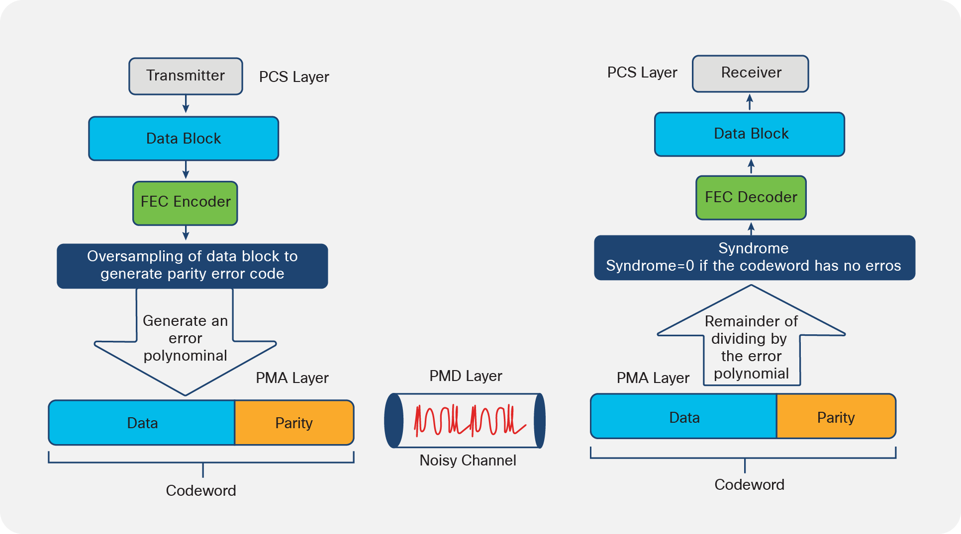
Reed-Solomon ECCs use oversampling and error polynomials to generate a codeword at the PMA layer. After propagation through the network, the codeword undergoes polynomial division. If the result matches that of the transmitted polynomial, the syndrome is zero and the codeword has no errors. It is then run through the FEC decoder to discard the parity block and retrieve the data block.
RS codes can correct a series of errors in a block of data. Because they are so effective at dealing with random and burst errors, as well as minimizing latency, RS ECCs have been widely adopted by optical communications standards and multi-source agreements such as the 100G Lambda MSA.
Fire codes
Fire codes are a family of binary block ECCs that operate on bits. They are highly effective for single-burst (versus single-bit) errors.
The IEEE 802.3 standard defines KR-FEC and KP-FEC, where “K” denotes the FEC used on backplanes. KR-FEC is used for NRZ signals, and KP-FEC is used for PAM-4 signals. KR1-FEC translates 4x25G NRZ electrical signals into a 100GBASE-KR1 encoded signal. KR-FEC is denoted as RS(528, 514). Here, the RS encoding starts with a 514-symbol data field (k), where each symbol consists of 10 bits and appends 14 parity symbols to form a 528-symbol encoded codeword (n).
KP-FEC can be applied to both 100G (KP1) or 400G (KP4) signals. KP1-FEC is applied to PAM-4 signals to group two 50-Gbit PAM-4 electrical signals into a single 100GBASE-KP1 encoded signal. KP1-FEC translates 30 parity symbols, in which each symbol consists of 10 bits. This parity string gets appended to a 514-symbol data field (k) to form a 544-symbol encoded codeword (n), so KP1-FEC is denoted as RS(544,514).
PAM-4 signals have a tighter spacing between voltage levels, reducing the eye amplitude to one-third that of a similar NRZ signal. This results in the PAM-4 signal having a lower SNR and being more susceptible to noise. To compensate for the reduced SNR, KP-FEC is specified to have a stronger coding gain. KP-FEC can potentially correct up to 15 symbols per codeword, compared to KR-FEC, which can correct a maximum of just seven symbols.
The coding techniques used in FEC reduce the SNR necessary for a link to operate at a specified BER. In effect, the link performs as though operating with a much higher SNR. Thus, we refer to the figure of merit for an FEC scheme as coding gain.
FEC provides a way for networks to increase data rate while maintaining an acceptable BER. There are trade-offs, however. The improvement is the result of adding overhead in the form of error-correcting parity bits, which consumes some of the available bandwidth. In general, the higher the coding gain, the greater the number of parity bits, which increases the size of the codewords. FEC decoders need to receive the full codeword before they can act on it. Stronger FEC algorithms might offer higher coding gains, but they require larger codewords, and larger codewords increase latency.
We should make two observations about this relationship. First, FEC reaches a point of diminishing returns. This is particularly the case given that there is an absolute limit to the number of errored bits that a given FEC scheme can correct. Second, for the FEC specifications in the various standards and MSAs, the latency increase is limited. For a few applications like high-speed online trading, it might be a consideration. For the vast majority of use cases, the effect is insignificant and far outweighed by the benefits of FEC.
Cisco optics and FEC implementation
As a module manufacturer, we take care to design our transceivers to comply with specifications. When the optical transceiver is operated in a Cisco host platform, the FEC is enabled by default based on the optical module type that the host software detects (See this downloadable table)4. In the vast majority of cases, the FEC implementation is dictated by the industry standard that the optic type supports. For certain custom specifications, FEC implementations may vary. Cisco’s QSFP-100G-ZR4-S specification, for example, is an 80-km Cisco specification that requires host-enabled FEC.
The default FEC is enabled automatically; however, there could be other FEC codes for specific application protocols that can be supported by the host software. The user can decide to enable these, depending on their specific application.
Here, we outline the various Cisco part IDs and the associated FEC implementation.
Active optical cables
As previously mentioned, the specific FEC code is generally called out by the standards. Our Active Optical Cables (AOCs) are not based on an industry optical specification for the link, because they form a closed system. The electrical connectors at either end of the AOC must comply with electrical specifications for C2M TJP1/TP4 as outlined in the IEEE802.3 industry specification, however. In this case, the optics and the fiber optical cable used for transmission are designed to control the dispersion and losses, to ensure the AOC operates with a BER better than 1E-8. Enabling host FEC ensures that the BER is better than 1E-12.
100GBASE-LR4, 100GBASE-ER4, and FEC
With the exception of 100GBASE-LR4 and 100GBASE-ER4 (40 km), 100G optics require RS(528,514) (based on IEEE802.3 CL91 FEC) enabled on the host. Users sometimes wonder why the FEC requirement does not also extend to 100GBASE-LR4 and 100GBASE-ER4.
100GBASE-LR4 and 100GBASE-ER4, defined in IEEE802.3ba, use LAN-WDM transmitters (four channels with 5-nm spacing: 1295, 1300, 1305, 1310 nm). The wavelengths are controlled very tightly, and there is little wavelength drift over temperature, which results in a lower dispersion penalty over fiber. These transmitters are more tolerant to the effects of dispersion. As a result, even without host FEC, 100GBASE-LR4 can support a single-fiber reach of up to 10 km with a BER of less than 1E-12.
In addition, 100GBASE-ER4 also specifies a high-sensitivity avalanche photodiode (APD) receiver. The combination increases the link budget to compensate for high chromatic dispersion over 30 km of single-mode fiber. This module is designed to ensure a BER of less than 1E-12 over 30 km without host FEC.
In contrast, 100G CWDM4 optics are standardized by MSA to the CWDM wavelength grid. This grid has a more relaxed wavelength spacing four channels with 20-nm spacing (1270, 1290, 1310, 1330 nm), with a required BER of less than 1E-12 over a reach of up to 2 km.3
100G Lambda modules
In all cases, the host platform software will detect the optics type and enable the appropriate FEC for that port. However, there is one variant in the FEC configuration for the newly released single-lambda 100G form factors.
The following modules have internal RS(544, 514) KP1-FEC to ensure the BER is better than 1E-12:
● The 100G Lambda IEEE 802.3cd and 802.3cu modules, which are based on PAM-4 modulation
◦ 100GBASE-DR, operating over 500 m
◦ 100GBASE-FR, operating over 2 km
◦ 100GBASE-LR, operating over 10 km
● The custom 100G-ERL, operating over 25 km
For these devices, the FEC function is built into the digital signal processor (DSP) chip internal to the module. When modules are populated into a Cisco host platform, the software automatically detects this optics type and disables the host-side FEC. Also, these modules can be configured to bypass KP-FEC, if available from the host.
100GBASE-LR and 100G-ERL can also be configured to bypass KR FEC from the host, if the link condition allows to trade off less correction (as said, KR is RS(528, 514)) with rate advantage (51.5625 GBaud rate against 53.125 GBaud of the data encoded with KP FEC).
400G QSFP-DD optics, which are based on PAM-4 modulation, require the host to enable FEC (544,514). One of the use cases, especially for data center and service provider customers, is to support physical breakout from 400G QSFP-DD to 100G Lambda modules (namely 400G QSFP-DD DR4) or LR4 breakout to 4x100G (DR, FR, or LR) Lambda optics on the remote side.
The FEC configuration is for the 400G QSFP-DD to enable 400GBASE-R KP4 FEC, and the remote-side 4x100G Lambda module FEC would terminate the KP4 FEC and enable internal KR4 FEC.
Better network operation with FEC
A high-speed network is useless if it can’t accurately transmit data. As data rates rise, FEC provides an essential tool for identifying and correcting errored bits without significantly impacting network performance. Just as important, from the standpoint of the network operator, FEC enables them to perform this magic while using less expensive optics. Which type of FEC to use is typically specified by standards/MSAs and implemented in the hardware and software. FEC can seem complex, but it doesn’t have to be. At Cisco, we comply with all standards and enable FEC in our products by default. The goal is to simplify integration and minimize effort on behalf of network integrators and operators while delivering the performance they expect.
Reach out to your Cisco partner or visit us online [cisco.com/go/optics] to learn more about FEC and our products.
References
1. “Fiber Optics Part 3: Fiber Dispersion Will Change The Way You See Your Links,” https://tinyurl.com/y3oaxr7j
2. “PAM4 for 400G Optical Interfaces and Beyond (Part 1),” https://tinyurl.com/2p8dm73b
3. “100G Lambda MSA Group Adds New Members and Releases Updated Specifications for Next Generation Networks,” https://tinyurl.com/2p8pmx7m
4. Download this table for more details on FEC types for each Cisco optic: https://www.cisco.com/c/dam/en/us/products/se/2022/4/Collateral/fec-summary-table.pdf
Cisco Optics blog posts related to FEC
Extended Reach 100G Optics – Which One Is Best for Me? [https://tinyurl.com/2p8vdjtx]
Don’t Mix Up Your FECs [https://blogs.cisco.com/sp/dont-mix-up-your-fecs]