A move to high speed server connectivity in the cloud White Paper
Available Languages
Bias-Free Language
The documentation set for this product strives to use bias-free language. For the purposes of this documentation set, bias-free is defined as language that does not imply discrimination based on age, disability, gender, racial identity, ethnic identity, sexual orientation, socioeconomic status, and intersectionality. Exceptions may be present in the documentation due to language that is hardcoded in the user interfaces of the product software, language used based on RFP documentation, or language that is used by a referenced third-party product. Learn more about how Cisco is using Inclusive Language.
Data centers consisting of hundreds of thousands of servers process massive amount of data driven by cloud computing and big data applications as well as new and emerging workloads such as AI/ML (artificial intelligence/machine learning). These emerging workloads, which may span different geographical areas, need greater bandwidth and higher efficiency when having to interconnect compute, storage, and memory across and/or within a rack at higher speeds. In this paper, Cisco and Panduit will describe some of the trends in data center connectivity and the impact this compute-intensive workload have on cabling and network infrastructure design with corresponding deployment guidelines.
Applications like machine learning or AI are compute intensive and are processed across multiple servers, physical and virtual, all interconnected locally within or across multiple racks requiring bandwidth to be distributed within and across multiple facilities. To address the bandwidth requirements or potential bottlenecks within the data center, the switching, compute to network bandwidth, and cabling infrastructure needs to evolve both in terms of speed and network placement.
Let’s look at some of the trends within the data center infrastructure—switch architecture, compute to network PCIe bandwidth evolution and switch to server connectivity speeds and deployment models:
● Switching and server port transitions to higher speeds
● Upward evolution of switch ASICS enabling greater bandwidth connectivity in the rack
● Upward evolution of the PCIe bandwidth driving higher Ethernet port speeds in the NIC
Switching and server port speed transitions
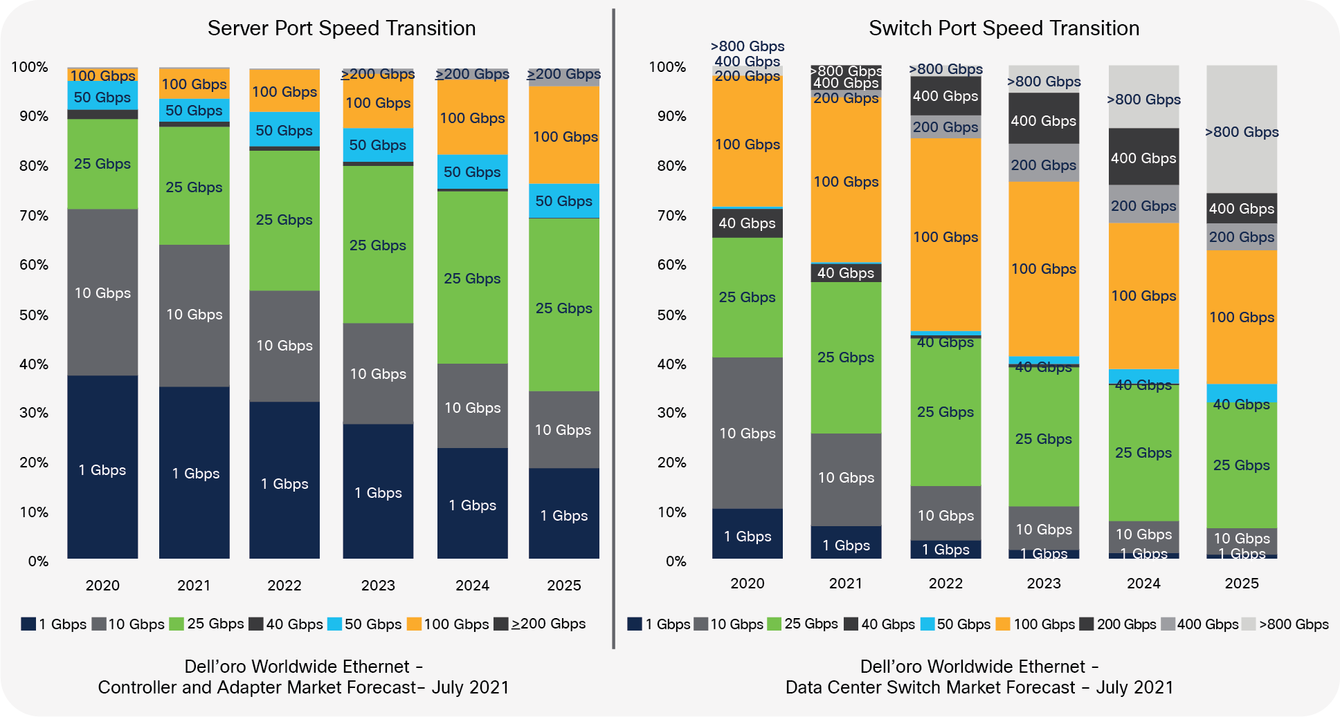
While today most of the switch ports are at 100 Gbps or below, the expectation is that, by 2025, more than 60% of the switch ports will be 100 Gbps or higher as shown in Chart 1 below. This growth in switch port speed is also met by higher uplink speeds from the server to the network. Server connection speeds are also transitioning from 1/10 Gbps to 25 Gbps and above. While today for most data centers the connectivity between the server and the switch is at 1G or 10G, the expectation is by 2025, 60% of the ports facing the switch will be at speeds above 10 Gbps with 25 Gbps, comprising close to 30% of the interconnection speeds at shown in Chart 2 below:
Switch and Server Connectivity Speed Transitions
To address higher bandwidth requirements, the switch silicon must scale either through an increase in switch radix or lane bandwidth. An increase in switch radix means adding more pins to a switch ASIC, making the network more efficient by reducing hops, power, and cost.
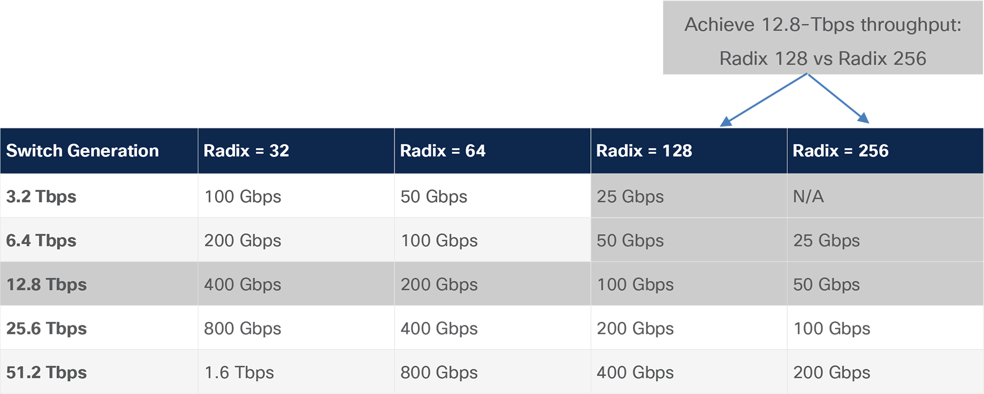
Table 1 below shows the various ASIC throughputs and the lane speed and count required to achieve the corresponding throughput. So, one way to achieve a 12.8-Tbps throughput is to use 100G Serdes with a radix count of 128. The 12.8-Tbps throughput can also be achieved using different Serdes speeds and/or radix count as shown in Table 1 below:
Table 1. Switch generation and the corresponding throughput
The radix count is significant because as you increase the radix count, your overall throughput increases, and the number of connections also increases, which means a single switch can support more servers within or across multiple racks as shown in Table 2 below:
Table 2. Switch generation and the corresponding throughput
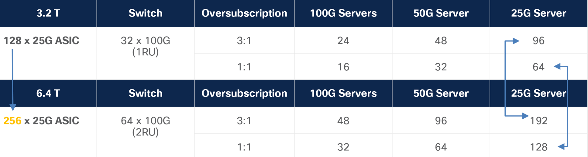
In the example above, by increasing the radix count from 128 to 256, assuming the server port speed is constant, in both an oversubscribed and nonblocking model, you can double the number of servers supported by a single switch. This is a key factor when deciding where to place the switch for optimal return on investment, which in turn has a direct impact on connectivity options between the switch and the server.
Evolution of the PCIe bandwidth driving higher Ethernet port speeds in the NIC
As applications become more bandwidth hungry, the connectivity between the compute and the network must also scale up to meet the new demand. PCIe is the interface that connects the compute domain to the network domain, and with CPUs and GPUs becoming faster and more powerful, the PCIe I/O bandwidth must also increase.
I/O bandwidth doubles every three years, going from maximum bandwidth of 32 GB with PCIe Gen 4.0 in 2017 to 64 GB with PCIe Gen 5.0 in 2019 to the future PCIe Gen 6.0 delivering 128-GB/sec throughput. The PCIE speed increases through lane bandwidth and/or number of lanes as shown in Table 3 below:
Table 3. Evolution of the PCIe Bandwidth
| Ports |
Modulation |
BW per lane in Byte/sec |
BW per lane in Bits /sec |
x8 |
x16 |
x32 |
| PCle Gen2 |
NRZ |
0.625 GByte/sec |
5.0 Gbps |
40 Gbps |
80 Gbps |
160 Gbps |
| PCle Gen3 |
NRZ |
1.0 GByte/sec |
8.0 Gbps |
64 Gbps |
128 Gbps |
256 Gbps |
| PCle Gen4 |
NRZ |
2.0 GByte/sec |
16.0 Gbps |
128 Gbps |
256 Gbps |
512 Gbps |
| PCle Gen5 |
NRZ |
4.0 GByte/sec |
32.0 Gbps |
256 Gbps |
512 Gbps |
1024 Gbps |
| PCle Gen6 |
PAM-4 |
8.0 GByte/sec |
64.0 Gbps |
512 Gbps |
1024 Gbps |
2045 Gbps |
With higher PCIe bandwidth, the server ports connecting upstream to the network will also have to migrate to higher speeds.
Lane bandwidth increase can be done by switching from a non-zero return (NRZ) encoding to Pulse Amplitude Modulation (PAM) signaling, effectively doubling the bandwidth on a lane. Today, PCIe Gen6 is the first generation to use PAM-4 modulation and is expected to become available in 2022 for commercially available network interface cards.
Based on the Ethernet port of the network interface card, the minimum required PCIe generation and lane count is shown in the table below for 100% utilization:
Table 4. Minimum PCIE generation to achieve 100% utilization
| Ports |
10 Gbps |
25 Gbps |
40 Gbps |
50 Gbps |
100 Gbps |
200 Gbps |
400 Gbps |
| Single |
PCle Gen2 x4 |
PCle Gen2 x8 |
PCle Gen3 x8 |
PCle Gen3 x8 |
PCle Gen3 x16 |
PCle Gen3 x32 |
PCle Gen5 x16 |
| Double |
PCle Gen2 x8 |
PCle Gen3 x8 |
PCle Gen3 x16 |
PCle Gen3 x16 |
PCle Gen4 x16 |
PCle Gen4 x32 |
PCle Gen5 x32 |
Alternatively, if 100% utilization is not required, earlier PCIe generations can be used for dual 100G/200G or 400-Gbps Ethernet ports on NICs as shown in Table 5 below:
Table 5. Ethernet port to PCIE with utilization numbers
| Ports |
Aggregate Bandwidth |
PCle Gen3 |
PCle Gen3 |
PCle Gen4 |
PCle Gen4 |
PCle Gen5 |
PCle Gen5 |
PCle Gen6 |
PCle Gen6 |
| 2 X 10 Gbps |
20 Gbps |
100% |
100% |
100% |
100% |
100% |
100% |
100% |
100% |
| 2 X 25 Gbps |
50 Gbps |
100% |
100% |
100% |
100% |
100% |
100% |
100% |
100% |
| 2 X 40 Gbps |
80 Gbps |
100% |
100% |
100% |
100% |
100% |
100% |
100% |
100% |
| 2 X 50 Gbps |
100 Gbps |
100% |
100% |
100% |
100% |
100% |
100% |
100% |
100% |
| 2 X 100 Gbps |
200 Gbps |
64% |
100% |
100% |
100% |
100% |
100% |
100% |
100% |
| 2 X 200 Gbps |
400 Gbps |
32% |
64% |
64% |
100% |
100% |
100% |
100% |
100% |
| 2 X 400 Gbps |
800 Gbps |
16% |
32% |
32% |
64% |
64% |
100% |
100% |
100% |
Growth in server ports and the impact it has on the cabling design
So, how does port speed transition and ASIC and PCIe throughput evolution impact the cabling infrastructure within a data center? The need for more bandwidth within a data center is driven primarily by compute-intensive applications such as AI/HPC or ML. These applications not only require more intra-rack throughput, but also, due to the nature of the traffic pattern, require much more processing at the inter-rack level, which means more traffic must traverse the switch. Within the rack, throughput can increase either through adding more servers or deploying higher speed uplinks on servers. Due to power constraints, adding servers may not always be possible. So, let’s consider the option of moving to higher speed on server uplinks.
As mentioned above, server connectivity is moving to higher speeds with interface types being SFP28 for 10/25 Gbps, QSFP28 for 100 Gbps, SFP56 for 10/25/50 Gbps, SFP-DD for 100 Gbps, or QSFP56 for 100/200 Gbps. At higher speeds there are three factors to consider. The first is as connections go to higher speeds, there is a reach limitation when using Direct Attach Copper (DAC) cables. At speeds higher than 25G, copper cables may only support up to 5 meters or less. So, if a single switch in the past could manage multiple racks using DAC, with a limitation of 5 meters or less with speeds above 25 Gbps, this is no longer a viable option.
The second factor is the power consumption by servers, which may limit the number of servers deployed within a rack. Where DC operators may have had over 42 servers per rack, they now must depopulate and limit the number of servers in a rack to 32 or less. This leads to a sparsely populated rack managed by a single top-of-rack switch that is inefficient and costly. The cost factor becomes even more significant given that some architectures require connecting a server to two top-of-rack switches for redundancy. If the physical space in the cabinet is exhausted before the networking ports on the switch are fully utilized, there is no other option but to either accept less than 100% utilization of the switch ports or downgrade to a less expensive switch that has fewer network ports—leaving one or more units of rack space unused. So, there is a need for a cabling model that allows 100% utilization of switch ports while fully utilizing rack space.
And the third, which might be the most important, is that, with switches capable of higher throughput and radix count, a single switch can manage many more servers. This means that data center operators may choose to move from a 1:1 switch-to-rack configuration to a more cost-effective Middle-Of-Row (MOR) or End-Of-Row (EOR) model as shown in Figure 1 below. In the topology below, a 32 x 400G Gbps port switch deployed in the middle or end of row will connect downstream with 16 of the 400-Gbps ports utilized as 100-Gbps ports connecting to 16 servers using 100-Gbps DAC. With 16 ports as uplinks, the switch can connect to an additional 64 servers downstream at 25 Gbps using a 100-Gbps to 25-Gbps breakout solution.
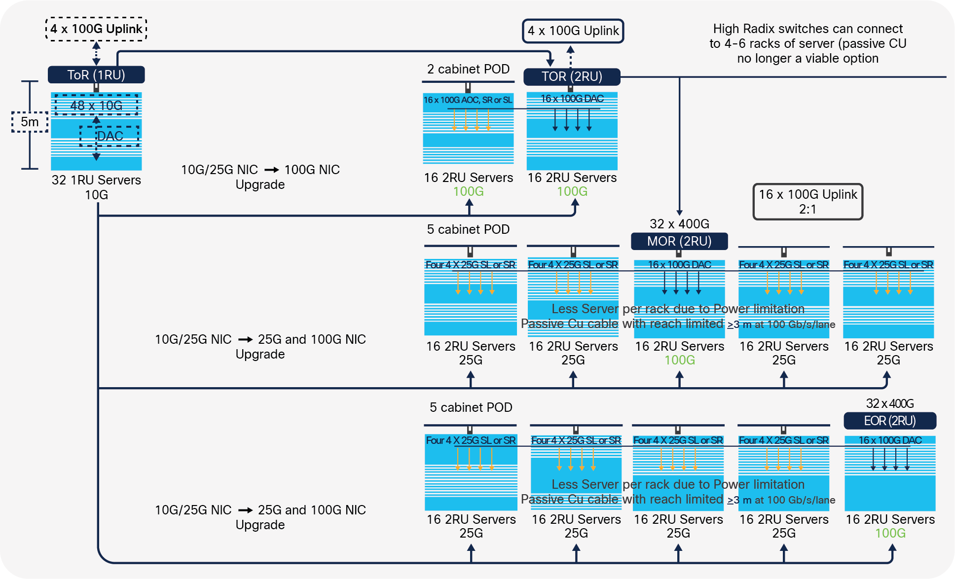
Transition from TOR to EOR/MOR for sparsely populated racks using high-radix switches
So, a single switch can interconnect many more servers across multiple racks effectively increasing the distance between the switch and the servers.
So, what will be the connectivity option if copper has reached limitations at higher speeds? There are several alternative options available for data center operators. One is to use Active Optical Cables (AOCs), which would extend the reach to 30 meters, enough to populate multiple racks. AOCs are also lighter and less bulky, which helps in manageability. The second option would be to use pluggable transceivers. The value in pluggable transceivers is that not only can you extend the reach to 100 meters or more, but also the manageability is much more efficient compared to cables, particularly when you go beyond 15 m. With pluggable transceivers, the endpoints are field replaceable, and so, in the event of a failure, only the endpoints are replaced, as opposed to having to swap out the entire cable. The second benefit of using pluggable transceivers is that as you migrate to higher speeds the existing fiber infrastructure can be maintained so the investment is protected. There is also a third option that allows an AOC-type solution with field-replaceable endpoints, allowing customers to connect to 30 meters with the ability to swap out endpoints in the event of a failure. This is particularly attractive at lengths exceeding 15 meters and is shown above using the Cisco® SL (Short Link) nomenclature.
Below are a couple of deployment scenarios that Panduit and Cisco have put together to illustrate the changes discussed earlier in this paper.
The scenario in Figure 2 is offering an alternative to the traditional data center switch-server connectivity setup. In this scenario, a five-cabinet POD deployment is utilized with (16) 2RU servers in each cabinet using a single 48-port 400G switch. It’s a hybrid model of (16) 100G servers in the middle cabinet and (64) 25G servers in the remote cabinets. This switch is providing (64) ports of 25G achieved by using (16) ports of 100G in breakout mode (4x25G downlinks), 16 ports of 100G, and (16) ports of 100G uplinks delivering a 2:1 oversubscription.
For the server to switch connectivity, 100G to 4x25G breakouts are achieved by using the SL transceivers in breakout mode, going to each cabinet where it’s broken down into 4 LC connections using Panduit Breakout Cassettes. These SL transceivers are Active Optical Cable (AOC)–like solutions, limited to 30 meters, with endpoints that are field replaceable. The 100G connections in the middle cabinet are achieved by utilizing Panduit or Cisco 100G DACs.
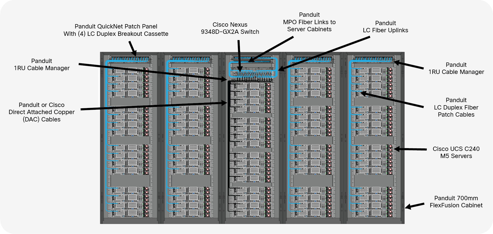
Five cabinet POD with 16 servers each – (64) ports of 25G achieved by using (16) ports of 100G in breakout mode, (4x25G downlinks), (16) ports of 100G, and (16) ports of 100G uplinks for a 2:1 oversubscription.
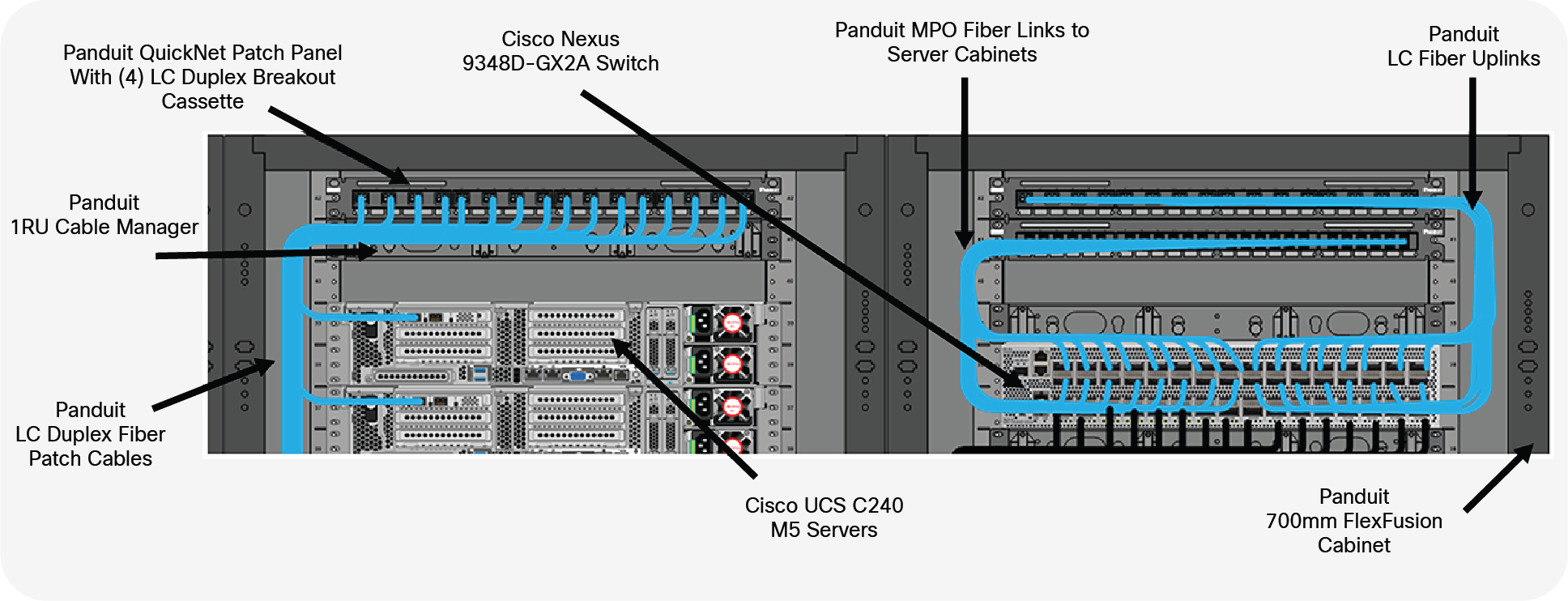
Closeup of breakout cassette in the server cabinet and the cabling in the switch cabinet.
Table 6. Cisco Nexus 9300-GX2A switch
| Switch |
Description |
| Nexus N9K-C9348D-GX2A |
Nexus 9300 48 ports 400G Switch, MACsec Capable |
Table 7. Cisco UCS C240 M5 Rack Server
| Server |
Description |
| UCSC-C240-M5SX: |
Cisco UCS C240 M5 24 SFF + 2 rear drives w/o CPU, mem, HD, PCIe, PS |
Table 8. Cisco 100 Gbps and 100G to 25 Gbps copper breakout cable
| 100G Copper Cables |
Description |
| QSFP-100G-CU1M |
100GBASE-CR4 Passive Copper Cable, 1m |
| QSFP-4SFP25G-CU2M |
100GBASE QSFP to 4xSFP25G Passive Copper Splitter Cables, 2m |
| QSFP-4SFP25G-CU3M |
100GBASE QSFP to 4xSFP25G Passive Copper Splitter Cables, 3m |
| QSFP-4SFP25G-CU5M |
100GBASE QSFP to 4xSFP25G Passive Copper Splitter Cables, 5m |
Table 9. Cisco 100 Gbps and 100 Gbps to 25 Gbps breakout Short Link Pluggable
| Pluggable SL (Short Link) |
Description |
| QSFP-100G-SL4 |
Cisco 100GBASE SL4, up to 30M over OM4 MMF |
| SFP-25G-SL |
Cisco 25GBASE SFP SL, up to 30M over OM4 MMF |
| QSFP-100G-SL4 + 4 x SFP-25G-SL |
Cisco 100GBASE SL4 to 4 Cisco SFP-25G-SL, up to 30M over OM4 MMF |
Table 10. Cisco 100 Gbps and 10/25 Gbps Transceivers
| Pluggable Transceivers |
Description |
| QSFP-100G-SR4-S |
Cisco 100GBase SR4 QSFP Transceiver, MPO, 100m over OM4/5 |
| QSFP-40/100G-SRBD |
Cisco 100GBase SR4 QSFP Transceiver, LC Duplex, 100m over OM4/5 |
| SFP-25G-SR-S |
Cisco 25GBASE-SR SFP28 Module, LC Duplex, 100M over OM4/5 |
| SFP-10/25G-CSR-S |
Cisco 25GBASE-SR SFP28 Module, LC Duplex, 100M over OM4/5 |
Table 11. Cisco 10Gbps and 25Gbps Network Interface Cards
| Network Interface Card |
Description |
| UCSC-PCIE-C25Q-04 |
Cisco VIC 1455 VIC PCIE – Quad Port 10/25G SFP28 |
| UCSC-MLOM-C25Q-04 |
Cisco UCS VIC 1457 Quad Port 25G SFP28 mLOM |
| UCSC-PCIE-QD25GF |
QLogic QL41212H Dual Port 25Gb NIC |
| UCSC-PCIE-ID25GF |
Intel XXV710 Dual Port 25Gb SFP28 NIC |
| UCSC-P-M4D25GF |
Mellanox MCX4121A-ACAT dual port 10/25G SFP28 NIC |
| UCSC-P-M5D25GF |
Mellanox CX-5 EN MCX512A-ACAT 2x25/10GbE SFP PCIe NIC |
| UCSC-P-I8Q25GF |
Cisco-Intel E810XXVDA4L 4x25/10 GbE SFP28 PCIe NIC |
| UCSC-P-I8D25GF |
Cisco-Intel E810XXVDA2 2x25/10 GbE SFP28 PCIe NIC |
| UCSC-PCIE-C100-04 |
Cisco UCS VIC 1495 2x 40/100G QSFP28 PCIe for C220 M5/M6, C240 M5/M6 |
| UCSC-MLOM-C100-04 |
Cisco UCS VIC 1495 2x 40/100G QSFP28 mLOM for C220 M5, C240 M5 |
| UCSC-P-M5S100GF |
MELLANOX CX-5 MCX515A-CCAT 1x100GbE QSFP PCIe NIC |
| UCSC-P-M5D100GF |
MELLANOX CX-5 MCX516A-CDAT 2x100GbE QSFP PCIe NIC |
| UCSC-P-I8D100GF |
Intel E810CQDA2 2x100 GbE QSFP28 PCIe NIC |
Source: https://tmgmatrix.cisco.com/
Table 12. Panduit Direct attach copper cables with Fiber and Cabinet Connectivity
| SKU |
Description |
|
|
Direct Attached Copper Cables 100G |
| PQSF2PXA1MBL |
QSFP28 100G Direct Attach Copper Cable Assembly, 30 AWG, Black, 1m |
| PQSF2PXA2MBL |
QSFP28 100G Direct Attach Copper Cable Assembly, 30 AWG, Black, 2m |
| PQSF2PXA3MBL |
QSFP28 100G Direct Attach Copper Cable Assembly, 30 AWG, Black, 3m |
|
|
Cabinet and Fiber Connectivity |
| FZTRR7N7NYNF001 |
OM4 12 fiber PanMPO Interconnect, Female to Female, Method B, 1ft |
| QPP24BL |
QuickNet 24-port Patch Panel |
| FQMAP66CG |
Fiber Optic Migration Adapter Panel - 6 MPO Adapters – Type B |
| FYZTP78Y001F*** |
OM4 12 fiber PanMPO Trunk Cable, Male to Female, Method B, various lengths |
| FQ3ZO-08-10B |
QuickNet SFQ 4 to 1 Breakout Cassette, Method B |
| FZ2ERLNLNSNM*** |
OM4 2 fiber LC Duplex Patch Cord, various lengths |
| CMPH1 |
Panduit Cable Manager 1 RU |
| XG74222BS0001 |
Panduit FlexFusion Cabinet 700mm 42RU 1200mm deep |
The scenario in Figure 4 is offering another alternative to the traditional data center switch-server connectivity setup. In this scenario, a two-cabinet POD deployment is utilized with (16) 2RU servers in each cabinet using a single 48-port 400G switch. It’s a spilt model of (16) 100G servers in the switch cabinet and (16) 100G servers in the remote cabinet. This switch is providing (16) ports of 100G achieved by using (16) ports of 100G utilizing Panduit or Cisco 100G DACs, (16) ports of 100G achieved by using (16) ports of 100G utilizing Panduit 100G AOCs, and (16) ports of 100G fiber uplinks delivering a 2:1 oversubscription. The copper DACs are used in the cabinet where the switch resides, and the AOCs are utilized in the remote cabinet due to length restrictions.
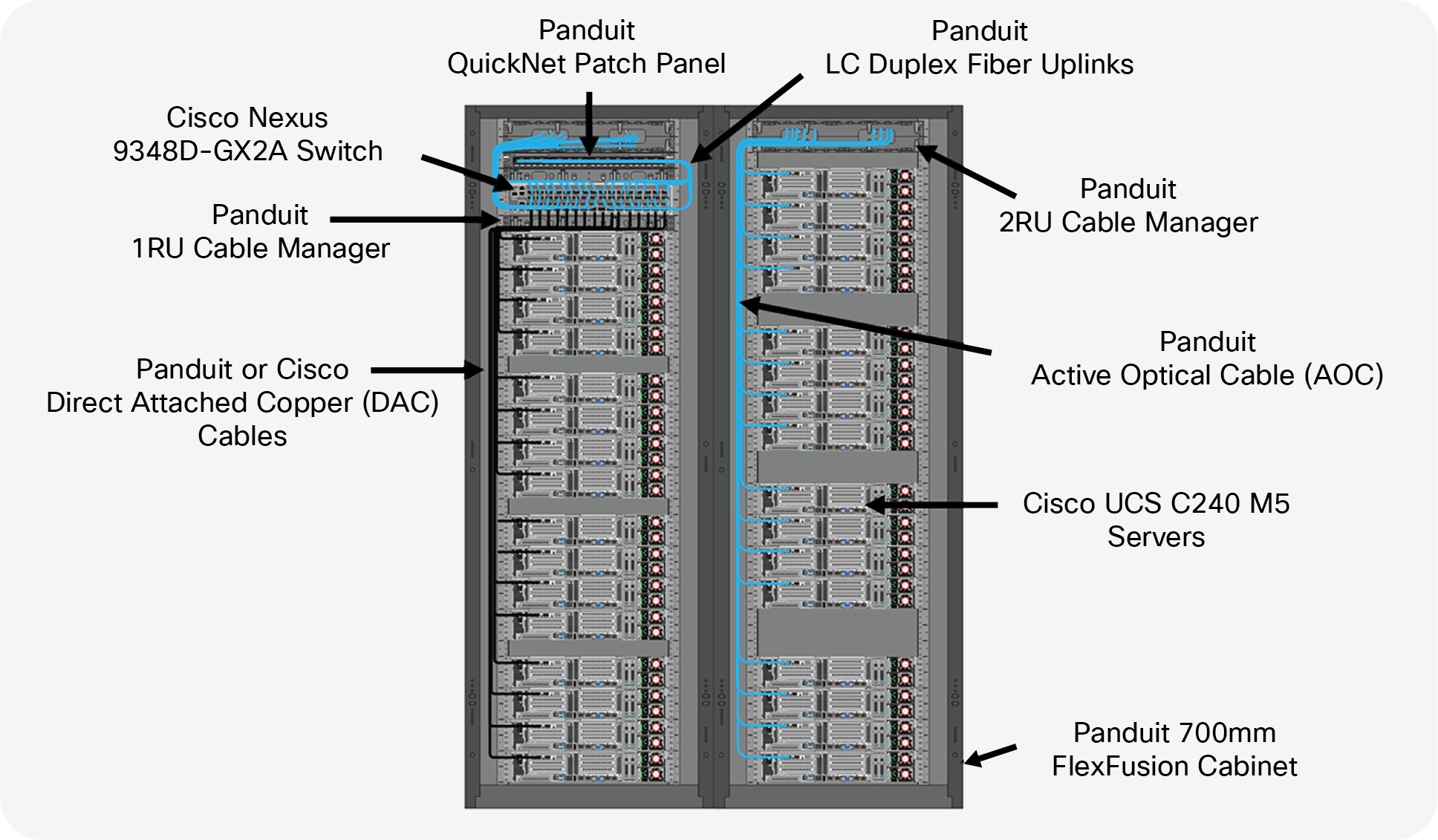
Two-cabinet POD with 16 servers each—(16) ports of 100G achieved by using (16) ports of 100G DACs, (16) ports of 100G AOCS, and (16) ports of 100G fiber uplinks for a 2:1 oversubscription.
Table 13. Cisco Nexus 9300-GX2A switch
| Switch |
Description |
| Nexus N9K-C9348D-GX2A |
Nexus 9300 48 ports 400G Switch, MACsec Capable |
Table 14. Cisco UCS C240 M5 Rack Server
| Server |
Description |
| UCSC-C240-M5SX: |
Cisco UCS C240 M5 24 SFF + 2 rear drives w/o CPU, mem, HD, PCIe, PS |
Table 15. Cisco 40/100 Gbps Network Interface Cards
| Network Interface Card |
Description |
| UCSC-PCIE-C100-04 |
Cisco UCS VIC 1495 2x 40/100G QSFP28 PCIe for C220 M5/M6, C240 M5/M6 |
| UCSC-MLOM-C100-04 |
Cisco UCS VIC 1495 2x 40/100G QSFP28 mLOM for C220 M5, C240 M5 |
| UCSC-P-M5S100GF |
MELLANOX CX-5 MCX515A-CCAT 1x100GbE QSFP PCIe NIC |
| UCSC-P-M5D100GF |
MELLANOX CX-5 MCX516A-CDAT 2x100GbE QSFP PCIe NIC |
| UCSC-P-I8D100GF |
Intel E810CQDA2 2x100 GbE QSFP28 PCIe NIC |
Source: https://tmgmatrix.cisco.com/
Table 16. Cisco 100 Gbps and 100G to 25 Gbps copper breakout cable
| 100G Copper Cables |
Description |
| QSFP-100G-CU1M |
100GBASE-CR4 Passive Copper Cable, 1m |
| QSFP-4SFP25G-CU2M |
100GBASE-CR4 Passive Copper Cable, 2m |
| QSFP-4SFP25G-CU3M |
100GBASE-CR4 Passive Copper Cable, 3m |
Table 17. Cisco 40/100 Gbps Bi-Directional Transceiver
| Pluggable Transceivers |
Description |
| QSFP-40/100G-SRBD |
Cisco 100GBase SR4 QSFP Transceiver, LC Duplex, 100m over OM4/5 |
Table 18. Panduit Direct attach copper cables, Active optical cables with Fiber and Cabinet Connectivity
| SKU |
Description |
|
|
Direct Attached Copper Cables 100G |
| PQSF2PXA1MBL |
QSFP28 100G Direct Attach Copper Cable Assembly, 30 AWG, Black, 1m |
| PQSF2PXA2MBL |
QSFP28 100G Direct Attach Copper Cable Assembly, 30 AWG, Black, 2m |
| PQSF2PXA3MBL |
QSFP28 100G Direct Attach Copper Cable Assembly, 30 AWG, Black, 3m |
|
|
Active Optical Cables 100G |
| AZ83NQ2Q2AQM*** |
Active Optical Cable Assembly, 100G QSFP28, OM4, Aqua, various lengths |
|
|
Cabinet and Fiber Connectivity |
| QPP24BL |
QuickNet 24-port Patch Panel |
| FZTRP7N7NYNF003 |
OM4 12 fiber PanMPO Interconnect, Female to Female, Method B, 3ft |
| FQMAP46CG |
Fiber Optic Migration Adapter Panel - 4 MPO Adapters – Type B |
| XG74222BS0001 |
Panduit FlexFusion Cabinet 700mm 42RU 1200mm deep |
| CMPH1 |
Panduit Cable Manager 1 RU |
| NM2 |
Panduit NetManager® Horizontal Cable Manger, 2RU |
The rise of 400-Gbps and 100-Gbps technologies is changing the data center landscape—from higher I/O bandwidth in the compute nodes to higher server uplink speeds and increasingly more powerful switch ASICs, all of which work together to keep pace with bandwidth demands. These network components not only impact the switch-and-compute infrastructure, but also become the deciding factor when choosing optical and copper interconnects as well as the overall cabling infrastructure design. In this white paper, we discuss the market trends, the impact in the cabling design, and practical deployment guidelines to help operators deploy high-speed server connectivity in the data centers.
For more information about compatibility, including optics/cables to platforms and optics to optics, visit: https://tmgmatrix.cisco.com/
https://tmgmatrix.cisco.com/iop
For other Panduit/Cisco-related resources, visit: www.panduit.com/panduitciscoalliance