Understanding the Differences Between OM4 and OM5 Multimode Fiber
Available Languages
Bias-Free Language
The documentation set for this product strives to use bias-free language. For the purposes of this documentation set, bias-free is defined as language that does not imply discrimination based on age, disability, gender, racial identity, ethnic identity, sexual orientation, socioeconomic status, and intersectionality. Exceptions may be present in the documentation due to language that is hardcoded in the user interfaces of the product software, language used based on RFP documentation, or language that is used by a referenced third-party product. Learn more about how Cisco is using Inclusive Language.
Multimode fiber is a staple of fiber-optic cable infrastructure in data centers and campus networks. The ISO/IEC 11801 standard defines five classes of multimode fiber: OM1, OM2, OM3, OM4 and OM5. In this white paper, we will review the basics of multimode fiber and the evolution of the different fiber standards. We’ll discuss the differences between OM4 and OM5 and clear up the misconceptions, discussing when OM5 is an appropriate choice and when OM4 will work just fine.
From a geometric optics perspective, light propagates down the core of an optical fiber as a result of total internal reflection caused by the index mismatch between the core and cladding (see figure 1). The diameter of the core defines the cone of acceptance-the angles at which light launched into the fiber can continue to propagate. If the angle of incidence ɵI is larger than the angle of acceptance ɵA, light will not propagate.
When a pulse of light is launched into a fiber, it propagates as a collection of spatial modes (as defined by wave theory, which is a more rigorous treatment outside the scope of this white paper). These spatial modes can be thought of as the electromagnetic equivalent of the vibrational modes of a drum head. Single-mode fiber is fabricated with a very narrow core that can only support the propagation of one mode, known as the fundamental mode. Multimode fiber has a core diameter that is large with respect to the operating wavelength of the incident light. The larger the core diameter, the more modes, or standing-wave patterns of light, that it can support.
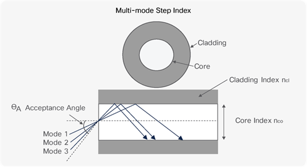
Light propagates through an optical fiber via total internal reflection from the refractive index mismatch between the cladding and the core. The larger the incident angle ɵI, the greater the number of reflections and the longer the time required to transit the fiber.
Modes that contain more energy closer to the center of the fiber are called lower-order modes and modes with energy closer to the cladding are called higher-order modes. Light launched into the fiber core at a greater incident angle (a higher-order mode) will travel a longer path and hence take more time to transit the fiber than light with a smaller incident angle (a lower-order mode). This variation in time of flight, also known as modal dispersion, leads to pulse widening. Modal dispersion in a fiber can cause intersymbol interference in the presence of noise and, potentially, transmission errors. Ultimately, modal dispersion reduces the fiber’s light-carrying capacity, or bandwidth.
Fiber evolution
Multimode fibers were the first fibers to be commercialized in the 1970s. Initially, multimode fibers were used with Light-Emitting Diode (LED) sources. Continuing multimode fiber development has led to improvements in bandwidth. Along with improved light sources such as Vertical-Cavity Surface-Emitting Lasers (VCSELs), which can be modulated at higher rates, these advances have enabled multimode fiber networks to achieve multi-gigabit data rates.
The first fibers to be developed were step-index silica multimode fibers, in which the index of refraction is constant across the width of the fiber core (see figure 2). In step-index fibers, any light that is launched within the acceptance angle is captured and guided within the fiber. The drawback is that step-index fiber supports a high number of modes and, hence, introduces large amounts of modal dispersion.
To reduce modal dispersion, researchers developed graded-index multimode fibers. In a graded-index fiber, the index of refraction varies parabolically across the width of the fiber core. The velocity of light in a material vM is given by
![]()
where c is the speed of light in a vacuum and nM is the refractive index of the material. Graded-index fiber is fabricated with a higher index in the center to retard the faster modes, decreasing modal dispersion.
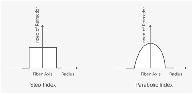
In step-index multimode fiber (left), the refractive index of the core is constant across its width. In graded-index multimode fiber (right), the index of refraction varies parabolically across the cross-section of the fiber.
Fiber classification
In the commercial sphere, multimode fibers are classified by their modal bandwidths. Recall the fiber classes defined by ISO/IEC 11801: OM1, OM2, OM3, OM4 and OM5. In the case of OM1 and OM2, the standard defines specifications for core diameters of both 50 µm and 62.5 µm, while the OM3, OM4 and OM5 specifications are built around a core diameter of 50 µm only.
The advent of VCSELS in the late 90s, with their ability to sustain high modulation rates, pushed fiber manufacturers to improve their fiber bandwidths to take advantage of this new source. The result was OM3, a new class of 50-µm-core multimode fiber capable of supporting 10 Gb/s transmission. The OM3 standard was published in 2002 and is closely linked to the IEEE 802.3 10GbE Ethernet standard, also released in 2002. OM3 supports 10 Gb/s speeds over links of up to 300 m.
After the introduction of OM3 fiber, manufacturers worked toward a higher grade of fiber, Laser-Optimized Multimode Fiber (LO-MMF), with tighter specifications. The result was OM4, which has an overfilled launch (OFL) bandwidth of 3500 at 850 nm (more about that later). OM4 enables 10 Gb/s operation over distances of up to 400 m. Alternatively, it supports point-to-point 40 Gb/s and 100 Gb/s Ethernet links of four or 10 pairs of fibers across distances of up to 150 m.
The release of OM5 generated keen interest in the user community. Unfortunately, it has also led to misconceptions about the relative performance of OM4 and OM5, and when to use each. To clear up these misunderstandings, we need to first review the test and measurement techniques used to characterize multimode fiber performance.
Overfilled launch condition
LEDs, the sources initially used with multimode fiber, excite all the possible modes in the fiber. For testing, the OFL condition emulates an LED quite well by uniformly exciting all guided modes in the fiber. OM1 and OM2 fibers were defined with OFL bandwidth, as they were initially developed for use with LED light sources.
We measure OFL bandwidth using a mode scrambler between a laser and the fiber to provide a spatially, angularly and uniformly over-filled launch. The OFL bandwidth is then measured by injecting a short pulse of light into the fiber and measuring its temporal response. The data from the input pulse and output pulses are Fourier transformed to convert from time to frequency domain, then the frequency is solved for at the half-power point. That frequency is the bandwidth. The result is normalized by the length and expressed as the bandwidth-length product in units of MHz.km (see table 1).
Table 1. OFL modal bandwidth
| Fiber Class |
Core Diameter (um) |
OFL-BW at 850nm (MHz.km) |
OFL-BW at 1300nm (MHz.km) |
| OM1 |
50 and 62.5 |
>200 |
>500 |
| OM2 |
50 and 62.5 |
>500 |
>500 |
| OM3 |
50 only |
>1500 |
>500 |
| OM4 |
50 only |
>3500 |
>500 |
| OM5 |
50 only |
>3500 |
>500 |
Effective Modal Bandwidth (EMB)
OFL bandwidth does a good job of emulating the launch conditions of an LED light source, but it is not representative of a VCSEL. A VCSEL has a much narrower beam angle than an LED and excites a smaller number of possible modes within the fiber. Additionally, VCSELs vary in launch conditions significantly from one another. For modern multimode fibers designed for use with VCSELs, we define fiber capacity using the Effective Modal Bandwidth (EMB).
EMB is the frequency-length product and therefore it is defined as for a specific length of fiber at a specific measurement wavelength, expressed in units of MHz.km. Due to the large number of VCSEL patterns, no standardized launch conditions have been defined. There are strategies to characterize fiber performance with VCSELs, however. EMB is a calculated metric that is dependent on Differential Mode Delay (DMD) and the output of the laser.
DMD measurement is a way of characterizing the modal properties of multimode fibers. There are so many modes the light can traverse, that we group the modes into mode groups. The difference in mode-group delays is defined as DMD. DMD is a quantification of modal dispersion, as it defines the time delay for modes in specific areas of the fiber.
DMD measurement involves using a single-mode fiber to inject a short pulse of light into the multimode fiber in steps across the radius of the multimode fiber. The position of the single-mode fiber with respect to the center of the multimode fiber is called the offset launch. The time each of these pulses takes to traverse a length of fiber is plotted against its offset launch. This plot is the DMD plot and details how quickly higher-order modes are moving with respect to lower-order modes (see figure 3). A large difference between the two indicates large dispersion.
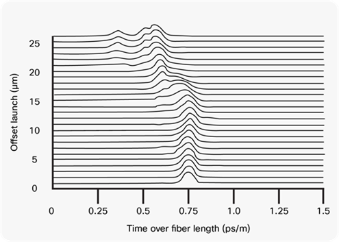
Plot of Differential Mode Delay (DMD) for a 50-μm-core fiber shows a fiber with a significant difference between higher- and lower-order modes.
The DMD values are defined in the standards to allow for a minimum EMB value. The standards also propose an alternative to DMD values: the EMBc, computed effective modal bandwidth, which has been defined to evaluate the worst EMB the fiber may exhibit when coupled to a VCSEL. IEC 11801 specifies EMB values for OM3, OM4 and OM5, as these fibers were developed for use with VCSELs (see table 2).
Table 2. ISO/IEC 11801 Equilibrium Modal Bandwidth (EMB) specification
|
|
|
EMB (MHz.km) |
|
| Fiber Type |
Core Size (µm) |
850 nm |
953 nm |
| OM3 |
50 |
2000 |
|
| OM4 |
50 |
4700 |
|
| OM5 |
50 |
4700 |
2470 |
OM5 vs. OM4
Now that we've put everything in context, we can compare OM4 and OM5 and clear up those misconceptions. Let’s start with performance. Recall that EMB is defined for a specific length of fiber at a specific measurement wavelength and that it varies with wavelength. The TIA standard for OM4 only mandates a bandwidth of 4700 MHz.km at the 850-nm measurement wavelength. At other wavelengths, there is no established specification for EMB; therefore, EMB varies widely at non-850-nm wavelengths among different commercially available OM4 fibers.
In contrast, OM5 has a requirement of 4700 MHz.km at 850 nm, but also has a requirement for 2470 MHz.km at 953 nm. This additional requirement ensures that all OM5 fibers will meet that minimum performance requirement at 953 nm.
There have been many claims that OM5 has better reach than OM4. That’s not necessarily true. Only multi-wavelength transceivers with operating wavelengths that include longer wavelengths like 940 nm can leverage the reach advantage of OM5. Since OM5 has a required minimum EMB at 953 nm, all OM5 fibers have a guaranteed minimum reach at the longer wavelengths. Because the OM4 specification does not include an EMB requirement at the longer wavelengths, the bandwidth at these wavelengths is uncontrolled. It could be worse than OM5-or it could be better. There’s simply no way to know.
Does that mean OM5 is the better option? Not necessarily. It is only for multi-wavelength transceivers operating across the waveband from 850 nm to 940 nm that OM5 delivers a meaningful performance improvement compared to OM4. In these cases, the cost increase is worthwhile. The vast majority of multimode transceivers operate only at 850 nm, however. In these cases, there is no reach benefit for OM5 compared to OM4.
Cisco support of OM5
Most of Cisco’s multimode transceivers are single-wavelength devices operating at 850 nm; therefore, there is no difference in reach for these transceivers whether OM5 or OM4 is used. BiDi uses two wavelengths and similarly the wavelength range does not expose it to significant benefits from OM5.
The Cisco QSFP-40G-CSR4 has four lanes and operates over four wavelengths (850, 880, 910 and 940 nm). This module does benefit from the improved bandwidth of OM5 and therefore has a reach of 440 m on OM5 vs 400 m on OM4.
It’s an engineering truism that there’s no perfect solution, just the best solution for the application at hand. OM5 cable is not intrinsically better than OM4 cable. OM5 only delivers increased reach for transceivers with lanes operating at 940 nm. For conventional multimode transceivers operating at 850 nm alone, OM4 provides a cost-effective solution.
Further reading
Fiber Optics Part 3: Fiber Dispersion Will Change The Way You See Your Links