Cisco Industrial Temperature 10GBASE Dense Wavelength-Division Multiplexing SFP+ Modules Data Sheet
Available Languages
Bias-Free Language
The documentation set for this product strives to use bias-free language. For the purposes of this documentation set, bias-free is defined as language that does not imply discrimination based on age, disability, gender, racial identity, ethnic identity, sexual orientation, socioeconomic status, and intersectionality. Exceptions may be present in the documentation due to language that is hardcoded in the user interfaces of the product software, language used based on RFP documentation, or language that is used by a referenced third-party product. Learn more about how Cisco is using Inclusive Language.
Use industrial temperature (iTemp) Dense Wavelength-Division Multiplexing (DWDM) SFP+ modules to integrate baseband digital DWDM transport into your R-PHY shelf blades, RPDs, or digital PICs.
The Cisco® iTemp 10GBASE DWDM SFP+ Modules (Figure 1) are pluggable, temperature-hardened transceiver modules designed to deliver Remote PHY (R-PHY) capability in field or headend environments. They enable plug-and-play configuration of 10-Gbps Ethernet signals for simple configuration of R-PHY devices or shelves. There are 2 types of 10GBASE DWDM SFP+ modules, one tunable module and 3 reaches of fixed wavelength modules. The fixed wavelength modules have With 40 ITU C-band wavelengths and three different distance values available. The tunable module has 70km reach, and 96 50Ghz ITU C-band wavelengths it can be tuned to. Operators can control cost and wavelength assignments, and match link budgets in their fiber-deep networks. The standards-based SFP+ devices are compatible with existing passive filters and splitters, speeding deployments and minimizing service disruptions.
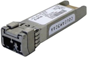
Cisco DWDM SFP+ Module
The Cisco iTemp 10GBASE Dense Wavelength-Division Multiplexing SFP+ Fixed Wavelength Modules offers the following features and benefits:
● Supports 10-Gigabit LAN PHY data rates (10.3125 Gbps) for IEEE Ethernet compatibility.
● Industrial temperature range of operation from -40°C to 85°C
● Hot-swappable transceiver plugs into remote PHY devices, converged broadband-8 (cBR-8) Digital Physical Interface Card (D-PIC), and a variety of Cisco switches or routers in common usage.
● Support for a pay-as-you-grow model for investment protection.
● Standard digital diagnostics capability for incorporation into network management systems.
● Multi-Source Agreement (MSA)-compliant physical form factor for compatibility with a broad range of available products.
● DWDM fixed-wavelength modules support International Telecommunication Union (ITU) 100-GHz spaced channels (ITU 20—ITU 59)Dispersion-tolerant link lengths without added dispersion compensation; up to 80 km supported.
● Supports the Cisco Quality Identification (ID) feature, enabling a Cisco switch or router to identify that the SFP+ module is tested and certified by Cisco.
The Cisco iTemp 10GBASE Dense Wavelength-Division Multiplexing SFP+ Tunable Module, DWDM-SFP10G-C-I offers the following features and benefits
● The DWDM-SFP10G-C-I has a limiting electrical interface receiver, which does not require EDC PHY on the host board.
● The DWDM-SFP10G-C-I can be plugged into any SFP+ port.
● DWDM tunable wavelength module supports 96 tunable ITU 50Ghz spaced channels.
● Reach of 70km, assuming fiber chromatic dispersion of 20ps/(nm*km).
● Tunability enables minized inventory and simplified, rapid deployment.
Tables 1 through 3 describe the transmission and receiver characteristics in a 20 km link, with RPHY-S10G-20K-XXX fixed wavelength modules
Table 1. 20-km transmitter characteristics
| Description |
Unit |
Minimum |
Typical |
Maximum |
Notes |
| Launch power |
dBm |
-1 |
|
+3 |
|
| Extinction ratio |
dB |
7.5 |
|
|
|
| Wavelength λi |
nm |
1530.33 |
|
1561.42 |
ITU-20 to 59 |
| Channel spacing |
GHz |
|
100 |
|
At End Of Life (EOL) over operating voltage and temperatures |
| Wavelength stability (after startup) |
pm |
λi-100 |
|
λi+100 |
|
| Side Mode Suppression Ratio (SMSR) |
dB |
30 |
|
|
|
| Crossing point |
% |
40 |
|
50 |
|
| Eye mask |
% |
10 |
|
|
|
| Maximum spectral width |
pm |
|
|
200 |
Modulated, full width, at -20dB, with RBW=0.01nm |
Table 2. 20-km receiver characteristics
| Description |
Unit |
Minimum |
Maximum |
Notes |
| Receiver wavelength range |
nm |
1529 |
1562 |
Covers ITU-20 to ITU-59 |
| Receiver reflectance |
dB |
|
-27 |
|
| Maximum receiver input power |
dBm |
+3 |
|
Damage threshold |
Table 3. 20-km link performance – no FEC application (10 GE LAN)
| Condition |
OSNR@0.5nm RBW (dB) |
Receiver power range (dBm) |
Notes |
||
|
|
Min |
Max |
Min |
Max |
|
| Power-limited link |
|||||
| Back to back |
25 |
|
-15 |
-1 |
At BER=1E-12, PRBS31, and 10 GE frame |
| Dispersion-limited link |
|||||
| -200 ps/nm to 400 ps/nm |
25 |
|
-14 |
-1 |
At BER=1E-12, PRBS31, and 10 GE frame |
Tables 4 through 6 describe the transmission and receiver characteristics and link performance at 40 km with RPHY-S10G-40K-XXX fixed wavelength modules
Table 4. 40-km transmitter characteristics
| Description |
Unit |
Min |
Typical |
Max |
Notes |
| Launch power |
dBm |
-1 |
|
+3 |
|
| Extinction ratio |
dB |
8.2 |
|
|
|
| Wavelength λi |
nm |
1530.33 |
|
1561.42 |
ITU-20 to ITU-59 |
| Channel spacing |
GHz |
|
100 |
|
At EOL over operating voltage and temperatures |
| Wavelength stability (after startup) |
pm |
λi-100 |
|
λi+100 |
|
| SMSR |
dB |
30 |
|
|
|
| Crossing point |
% |
40 |
|
50 |
|
| Eye mask |
% |
10 |
|
|
|
| Maximum spectral width |
pm |
|
|
200 |
Modulated, full width, at -20dB, with RBW=0.01nm |
Table 5. 40-km receiver characteristics
| Description |
Unit |
Min |
Max |
Notes |
| Receiver wavelength range |
nm |
1529 |
1562 |
Covers ITU-20 to ITU-59 |
| Receiver reflectance |
dB |
|
-27 |
|
| Maximum receiver input power |
dBm |
+3 |
|
Damage threshold |
Table 6. 40-km link performance – no FEC application (10 GE LAN)
| Condition |
OSNR@0.5nm RBW (dB) |
Receiver power range (dBm) |
Notes |
||||
|
|
Min |
Max |
Min |
Max |
|
||
| Power-limited link |
|||||||
| Back to back |
25 |
|
-23 |
-7 |
At BER=1E-12, PRBS31, and 10 GE frame |
||
| Dispersion-limited link |
|||||||
| -400 ps/nm to 800 ps/nm |
25 |
|
-21 |
-7 |
At BER=1E-12, PRBS31, and 10 GE frame |
||
Tables 7 through 9 describe the transmission and receiver characteristics and link performance at 80 km with RPHY-S10G-80K-XXX fixed wavelength modules
Table 7. 80-km transmitter characteristics
| Description |
Unit |
Min |
Typical |
Max |
Notes |
| Launch power (Limiting) |
dBm |
0 |
1 |
3 |
|
| Extinction ratio (Limiting) |
dB |
8.2 |
|
|
|
| Wavelength λi |
nm |
1530.33 |
|
1561.42 |
ITU-20 to ITU-59 |
| Channel spacing |
GHz |
|
100 |
|
At EOL over operating voltage and temperatures |
| Wavelength stability (after startup) |
pm |
λi-100 |
|
λi+100 |
|
| SMSR |
dB |
30 |
|
|
|
| Crossing point |
% |
40 |
|
50 |
|
| Eye mask |
% |
10 |
|
|
|
| Maximum spectral width |
pm |
|
|
200 |
Modulated, full width, at -20dB, with RBW=0.01nm |
| SBS threshold (limiting) |
dBm |
+6 |
|
|
|
Table 8. 80-km receiver characteristics
| Description |
Unit |
Min |
Max |
Notes |
| Receiver wavelength range |
nm |
1529 |
1562 |
Covers ITU-20 to ITU-59 |
| Receiver reflectance |
dB |
|
-27 |
|
| Maximum receiver input power |
dBm |
+3 |
|
Damage threshold |
Table 9. 80-km link performance – no FEC application (10 GE LAN)
| Condition |
OSNR@0.5nm RBW (dB) |
Receiver power range (dBm) |
Notes |
||||
|
|
Min |
Max |
Min |
Max |
|
||
| Power-limited link (limiting) |
|||||||
| Back to back |
28 |
|
-23.5 |
-7 |
At BER=1E-12, PRBS31, and 10 GE frame |
||
| Dispersion-limited link |
|||||||
| -500 ps/nm to 1400 ps/nm |
28 |
|
-21.1 |
-7 |
At BER=1E-12, PRBS31, and 10 GE frame |
||
Notes:
1. Receiver optical filter bandwidth @-3dB for BER measurement shall be 0.4 nm.
Tables 10 through 11 describe the transmitter and receiver characteristics of DWDM-SFP10G-C-I Tunable Module.
Table 10. Optical Parameters for Tunable limiting electrical interface DWDM SFP+, DWDM-SFP10G-C-I.
| Parameter |
Symbol |
Minimum |
Typical |
Maximum |
Units |
Notes and Conditions |
| Transmitter |
||||||
| Spectral width |
|
|
|
0.5 |
nm |
Full width, -20 dB from maximum, with Resolution Bandwidth (RBW) = 0.01 nm |
| Transmitter wavelength stability after startup |
|
x - 20 |
x |
x + 20 |
pm |
Refer to Table 11 for center wavelengths |
| Side-mode suppression ratio |
SMSR |
35 |
|
|
dB |
|
| Transmitter extinction ratio |
|
9 |
|
|
dB |
|
| Transmitter optical output power |
Pout |
-1 |
|
3.0 |
dBm |
Average power coupled into single-mode fiber |
| Stimulated Brillouin Scattering (SBS) Threshold |
|
10 |
|
|
dBm |
|
| Receiver |
||||||
| Receiver optical input wavelength |
|
1525 |
|
1570 |
nm |
|
| Receiver damage threshold |
|
5.0 |
|
|
dBm |
|
| Receiver overload |
|
-7.0 |
|
|
dBm |
|
| Receiver Power Performance |
||||||
|
|
Units |
Range |
Notes and Conditions |
|||
| Performance at 10G LAN (NO-FEC Application) |
||||||
| Input power range |
dBm |
-7 to -24 |
At BER=1E-12, back-to-back, unamplified link |
|||
| Input power range (dispersion-limited) |
dBm |
-7 to -21 |
At BER=1E-12, -300 to 1400 ps/nm chromatic dispersion, unamplified link |
|||
| Noise Limited Back to back1 |
dBm |
-10 to -20 |
At BER=1E-12, -300 to, amplified link with min 19dB OSNR (0.5nm RBW) |
|||
| Noise Limited Back to back 2 |
dBm |
-7 to -18 |
At BER=1E-12, amplified link with min 17.5dB OSNR (0.5nm RBW) |
|||
| Input power range (dispersion- and noise-limited) |
dBm |
-7 to -17 |
At BER=1E-12, -300 to 1400 ps/nm chromatic dispersion, amplified link with min 19dB OSNR (0.5nm RBW) |
|||
Table 11 shows the 96 DWDM ITU-50GHz channels to which the DWDM-SFP10G-C-I device can be tuned.
Table 11. ITU 50-GHz Center Wavelengths and Channel Numbering for DWDM-SFP10G-C-I
| Channel ID |
Frequency (THz) |
Wavelength (nm) |
Channel ID |
Frequency (THz) |
Wavelength (nm) |
| 1 |
191.35 |
1566.72 |
49 |
193.75 |
1547.32 |
| 2 |
191.4 |
1566.31 |
50 |
193.8 |
1546.92 |
| 3 |
191.45 |
1565.90 |
51 |
193.85 |
1546.52 |
| 4 |
191.5 |
1565.50 |
52 |
193.9 |
1546.12 |
| 5 |
191.55 |
1565.09 |
53 |
193.95 |
1545.72 |
| 6 |
191.6 |
1564.68 |
54 |
194 |
1545.32 |
| 7 |
191.65 |
1564.27 |
55 |
194.05 |
1544.92 |
| 8 |
191.7 |
1563.86 |
56 |
194.1 |
1544.53 |
| 9 |
191.75 |
1563.45 |
57 |
194.15 |
1544.13 |
| 10 |
191.8 |
1563.05 |
58 |
194.2 |
1543.73 |
| 11 |
191.85 |
1562.64 |
59 |
194.25 |
1543.33 |
| 12 |
191.9 |
1562.23 |
60 |
194.3 |
1542.94 |
| 13 |
191.95 |
1561.83 |
61 |
194.35 |
1542.54 |
| 14 |
192 |
1561.42 |
62 |
194.4 |
1542.14 |
| 15 |
192.05 |
1561.01 |
63 |
194.45 |
1541.75 |
| 16 |
192.1 |
1560.61 |
64 |
194.5 |
1541.35 |
| 17 |
192.15 |
1560.20 |
65 |
194.55 |
1540.95 |
| 18 |
192.2 |
1559.79 |
66 |
194.6 |
1540.56 |
| 19 |
192.25 |
1559.39 |
67 |
194.65 |
1540.16 |
| 20 |
192.3 |
1558.98 |
68 |
194.7 |
1539.77 |
| 21 |
192.35 |
1558.58 |
69 |
194.75 |
1539.37 |
| 22 |
192.4 |
1558.17 |
70 |
194.8 |
1538.98 |
| 23 |
192.45 |
1557.77 |
71 |
194.85 |
1538.58 |
| 24 |
192.5 |
1557.36 |
72 |
194.9 |
1538.19 |
| 25 |
192.55 |
1556.96 |
73 |
194.95 |
1537.79 |
| 26 |
192.6 |
1556.55 |
74 |
195 |
1537.40 |
| 27 |
192.65 |
1556.15 |
75 |
195.05 |
1537.00 |
| 28 |
192.7 |
1555.75 |
76 |
195.1 |
1536.61 |
| 29 |
192.75 |
1555.34 |
77 |
195.15 |
1536.22 |
| 30 |
192.8 |
1554.94 |
78 |
195.2 |
1535.82 |
| 31 |
192.85 |
1554.54 |
79 |
195.25 |
1535.43 |
| 32 |
192.9 |
1554.13 |
80 |
195.3 |
1535.04 |
| 33 |
192.95 |
1553.73 |
81 |
195.35 |
1534.64 |
| 34 |
193 |
1553.33 |
82 |
195.4 |
1534.25 |
| 35 |
193.05 |
1552.93 |
83 |
195.45 |
1533.86 |
| 36 |
193.1 |
1552.52 |
84 |
195.5 |
1533.47 |
| 37 |
193.15 |
1552.12 |
85 |
195.55 |
1533.07 |
| 38 |
193.2 |
1551.72 |
86 |
195.6 |
1532.68 |
| 39 |
193.25 |
1551.32 |
87 |
195.65 |
1532.29 |
| 40 |
193.3 |
1550.92 |
88 |
195.7 |
1531.90 |
| 41 |
193.35 |
1550.52 |
89 |
195.75 |
1531.51 |
| 42 |
193.4 |
1550.12 |
90 |
195.8 |
1531.12 |
| 43 |
193.45 |
1549.72 |
91 |
195.85 |
1530.72 |
| 44 |
193.5 |
1549.32 |
92 |
195.9 |
1530.33 |
| 45 |
193.55 |
1548.91 |
93 |
195.95 |
1529.94 |
| 46 |
193.6 |
1548.51 |
94 |
196 |
1529.55 |
| 47 |
193.65 |
1548.11 |
95 |
196.05 |
1529.16 |
| 48 |
193.7 |
1547.72 |
96 |
196.1 |
1528.77 |
Physical and environmental characteristics
● Dimensions (H x W x D): 8.5 x 13.4 x 56.5 mm.
● Cisco SFP+ modules typically weigh 75 grams or less.
● Industrial operational case temperature range (IND): -40 to 85°C (-40 to 185°F).
● Storage temperature range: -40 to 85°C (-40 to 185°F).
● Optical connector is Duplex LC/PC.
● Bail color: 80/70 km - green, 40 km - red, 20 km – white.
● The maximum power consumption of DWDM-SFP10G-C-I is 2.3W.
Regulatory, safety, and standards compliance
● SFP+ MSA SFF-8431 (electrical).
● SFF-8432 improved pluggable form factor (mechanical).
● SFF-8472 diagnostic monitor interface for optical transceiver.
● IEEE 802.3: 10-Gigabit Ethernet.
● laser class 1 (21CFR1040 and IEC 60825).
● Standard warranty: 1 year.
● Expedited replacement available via a Cisco SMARTnet® Service support contract.
Table 12. Cisco iTemp 10GBASE DWDM SFP+ Fixed Wavelength Modules product identification listing
| ITU |
20-km parts |
40-km parts |
80-km parts |
| 20 |
RPHY-S10G-20K-200= |
RPHY-S10G-40K-200= |
RPHY-S10G-80K-200= |
| 21 |
RPHY-S10G-20K-210= |
RPHY-S10G-40K-210= |
RPHY-S10G-80K-210= |
| 22 |
RPHY-S10G-20K-220= |
RPHY-S10G-40K-220= |
RPHY-S10G-80K-220= |
| 23 |
RPHY-S10G-20K-230= |
RPHY-S10G-40K-230= |
RPHY-S10G-80K-230= |
| 24 |
RPHY-S10G-20K-240= |
RPHY-S10G-40K-240= |
RPHY-S10G-80K-240= |
| 25 |
RPHY-S10G-20K-250= |
RPHY-S10G-40K-250= |
RPHY-S10G-80K-250= |
| 26 |
RPHY-S10G-20K-260= |
RPHY-S10G-40K-260= |
RPHY-S10G-80K-260= |
| 27 |
RPHY-S10G-20K-270= |
RPHY-S10G-40K-270= |
RPHY-S10G-80K-270= |
| 28 |
RPHY-S10G-20K-280= |
RPHY-S10G-40K-280= |
RPHY-S10G-80K-280= |
| 29 |
RPHY-S10G-20K-290= |
RPHY-S10G-40K-290= |
RPHY-S10G-80K-290= |
| 30 |
RPHY-S10G-20K-300= |
RPHY-S10G-40K-300= |
RPHY-S10G-80K-300= |
| 31 |
RPHY-S10G-20K-310= |
RPHY-S10G-40K-310= |
RPHY-S10G-80K-310= |
| 32 |
RPHY-S10G-20K-320= |
RPHY-S10G-40K-320= |
RPHY-S10G-80K-320= |
| 33 |
RPHY-S10G-20K-330= |
RPHY-S10G-40K-330= |
RPHY-S10G-80K-330= |
| 34 |
RPHY-S10G-20K-340= |
RPHY-S10G-40K-340= |
RPHY-S10G-80K-340= |
| 35 |
RPHY-S10G-20K-350= |
RPHY-S10G-40K-350= |
RPHY-S10G-80K-350= |
| 36 |
RPHY-S10G-20K-360= |
RPHY-S10G-40K-360= |
RPHY-S10G-80K-360= |
| 37 |
RPHY-S10G-20K-370= |
RPHY-S10G-40K-370= |
RPHY-S10G-80K-370= |
| 38 |
RPHY-S10G-20K-380= |
RPHY-S10G-40K-380= |
RPHY-S10G-80K-380= |
| 39 |
RPHY-S10G-20K-390= |
RPHY-S10G-40K-390= |
RPHY-S10G-80K-390= |
| 40 |
RPHY-S10G-20K-400= |
RPHY-S10G-40K-400= |
RPHY-S10G-80K-400= |
| 41 |
RPHY-S10G-20K-410= |
RPHY-S10G-40K-410= |
RPHY-S10G-80K-410= |
| 42 |
RPHY-S10G-20K-420= |
RPHY-S10G-40K-420= |
RPHY-S10G-80K-420= |
| 43 |
RPHY-S10G-20K-430= |
RPHY-S10G-40K-430= |
RPHY-S10G-80K-430= |
| 44 |
RPHY-S10G-20K-440= |
RPHY-S10G-40K-440= |
RPHY-S10G-80K-440= |
| 45 |
RPHY-S10G-20K-450= |
RPHY-S10G-40K-450= |
RPHY-S10G-80K-450= |
| 46 |
RPHY-S10G-20K-460= |
RPHY-S10G-40K-460= |
RPHY-S10G-80K-460= |
| 47 |
RPHY-S10G-20K-470= |
RPHY-S10G-40K-470= |
RPHY-S10G-80K-470= |
| 48 |
RPHY-S10G-20K-480= |
RPHY-S10G-40K-480= |
RPHY-S10G-80K-480= |
| 49 |
RPHY-S10G-20K-490= |
RPHY-S10G-40K-490= |
RPHY-S10G-80K-490= |
| 50 |
RPHY-S10G-20K-500= |
RPHY-S10G-40K-500= |
RPHY-S10G-80K-500= |
| 51 |
RPHY-S10G-20K-510= |
RPHY-S10G-40K-510= |
RPHY-S10G-80K-510= |
| 52 |
RPHY-S10G-20K-520= |
RPHY-S10G-40K-520= |
RPHY-S10G-80K-520= |
| 53 |
RPHY-S10G-20K-530= |
RPHY-S10G-40K-530= |
RPHY-S10G-80K-530= |
| 54 |
RPHY-S10G-20K-540= |
RPHY-S10G-40K-540= |
RPHY-S10G-80K-540= |
| 55 |
RPHY-S10G-20K-550= |
RPHY-S10G-40K-550= |
RPHY-S10G-80K-550= |
| 56 |
RPHY-S10G-20K-560= |
RPHY-S10G-40K-560= |
RPHY-S10G-80K-560= |
| 57 |
RPHY-S10G-20K-570= |
RPHY-S10G-40K-570= |
RPHY-S10G-80K-570= |
| 58 |
RPHY-S10G-20K-580= |
RPHY-S10G-40K-580= |
RPHY-S10G-80K-580= |
| 59 |
RPHY-S10G-20K-590= |
RPHY-S10G-40K-590= |
RPHY-S10G-80K-590= |
Table 13. Cisco iTemp 10GBASE DWDM SFP+ Tunable Wavelength ordering guide
| Product Number |
Description |
ITU Channel |
| DWDM-SFP10G-C-I= |
10GBASE-DWDM tunable SFP+, Limiting Interface 50Ghz ITU grid) |
See Table 11 |
Cisco environmental sustainability
Information about Cisco’s environmental sustainability policies and initiatives for our products, solutions, operations, and extended operations or supply chain is provided in the “Environment Sustainability” section of Cisco’s Corporate Social Responsibility (CSR) Report.
Reference links to information about key environmental sustainability topics (mentioned in the “Environment Sustainability” section of the CSR Report) are provided in the following table:
| Sustainability topic |
Reference |
| Information on product material content laws and regulations |
|
| Information on electronic waste laws and regulations, including products, batteries, and packaging |
Cisco makes the packaging data available for informational purposes only. It may not reflect the most current legal developments, and Cisco does not represent, warrant, or guarantee that it is complete, accurate, or up to date. This information is subject to change without notice.
Flexible payment solutions to help you achieve your objectives
Cisco Capital makes it easier to get the right technology to achieve your objectives, enable business transformation and help you stay competitive. We can help you reduce the total cost of ownership, conserve capital, and accelerate growth. In more than 100 countries, our flexible payment solutions can help you acquire hardware, software, services and complementary third-party equipment in easy, predictable payments. Learn more.
| New or revised topic |
Described In |
Date |
| New PID DWDM-SFP-10G-C-I added |
Table 13 Ordering guide |
October 18, 2023 |
| - |
- |
- |
| - |
- |
- |