Deploy a Cisco HyperFlex All-NVMe Hyperconverged Infrastructure Solution for SAP HANA
Available Languages
Bias-Free Language
The documentation set for this product strives to use bias-free language. For the purposes of this documentation set, bias-free is defined as language that does not imply discrimination based on age, disability, gender, racial identity, ethnic identity, sexual orientation, socioeconomic status, and intersectionality. Exceptions may be present in the documentation due to language that is hardcoded in the user interfaces of the product software, language used based on RFP documentation, or language that is used by a referenced third-party product. Learn more about how Cisco is using Inclusive Language.
This section provides a high-level view of the certified hyperconverged infrastructure (HCI) for SAP HANA using the Cisco HyperFlex™ All NVMe solution.
SAP landscapes frequently are deployed in virtualization environments. In recent years, SAP has been encouraging its customers to migrate to SAP’s own database platform of the future: SAP HANA. In the past, SAP HANA databases were deployable on virtual servers or on physical machines, and now they are allowed and certified to run on hyperconverged infrastructure.
With the launch of the Cisco HyperFlex system, Cisco offers a low-cost, easy-to-deploy, high-performance hyperconverged virtual server platform that is an excellent solution for both SAP HANA databases and SAP landscapes. You can use this Cisco HyperFlex solution to deploy SAP application servers, fully virtualized SAP HANA servers, and other non-HANA virtual servers on the same hyperconverged infrastructure.
This document describes how to deploy a single production SAP HANA virtual machine on a single node of a Cisco HyperFlex All-NVMe cluster with SUSE Linux Enterprise Server (SLES) for SAP 12 SP4 as the operating system. This document uses a four-node Cascade Lake–based Cisco HyperFlex cluster as an example, enabling the cluster to have eight production SAP HANA virtual machines.
Red Hat Enterprise Linux (RHEL) for SAP Applications also can be installed. This document does not cover this configuration.
This document does not cover the installation and configuration procedure for the Cisco HyperFlex HX Data Platform as this is not in the scope of this document.
The discussions in this document of the Cisco HyperFlex node are for informational purposes only.
The Cisco HyperFlex for SAP HANA solution offers the following benefits:
● Single hardware platform: The Cisco Unified Computing System™ (Cisco UCS®) is the base platform for Cisco HyperFlex systems, which provide a fully contained hyperconverged environment, combining networking, storage, and virtualization resources in a single system. You can deploy additional Cisco UCS servers alongside the Cisco HyperFlex solution in the same Cisco UCS domain to service other workloads.
● Simplified management: A single administrator can manage all aspects of Cisco UCS and the Cisco HyperFlex system through Cisco UCS Manager and the VMware vCenter Web Client, making tasks much easier and faster to complete.
● Rapid deployment: The programmability and ease of use of Cisco UCS Manager allow you to deploy Cisco HyperFlex systems quickly. These features also allow you to rapidly provision additional Cisco UCS servers for other workload requirements.
Customers who have already invested in Cisco® products and technologies have the opportunity to mitigate their risk further by deploying familiar and tested Cisco UCS technology.
Audience
The target audience for this document includes storage administrators, data center architects, database administrators, field consultants; IT managers, SAP solution architects, and customers who want to implement SAP HANA on the Cisco HyperFlex HCI solution. A working knowledge of SAP HANA Database, Linux, server, storage, and network technologies is assumed.
SAP has defined hardware and software requirements for running SAP HANA on hyperconverged infrastructure.
Although SAP allows the Cascade Lake CPU models (which have eight or more cores) listed in the SAP HANA Tailored Datacenter Integration (TDI) Phase V model to be used in HCI for SAP HANA, the Cisco HyperFlex configuration does not support all the CPU models. You must verify support for the CPU models used in the Cisco HyperFlex configuration before proceeding with the installation.
You also need to consider an important SAP limitation to socket use. The socket used by the storage controller virtual machine cannot be shared to run the production SAP HANA virtual machine. That is, the production SAP HANA virtual machine cannot share a socket with non-SAP workloads.
SAP HANA is supported in the following memory configurations:
● SAP HANA 2.0: SAP NetWeaver Business Warehouse (BW) with up to 768 GB of memory per socket is supported by all TDI-listed processor models. Up to 1.5 TB of memory is supported only with Intel® Xeon® Platinum M (8xxxM) CPUs.
● SAP HANA 2.0: SAP Business Suite on SAP HANA (SoH) with up to 1.5 TB of memory per socket is supported (with Intel Xeon Platinum M processors).
Cisco HyperFlex HX220c M5 All NVMe Node for SAP HANA
Mobility, big data, and the Internet of Everything (IoE) are changing application architectures and IT delivery models. Keeping pace requires a systems-centric strategy in your data center. Cisco HyperFlex systems deliver adaptability with complete hyper convergence. These innovative systems combine software-defined networking and computing with the next-generation Cisco HyperFlex HX Data Platform. Engineered on the Cisco Unified Computing System (Cisco UCS), Cisco HyperFlex systems deliver pay-as-you-grow economics and extend model-based management to the cloud. Simplicity you can build on With hybrid, all-flash-memory, or all-Non-Volatile Memory Express (NVMe) storage configurations and a choice of management tools, Cisco HyperFlex systems are deployed as a pre-integrated cluster with a unified pool of resources that you can quickly provision, adapt, scale, and manage to efficiently power your applications and your business.
HyperFlex continues to innovate and raise the bar for performance by introducing HyperFlex All-NVMe nodes. With NVMe Intel Optane Cache and NVMe Capacity drives, these new HyperFlex All-NVMe nodes scream past it’s closest competition,which by the way is also HyperFlex (All-Flash).
The HX220c M5 All NVMe node ushers in a new era in hyperconverged infrastructure performance for the most latency-sensitive workloads. Cisco uses all–Non-Volatile Memory Express (NVMe) HyperFlex HX-Series servers for SAP HANA in HCI deployments. The Cisco HyperFlex HX220c M5 All NVMe Node is excellent for high-performance, high-capacity clusters.
HX220c M5 All NVMe Node with Intel Xeon Scalable CPUs are excellent for a wide range of enterprise workloads, including cloud computing, virtual desktop infrastructure (VDI), databases including SQL, Oracle, and SAP, and server virtualization.
Physically, the system is installed as a cluster of three or more Cisco HyperFlex HX240c M5 All NVMe Nodes that are integrated into a single system by a pair of Cisco UCS 6300 Series Fabric Interconnects.
Cisco HyperFlex solution design
The Cisco HyperFlex system provides a fully contained virtual server platform with computing and memory resources, integrated networking connectivity, a distributed high-performance log-based file system for virtual machine storage, and hypervisor software for running the virtualized servers, all within a single Cisco UCS management domain (Figure 1).
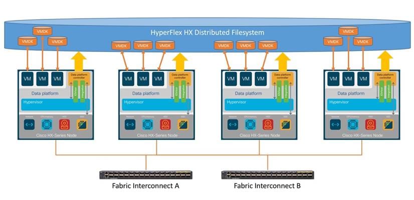
Cisco HyperFlex system overview
The following are the components of a Cisco HyperFlex system for SAP HANA in an HCI deployment:
● One pair of Cisco UCS fabric interconnects:
◦ Cisco UCS 6332 Fabric Interconnect or Cisco UCS 6454 Fabric interconnect
● Three to 32 Cisco HyperFlex HX-Series rack servers (minimum of four nodes recommended)
● Cisco HyperFlex HXAF220c M5SN All-NVMe rack servers
● Cisco HyperFlex HX Data Platform software
● VMware vSphere ESXi hypervisor
● VMware vCenter Server (end-user supplied)
● VMware vCenter plug-in
● Cisco HyperFlex Connect
● Cisco Intersight™ platform
Cisco Hyperflex Requirements for SAP HANA on HCI
The following sections detail the physical hardware, software revisions, and firmware versions used to install a four-node cluster of the Cisco HyperFlex system for SAP HANA in an HCI certification testing.
Table 1 lists the physical components for the solution used in the Certification configuration.
Table 1. Cisco HyperFlex system components
| Component |
Hardware required |
| Fabric interconnects |
2 Cisco UCS 6332-16UP Fabric Interconnects or 2 Cisco UCS 6454 Fabric Interconnects |
| Servers |
4 Cisco HyperFlex HX220c M5SN All NVMe rack-mount servers |
For complete server specifications and more information, please refer to the Cisco HyperFlex HX220c M5SN All NVMe Node specification sheet: https://www.cisco.com/c/dam/en/us/products/collateral/hyperconverged-infrastructure/hyperflex-hx-series/hxaf220c-m5-specsheet-nvme.pdf.
Table 2 lists the hardware component options for one Cisco HyperFlex HX220c M5SN All NVMe server model, as an example which was used for the SAP HANA certification.
Table 2. Cisco HyperFlex HX220c M5SN All NVMe node sample server configuration
| Cisco HyperFlex HX240c M5SX All NVMe Node options |
Hardware required |
| Processors |
2nd Generation Intel Xeon Scalable CPU (All models certified for SAP HANA TDI with 8 or more cores and listed in the Cisco HyperFlex compatibility list are supported.) |
| Memory |
12 x 64-GB (768-GB) double-data-rate 4 (DDR4) 2933-MHz 1.2V modules |
| Disk controller |
Cisco 12-Gbps modular SAS host bus adapter (HBA) |
| Hard drives |
● System log drive: 1 x 1-TB 2.5-inch NVMe drive
● Cache drive: 1 x 375-GB 2.5-inch Intel
® Optane
™ NVMe extreme-performance SSD
● Capacity and storage drive: 6 x 4-TB 2.5-inch NVMe high-performance drive
|
| Network |
Cisco UCS Virtual Interface Card (VIC) 1387 modular LAN on motherboard (mLOM) or 1457 modular LAN on motherboard (mLOM) |
| Boot device |
1 x 240-GB M.2 form-factor SATA SSD |
| Optional |
Cisco QSFP to SFP or SFP+ Adapter (QSA) module to convert 40 Gigabit Ethernet Quad Enhanced Small Form-Factor Pluggable (QSFP+) to 10 Gigabit Ethernet SFP+ |
Table 3 lists the software components and the versions used for the Cisco HyperFlex system to certify to run SAP HANA.
Table 3. Software components used for certification
| Component |
Software required |
| Hypervisor |
VMware ESXi 6.7.0 U3-13932383 (Cisco custom image for ESXi 6.7 to be downloaded from Cisco.com Downloads portal) |
| Management server |
VMware vCenter Server for Windows or vCenter Server Appliance Release 6.7 or later |
| Cisco HyperFlex HX Data Platform |
Cisco HyperFlex HX Data Platform Software Release 4.0.2a or later |
| Cisco UCS firmware |
Cisco UCS Infrastructure Software, B-Series and C-Series bundles, Release 4.0(4h) or later |
| SAP HANA |
SAP HANA 2.0 Release 37 or later |
The Cisco HyperFlex system is composed of a pair of Cisco UCS fabric interconnects along with up to 32 HX-Series rack-mount servers per cluster. You can install up to eight separate HX-Series clusters under a single pair of fabric interconnects. The fabric interconnects both connect to every HX-Series rack-mount server. Upstream network connections, also referred to as northbound network connections, are made from the fabric interconnects to the customer data center network at the time of installation (Figure 2).
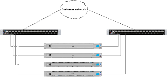
Cisco HyperFlex standard cluster topology & Cisco HyperFlex converged nodes
Cabling
The fabric interconnects and HX-Series rack-mount servers need to be cabled properly before you begin the installation activities.
Table 4 provides a sample cabling map for installation of a Cisco HyperFlex system with four Cisco HyperFlex converged servers.
Table 4. Sample fabric interconnect cabling map for 6332-UP Fabric Interconnect
| Device |
Port |
Connected to |
Port |
Type |
Length |
Note |
| UCS6332-A |
L1 |
UCS6332-B |
L1 |
CAT5 |
1 ft |
|
| UCS6332-A |
L2 |
UCS6332-B |
L2 |
CAT5 |
1 ft |
|
| UCS6332-A |
mgmt0 |
Customer LAN |
|
|
|
|
| UCS6332-A |
1/1 |
HX-Series server 1 |
mLOM port 1 |
Twinax |
3m |
Server 1 |
| UCS6332-A |
1/2 |
HX-Series server 2 |
mLOM port 1 |
Twinax |
3m |
Server 2 |
| UCS6332-A |
1/3 |
HX-Series server 3 |
mLOM port 1 |
Twinax |
3m |
Server 3 |
| UCS6332-A |
1/4 |
HX-Series server 4 |
mLOM port 1 |
Twinax |
3m |
Server 4 |
| UCS6332-A |
1/5 |
|
|
|
|
|
| UCS6332-A |
1/6 |
|
|
|
|
|
| UCS6332-A |
1/7 |
|
|
|
|
|
| UCS6332-A |
1/8 |
|
|
|
|
|
| UCS6332-A |
1/9 |
|
|
|
|
|
| UCS6332-A |
1/10 |
|
|
|
|
|
| UCS6332-A |
1/11 |
|
|
|
|
|
| UCS6332-A |
1/12 |
|
|
|
|
|
| UCS6332-A |
1/13 |
|
|
|
|
|
| UCS6332-A |
1/14 |
|
|
|
|
|
| UCS6332-A |
1/15 |
|
|
|
|
|
| UCS6332-A |
1/16 |
|
|
|
|
|
| UCS6332-A |
1/17 |
|
|
|
|
|
| UCS6332-A |
1/18 |
|
|
|
|
|
| UCS6332-A |
1/19 |
|
|
|
|
|
| UCS6332-A |
1/20 |
|
|
|
|
|
| UCS6332-A |
1/21 |
|
|
|
|
|
| UCS6332-A |
1/22 |
|
|
|
|
|
| UCS6332-A |
1/23 |
|
|
|
|
|
| UCS6332-A |
1/24 |
|
|
|
|
|
| UCS6332-A |
1/25 |
Customer LAN |
|
|
|
Uplink |
| UCS6332-A |
1/26 |
Customer LAN |
|
|
|
Uplink |
| UCS6332-A |
1/27 |
|
|
|
|
|
| UCS6332-A |
1/28 |
|
|
|
|
|
| UCS6332-A |
1/29 |
|
|
|
|
|
| UCS6332-A |
1/30 |
|
|
|
|
|
| UCS6332-A |
1/31 |
|
|
|
|
|
| UCS6332-A |
1/32 |
|
|
|
|
|
| UCS6332-B |
L1 |
UCS6332-A |
L1 |
Cat5 |
1 ft |
|
| UCS6332-B |
L2 |
UCS6332-A |
L2 |
Cat5 |
1 ft |
|
| UCS6332-B |
mgmt0 |
Customer LAN |
|
|
|
|
| UCS6332-B |
1/1 |
HX-Series server 1 |
mLOM port 2 |
Twinax |
3m |
Server 1 |
| UCS6332-B |
1/2 |
HX-Series server 2 |
mLOM port 2 |
Twinax |
3m |
Server 2 |
| UCS6332-B |
1/3 |
HX-Series server 3 |
mLOM port 2 |
Twinax |
3m |
Server 3 |
| UCS6332-B |
1/4 |
HX-Series server 4 |
mLOM port 2 |
Twinax |
3m |
Server 4 |
| UCS6332-B |
1/5 |
|
|
|
|
|
| UCS6332-B |
1/6 |
|
|
|
|
|
| UCS6332-B |
1/7 |
|
|
|
|
|
| UCS6332-B |
1/8 |
|
|
|
|
|
| UCS6332-B |
1/9 |
|
|
|
|
|
| UCS6332-B |
1/10 |
|
|
|
|
|
| UCS6332-B |
1/11 |
|
|
|
|
|
| UCS6332-B |
1/12 |
|
|
|
|
|
| UCS6332-B |
1/13 |
|
|
|
|
|
| UCS6332-B |
1/14 |
|
|
|
|
|
| UCS6332-B |
1/15 |
|
|
|
|
|
| UCS6332-B |
1/16 |
|
|
|
|
|
| UCS6332-B |
1/17 |
|
|
|
|
|
| UCS6332-B |
1/18 |
|
|
|
|
|
| UCS6332-B |
1/19 |
|
|
|
|
|
| UCS6332-B |
1/20 |
|
|
|
|
|
| UCS6332-B |
1/21 |
|
|
|
|
|
| UCS6332-B |
1/22 |
|
|
|
|
|
| UCS6332-B |
1/23 |
|
|
|
|
|
| UCS6332-B |
1/24 |
|
|
|
|
|
| UCS6332-B |
1/25 |
Customer LAN |
|
|
|
Uplink |
| UCS6332-B |
1/26 |
Customer LAN |
|
|
|
Uplink |
| UCS6332-B |
1/27 |
|
|
|
|
|
| UCS6332-B |
1/28 |
|
|
|
|
|
| UCS6332-B |
1/29 |
|
|
|
|
|
| UCS6332-B |
1/30 |
|
|
|
|
|
| UCS6332-B |
1/31 |
|
|
|
|
|
| UCS6332-B |
1/32 |
|
|
|
|
|
Cisco HyperFlex HX-Series system management components
The Cisco HyperFlex HX-Series system is managed using the following Cisco software components:
● Cisco UCS Manager
◦ Cisco UCS Manager is embedded software that resides on a pair of fabric interconnects, providing complete configuration and management capabilities for Cisco HyperFlex HX-Series servers. The most common way to access Cisco UCS Manager is to use a web browser to open the GUI. Cisco UCS Manager supports role-based access control (RBAC).
◦ The configuration information is replicated between two Cisco UCS fabric interconnects, providing a high-availability solution. If one fabric interconnect becomes unavailable, the other takes over.
◦ An important benefit of Cisco UCS Manager is the use of stateless computing. Each node in an HX-Series cluster has no set configuration. MAC addresses, universally unique IDs (UUIDs), firmware, and BIOS settings, for example, are all configured on Cisco UCS Manager in a service profile and applied uniformly to all the HX-Series servers. This approach enables consistent configuration and ease of reuse. A new service profile can be applied in minutes.
● Cisco HyperFlex HX Data Platform
◦ Cisco HyperFlex HX Data Platform is a hyperconverged software appliance that transforms Cisco servers into a single pool of computing and storage resources. It eliminates the need for network storage and tightly integrates with VMware vSphere and its existing management application to provide a seamless data management experience. In addition, native compression and deduplication reduce the amount of storage space occupied by virtual machines.
◦ HX Data Platform is installed on a virtualized platform, such as vSphere. It manages the storage for your virtual machines, applications, and data. During installation, you specify the Cisco HyperFlex cluster name, and HX Data Platform creates a hyperconverged storage cluster on each node. As your storage needs increase and you add nodes to the cluster, HX Data Platform balances the storage across the additional resources.
● VMware vCenter management
◦ Cisco HyperFlex systems use VMware vCenter–based management. The vCenter Server is a data center management server application developed to monitor virtualized environments. HX Data Platform can also be accessed from the preconfigured vCenter Server to perform all storage tasks. vCenter supports important shared storage features such as VMware vMotion, Distributed Resource Scheduler (DRS), High Availability (HA), and vSphere replication. More scalable native HX Data Platform snapshots and clones replace VMware snapshots and cloning capabilities.
You must have vCenter installed on a separate server to access HX Data Platform. vCenter is accessed through the vSphere Client, which is installed on the administrator's laptop system or PC.
Recommendations for SAP HANA on Cisco HyperFlex HCI solutions
SAP HANA on HCI with VMware, SAP limitations on ESXi
The current release for SAP HANA on HCI does not allow the physical socket to be shared between production SAP HANA virtual machines and the storage controller virtual machine. You can use only one socket of the Cisco HyperFlex HX-Series node to host up to two production SAP HANA virtual machines.
So with one dedicated full-socket for the SAP HANA virtual machines, two production SAP HANA virtual machines per HX-Series node can run on the All NVMe Cascade Lake–based HCI solution (meeting the CPU and RAM requirements defined by SAP).
To summarize (Figure 3):
● The storage controller virtual machine runs in ‘Boost Mode’ and uses upto 16 virtual CPUs (vCPUs) or eight cores, which can be shared to run only nonproduction SAP HANA virtual machines or other SAP workloads. You must consider this workload when choosing the frequency of the CPU.
● One socket must be dedicated for up to two production SAP HANA virtual machines.
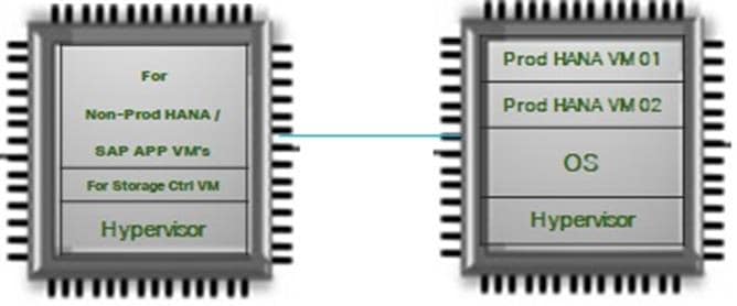
CPU placement for the virtual machines
Production SAP HANA virtual machine disk configuration
To achieve the SAP HANA performance key performance indicator (KPI) values, the virtual machines must be configured with their own Small Computer System Interface (SCSI) controllers for the data and log drives. Thus, each virtual machine will have three SCSI controllers: one controller for the OS and /hana/shared, one controller for the data drives, and one controller for the log drives.
The data and log file systems require four drives for each file system and must be configured to use their own SCSI controllers. The four drives are configured using Linux logical volume management (LVM).
Installing a Cisco HyperFlex node
Cisco HyperFlex system installation is performed primarily through a deployable Cisco HyperFlex installer virtual machine, available for download as an OVA file at Cisco.com. The installer virtual machine performs most of the Cisco UCS configuration work, and you can use it to simplify the installation of ESXi on the Cisco HyperFlex hosts. The installer virtual machine also performs significant portions of the ESXi configuration. You also can use the installer virtual machine to install the Cisco HyperFlex HX Data Platform software and create the Cisco HyperFlex cluster.
Since this is covered under the scope of this document, you can find the Cisco HyperFlex installation instructions in Cisco HyperFlex Systems Installation Guide for VMware ESXi, Release 4.0.
Note: When installing the Cisco HyperFlex system, choose replication factor 2 (RF2) to meet the KPI requirements for SAP HANA.
Cisco HyperFlex system postinstallation check
After you have installed the Cisco HyperFlex system, you can use the new HTML 5–based web user interface as the primary management tool for Cisco HyperFlex systems (Figure 4). Through this centralized point of control for the cluster, administrators can create volumes, monitor data platform health, and manage resource use. Administrators also can use this data to predict when the cluster needs to be scaled. To use the Cisco HyperFlex Connect user interface, connect using a web browser to the Cisco HyperFlex cluster IP address: http://<hx controller cluster ip>.
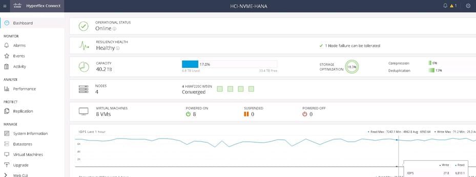
Cisco HyperFlex Connect GUI
Enable Boost mode for storage controllers
In order to achieve the SAP HANA on HCI KPI results defined by SAP, the Hyperflex Boost mode required to be enabled on the storage controller virtual machines of the cluster. HyperFlex Boost Mode increases the available storage IOPs of a Cisco HyperFlex (HX) cluster. It does this by increasing the number of vCPUs allocated to the storage controller Virtual Machine (VM) by four. HyperFlex Boost Mode is a manual process that is supported for the limited set of configurations.
So,for our example cluster configuration the vCPU resources for the storage controller Virtual machines will be increased from 12 to 16.
Please follow the whitepaper HyperFlex Boost Mode White Paper to configure the Boost mode in Cisco HyperFlex HX220c M5 All NVMe nodes.
Note: This is a mandatory requirement to achieve the performance of SAP HANA Virtual Machines.
Creating a SAP HANA virtual machine for OS installation
This section explains how to create a single virtual machine for a production SAP HANA environment that is ready for OS installation. As specified in the current supported certification scenario, you can have one production SAP HANA virtual machine per HX-Series node.
You must repeat the same steps to create additional production SAP HANA virtual machines on the other HX-Series nodes.
Remember that you can have only one SAP HANA production virtual machine per HX-Series node, so use caution when creating the virtual machines.
These steps show how to create a 512-GB virtual machine to run a production SAP HANA environment as an example. Follow the same steps to create additional virtual machines for a production SAP HANA environment, and remember to host only one production SAP HANA virtual machine per HX-Series node.
1. After the Cisco HyperFlex system is installed and accessible, log in to VMware vSphere to access the vCenter instance for the Cisco HyperFlex cluster: https://<vSphere IP address>.
2. After logging in to vSphere, from the Home menu at the top of the screen, click the Hosts & Clusters icon. Hosts & Clusters displays the connected Cisco HX-Series and ESX nodes and the storage controller virtual machines running on the nodes. These storage controller virtual machine configurations should never be modified because doing so would void support for the cluster..
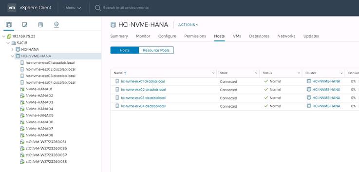
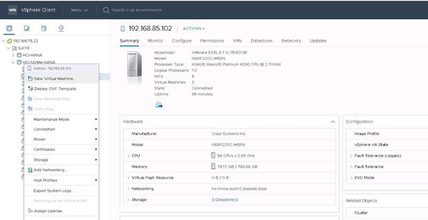
3. Right-click the cluster and choose New Virtual Machine to create the virtual machine.
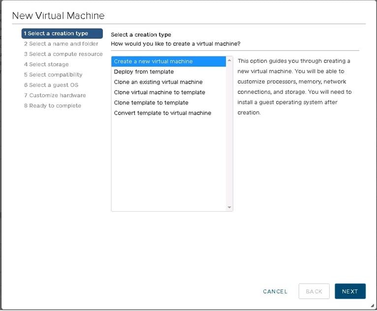
4. On the next screen that appears, select “Create a new virtual machine” and click Next at the bottom.
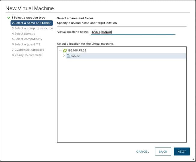
5. On the next screen, enter the name of the SAP HANA virtual machine and choose the vCenter data center that was created. Then click Next.
6. On the next screen, choose the computing resource or HX-Series node on which the SAP HANA virtual machine is to be placed and click Next.
Note: As specified for the current certified solution for Cisco HyperFlex for SAP HANA on HCI, two production SAP HANA virtual machines can be configured per HX-Series node.
7. After you have selected the HX-Series node for SAP HANA virtual machine placement, select the datastore for the virtual machine that was created during the Cisco HyperFlex installation. Click Next.
8. Choose the compatibility option as desired and click Next.
9. For the OS family, choose Linux and then choose the desired OS version. Then click Next.
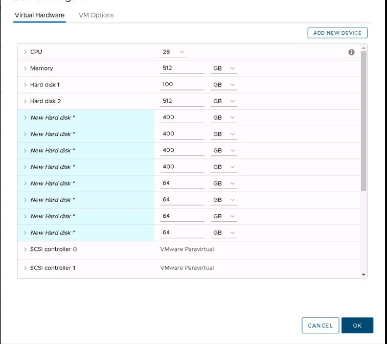
On the next screen, you customize the resources needed to run the production SAP HANA virtual machine. As stated in the previous section, using the Cascade Lake HCI solution you can have two production SAP HANA virtual machines per HX-Series node. You choose the number of vCPUs according to the CPU model used. You also need to set the NUMA node affinity of these SAP HANA virtual machines to use only the second non-uniform memory access (NUMA) node of the HX-Series node.
This guide uses the Intel Xeon Platinum processor 8280 as an example. This CPU model has 28 physical cores and 56 logical threads. The below example shows how to assign a Half socket for the SAP HANA virtual machine. Depending on the installation requirement this setting needs to be adjusted if the HANA virtual machine configured for a full socket.
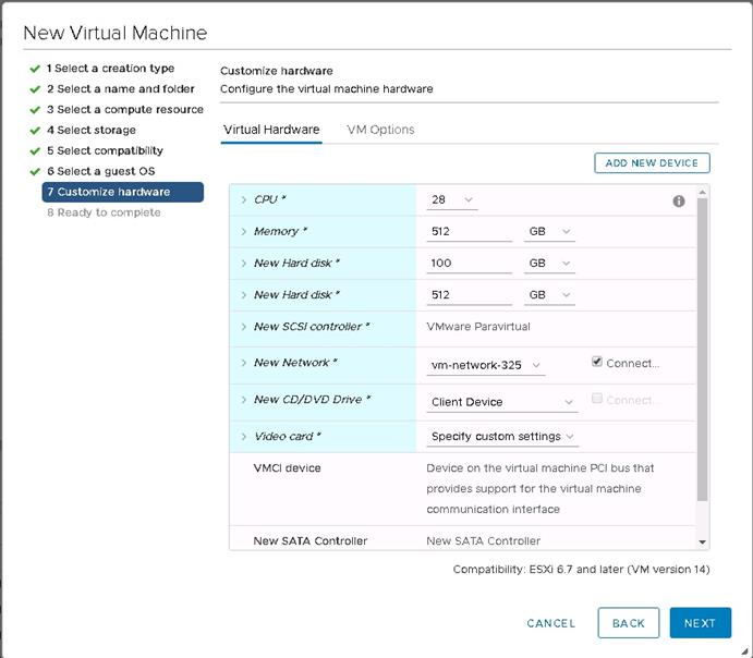
10. In this example, for the first virtual machine set the CPU resource to 28 and the number of cores per socket to 28. Then click Next.
![]()
11. In this example, 512 GB is RAM is used. Add two hard disks: one with 100 GB for the operating system and one with 512 GB for the HANA shared file system.
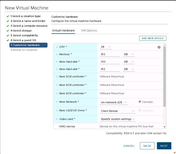
You will be adding storage controllers for the data and log drives, so continue by adding two SCSI controllers in the next steps and finish by creating the virtual machine. Then you can create the drives used.
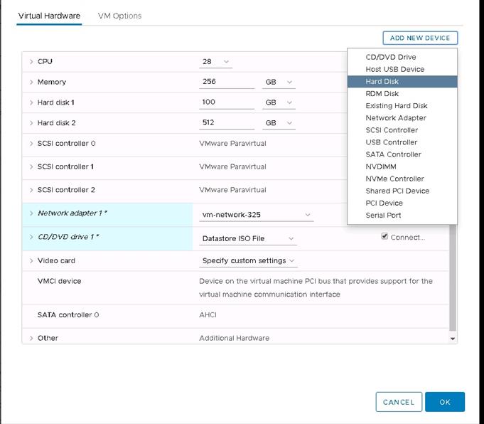
12. On the next screen, click Add New Device and choose SCSI Controller to add the second SCSI controller for the HANA data drives. One SCSI controller is available by default, so you need to add two more SCSI controllers.
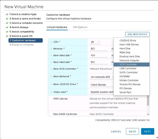
13. Repeat step 12 to add the third SCSI controller for the HANA log drives.
14. Select the network vm-network-xx to allow access to the virtual machine in the network.
15. Select Datastore ISO File and choose the appropriate ISO file from the drop-down menu. The SLES server ISO file is used in this example. This ISO file must be uploaded to the datastore prior to this selection.
16. Select the Connect checkbox.
17. Click Next to review the configuration and finish creating the virtual machine.
Note: You have not yet added the hard disks for the HANA data and HANA log file systems. This process is covered in the following steps.
Pinning the Production SAP HANA Virtual Machine with NUMA node
SAP states that in a HCI environment, the production SAP HANA virtual machine cannot share the socket with storage controller of the HCI or non-production HANA virtual machines. In order to adhere this rule, the SAP HANA virtual machine should be pinned to the NUMA node which does not have the storage controller virtual machine assigned.
Note: This is a critical step to have the support from SAP for the production HANA virtual machines on HCI.
In Cisco Hyperflex HCI, since HXAF220c M5SN is a 2 socket server, the storage controller uses the NUMA node 0 and hence production the SAP HANA virtual machine needs to be assigned with NUMA node 1.
Please follow the steps below to assign the production SAP HANA virtual machine to NUMA node 1.
1. From the vsphere Datacenter, right click the SAP HANA virtual Machine and click settings.
2. Select VM options from the Edit window.
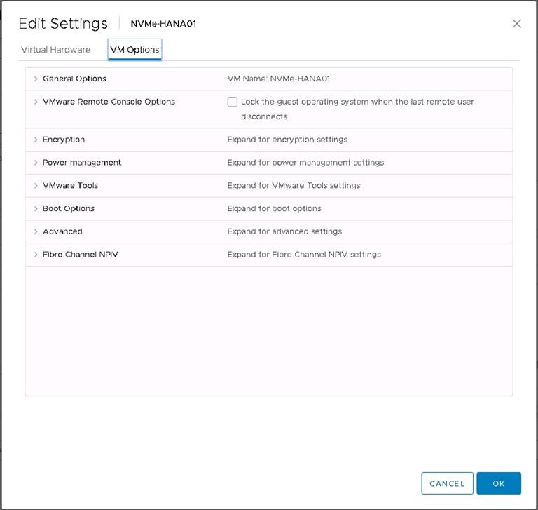
3. Expand the ‘Advanced’ menu and click ‘Edit Configuration’
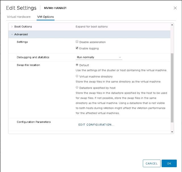
4. In the Configuration parameters window, Click ‘Add Configuration Params’
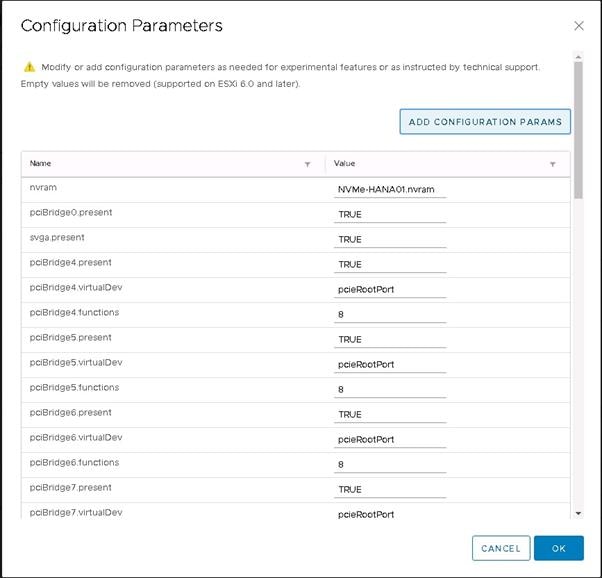
5. Enter the param name ‘numa.nodeAffinity’ and the value ‘1’
![]()
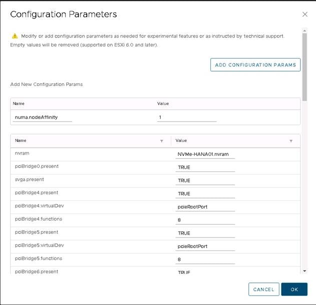
6. Click Ok to save the settings and proceed further to add disks for Data and Log filesystems.
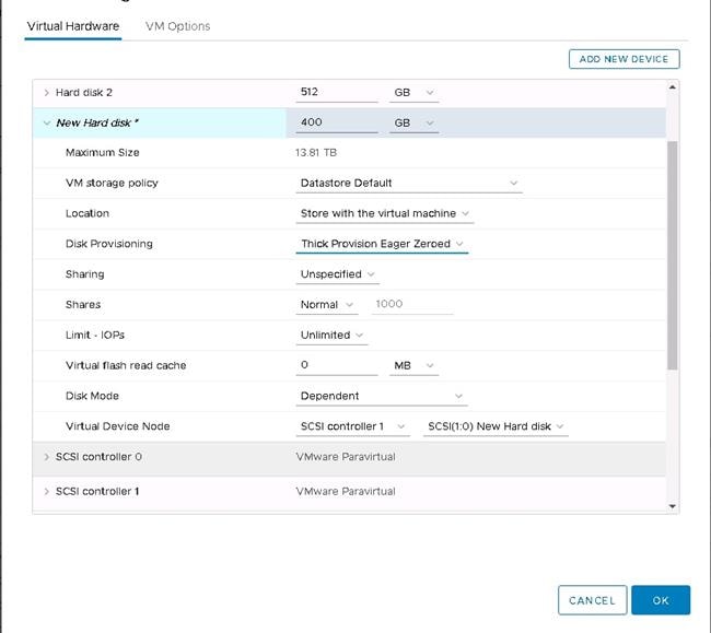
The next step is to add disks for the HANA data and log file systems.
In this example, for the SAP HANA virtual machine with 512 GB of RAM, you need 1.5 TB of disk space for the data file system and 256 GB of disk space for log file system. To meet the SAP HANA KPI values, you need four drives for the data file system and four drives for the log file system configured with individual SCSI controllers. This requirement is very important for performance.
So for the data file system of 1.5 TB, you need four drives, each with 400 GB. For the log file system of 256 GB, you need four drives, each with 64 GB.
Remember to calculate the size of the disks based on the memory requirements of the SAP HANA virtual machine that is being installed.
7. From the Add New Device drop-down menu, choose Hard Disk.
8. For the size of the hard disk, enter 400 GB. Expand the settings for this drive and for Disk Provisioning, choose Thick Provision Eager Zeroed. For Virtual Device Node, choose “SCSI controller 1.”
![]()
![]()
9. Repeat step 19 to add three more 400-GB disks for the data file systems. Verify that all four drives are in the same SCSI controller, which is independent for these disks.
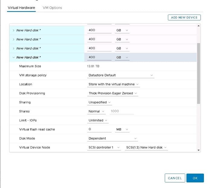
Now add the drives for the log file system. In this example, you need four drives, each 64 GB in size.
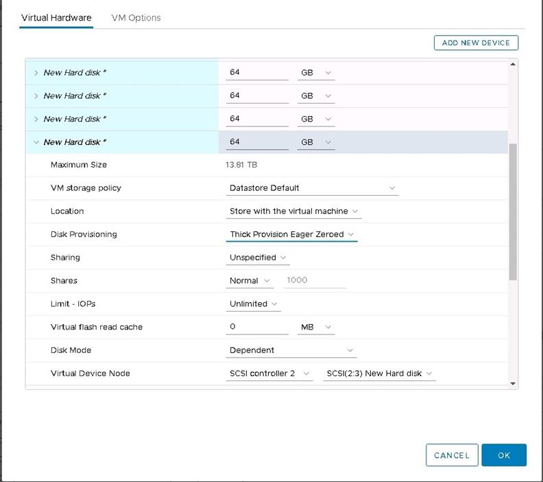
10. Click Add New Device and choose Hard Disk.
For the size, enter 64 GB. Expand the settings for this drive and for Disk Provisioning, choose Thick Provision Eager Zeroed. For Virtual Device Node, choose “SCSI controller 2.”
![]()
![]()
![]()
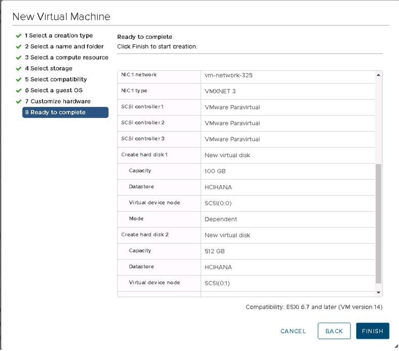
11. After you have added all the drives, review the settings before submitting them.
12. Click OK to create the virtual machine.
Now the virtual machine is ready for the OS installation.
Installing the operating system on the SAP HANA virtual machine
To install the SLES 12 for SAP SP4 OS, perform the following steps:
1. Mount the SLES for SAP 12 SP3 ISO file from the datastore.
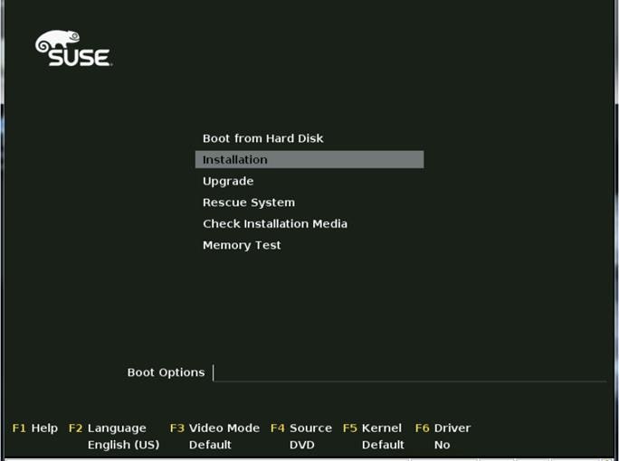
2. Power on the virtual machine created in the preceding steps.
3. From the boot menu, select Installation.
4. On the Language, Keyboard and License Agreement page, select your preferred language and keyboard layout, agree to the license terms, and select Next.
5. On the Network Settings page, select Next. You will return to the network configuration as part of the postinstallation tasks.
6. On the Registration page, select Skip Registration. You will register later as part of the postinstallation tasks.
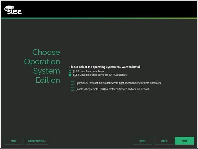
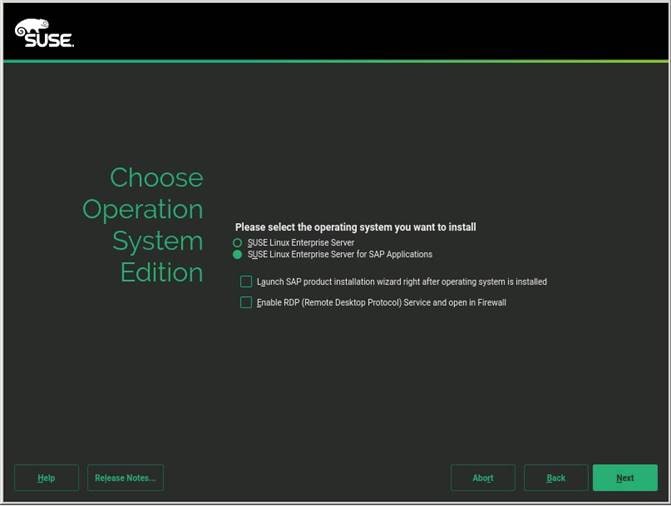
7. On the Product Installation Mode page, select the “Proceed with standard SLES for SAP Applications” installation option.
8. On the Add On Product page, select Next. In this configuration example, there are no additional products to install.
9. On the Suggested Partitioning page, select Expert Partitioner.
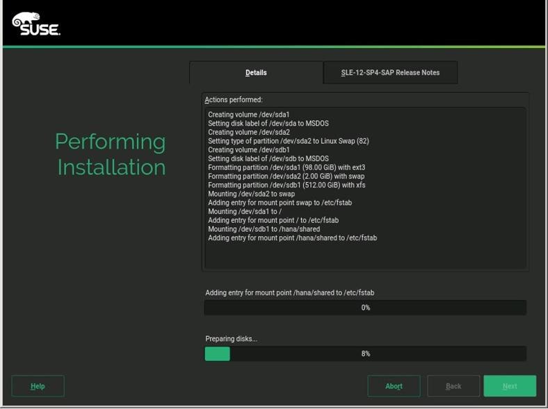
10. At the left, choose System View > Linux > Hard Disks > sda.
11. Create partitions with sizes based on the memory size of the SAP HANA virtual machine.
You will create only the OS partition and the partition for the HANA shared file system.
The sizes in Table 5 are examples calculated based on the sample installation of an SAP HANA virtual machine with 512 GB of memory.
Table 5. Partition sizes for OS and HANA shared file system
| Disk |
Partition |
Type |
Mount |
Size |
| sda |
sda1 |
ext3 |
/ |
98 GB |
|
|
sda2 |
Swap |
Swap |
2 GB |
| sdb |
sdb1 |
XFS |
Shared |
512 GB |
You will create the data and log file systems using striped LVM after the installation of the operating system. This process is covered in the “Postinstallation VMware and OS configuration tasks” section. Use Table 6 for reference.
Table 6. Example Partition sizes for HANA data and log file systems
| Disk |
LVM type |
Volume group |
Logical volume |
Type |
Mount |
Size |
| sd(c,d,e,f) |
Striped |
datavg |
datavol |
XFS |
Data |
1.5 TB |
| sd(g,h,I,j) |
Striped |
logvg |
logvol |
XFS |
Log |
256 GB |
After you have created the OS and HANA shared partitions, the partition information should look like the following screenshot.
12. Review the updated partition information and then click Next.
13. For Clock and Time Zone, choose the appropriate time zone and set the hardware clock to UTC.
14. For the password for the system administrator root, enter an appropriate password.
15. On the Installation Settings screen, review the default information.
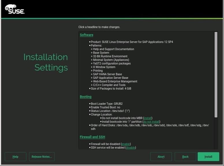
16. Now customize the software selection. Click the Software headline to make changes as follows:
a. Deselect Gnome Desktop Environment.
b. Select C/C++ Compiler and Tools.
c. Select SAP HANA Server Base.
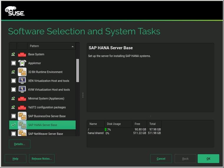
17. Click OK.
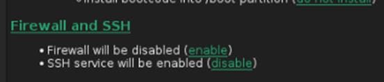
18. Under the Firewall and SSH headline, disable the firewall. This selection automatically enables Secure Shell (SSH) Protocol service.
19. Click the Set Default Systemd Target headline and select “Text mode.”
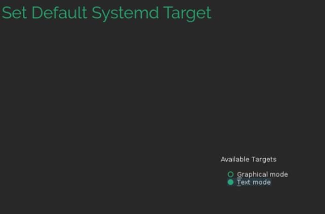
20. Click OK.
21. Leave the Booting and System default selections unchanged.
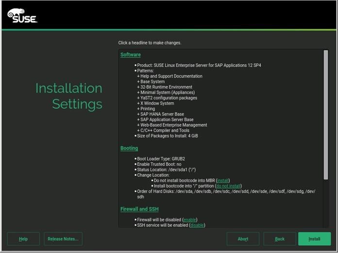
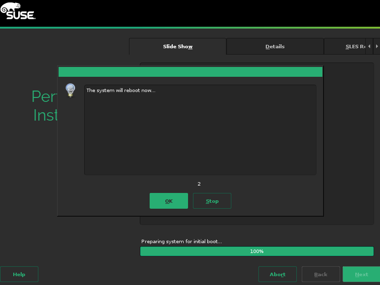
22. Click Install. Also click Install at subsequent Confirm Installation prompts. The installation starts, and you can monitor the status.
23. You will see a reboot alert when the installation is complete. Click OK and then Next.
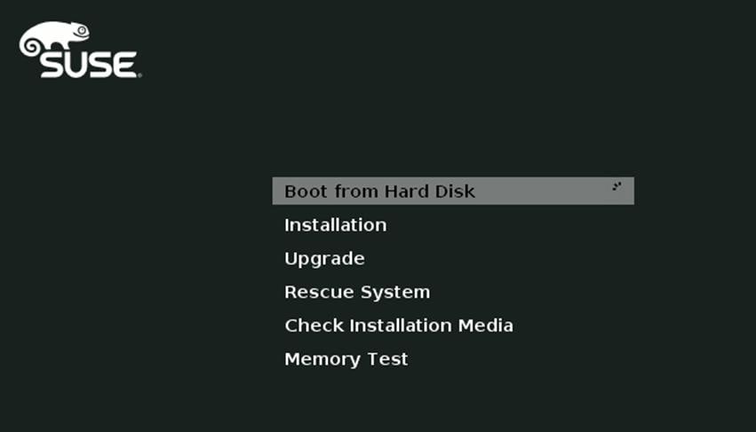
24. The system will reboot and boot from the disk on startup. Select Boot from Hard Disk.
The system then displays the login prompt:
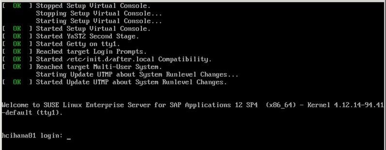
25. Use the VMware console to log in to the installed system as the user root with the password <root password>.
26. Configure the host name and disable IPv6. Open YaST Control Center:
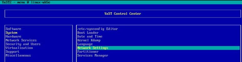
27. Choose System > Network Settings and press Alt+S to select the Hostname/DNS tab.
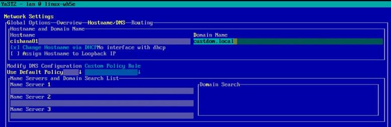
28. Enter the host name and enter the Domain Name System (DNS) server address of your network for resolution, if necessary. Then press Alt+O.
29. On the Global Options tab, using Alt+G disable IPv6 by deselecting the Enable IPv6 option.
Note that changing the IPv6 setting requires a reboot to make the change take effect.
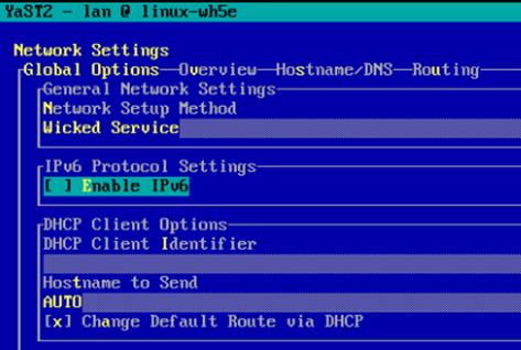
30. Press Alt+O to save the network configuration. Press Alt+Q to quit the YaST Control Center.
31. Reboot the server to make the IPv6 selection and the host-name settings take effect:
32. Use the ifconfig command to see a list of the available virtual machine interface names, and go to the network configuration directory and create a configuration. In this example, the device name is eth1.
33. Add the default gateway.
Note: Be sure that the system has access to the Internet or a SUSE update server to install the patches.
34. Verify /etc/hosts.
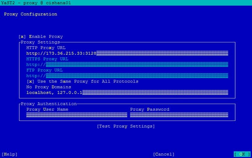
35. If required, set up a proxy service so that the appliance can reach the Internet.
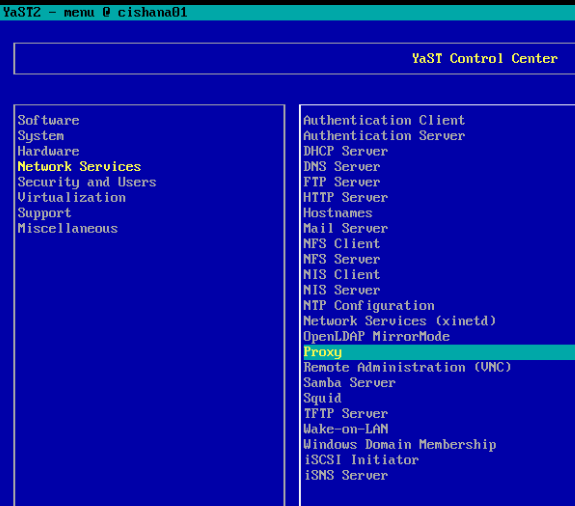
36. Enter the proxy server and port as shown in the following sample configuration. Select OK and then quit YaST to save the configuration.
37. Register the system with SUSE to receive the latest patches. For more information, refer to the SUSE knowledgebase article at https://www.suse.com/de-de/support/kb/doc?id=7016626. The system must have access to the Internet to proceed with this step.
38. Update the system with the following command. Again, the system must have access to the Internet to proceed with this step.
39. Follow the on-screen instructions to complete the update process. Reboot the server and log in to the system again.
Postinstallation VMware and OS configuration tasks
To optimize the use of the SAP HANA database with SLES 12 or SLES for SAP 12 SP3, apply the settings by referring to this SAP Note: 2205917: SAP HANA DB: Recommended OS settings for SLES 12 / SLES for SAP Applications 12.
Refer the SAP Note 2161991: VMware vSphere configuration guidelines for recommended configuration guidelines for VMware vSphere.
Preparing the HANA data file system
The next task is to prepare the four drives for the HANA data file system.
1. Create physical volumes on the four drives for HANA data.
2. Create volume group datavg using the four drives for HANA data.
3. Create the striped logical volume datavol in the volume group datavg.
4. Format the logical volume to use the XFS file system.
Preparing the HANA log file system
The next task is to prepare the four drives for the HANA log file system.
1. Create physical volumes on the four drives for the HANA log.
2. Create volume group datavg using the four drives for the HANA log.
3. Create the striped logical volume logvol in the volume group logvg.
4. Format the logical volume to use the XFS file system.
Mounting and checking the file systems
Now mount and validate the file systems.
1. Create the mount points to create the HANA data and log file systems.
2. Mount the file systems.
3. Check the mounted file system.
4. A sample /etc/fstab entry is shown here. Verify that your entries for the data and log file systems are added as shown in the example.
5. Change the directory permissions before you install SAP HANA. Use the chown command on each SAP HANA node after the file systems are mounted.
Use the official SAP documentation, which describes the installation process with and without the SAP unified installer.
For the SAP HANA installation documentation, refer to the SAP HANA Server Installation Guide.
All other SAP installation and administration documentation is available at http://service.sap.com/instguides.
Read the following SAP Notes before you start the installation. These SAP Notes contain the latest information about the installation, as well as corrections to the installation documentation.
The latest SAP Notes are available at https://service.sap.com/notes.
SAP HANA in-memory database (IMDB) notes
● SAP note 1514967: SAP HANA: Central note
● SAP note 2298750: SAP HANA Platform SPS 12 Release Note
● SAP note 1523337: SAP HANA database: Central note
● SAP note 2000003: FAQ: SAP HANA
● SAP note 2380257: SAP HANA 2.0 Release Notes
● SAP note 1681092: Support for multiple SAP HANA databases on a single SAP HANA appliance
● SAP note 1514966: SAP HANA: Sizing the SAP HANA database
● SAP note 1637145: SAP BW on HANA: Sizing the SAP HANA database
● SAP note 1793345: Sizing for Suite on HANA
● SAP note 2205917: SAP HANA DB: Recommended OS settings for SLES 12 and SLES for SAP Applications 12
● SAP note 2235581: SAP HANA: Supported operating systems
● SAP note 1944799: SAP HANA guidelines for the SLES operating system
● SAP note 1557506: Linux paging improvements
● SAP note 1740136: SAP HANA: Wrong mount option may lead to corrupt persistency
● SAP note 1730928: Using external software in a SAP HANA appliance
● SAP note 1730929: Using external tools in a SAP HANA appliance
● SAP note 1730930: Using antivirus software in a SAP HANA appliance
● SAP note 1730932: Using backup tools with Backint for SAP HANA
SAP HANA virtualization notes
● SAP note 2652670: SAP HANA VM on VMware vSphere
● SAP note 2161991: VMware vSphere configuration guidelines
● SAP note 2393917: SAP HANA on VMware vSphere 6.5 and 6.7 in production
● SAP note 2015392: VMware recommendations for latency-sensitive SAP applications
SAP HANA postinstallation checkup
For an SAP HANA system installed with the system ID <SID> set to CLX and the system number <nr> set to 00, log in as <sid>adm ir CLXadm and run the commands presented here. Commands for checking SAP HANA services follow.
Tuning the SAP HANA performance parameters
After SAP HANA is installed, tune the parameters as shown in Table 7 and explained in the following SAP Notes.
Table 7. Tuning parameters
| Parameters |
Data file system |
Log file system |
| max_parallel_io_requests |
256 |
Default |
| async_read_submit |
On |
On |
| async_write_submit_blocks |
All |
All |
| async_write_submit_active |
On |
On |
For SAP HANA 2.0 installations, use either SAP HANA HDBSQL or the Structured Query Language (SQL) function in SAP HANA Studio or the cockpit and the following SQL commands:
For more information, refer to SAP Note 2399079: Elimination of hdbparam in HANA 2.
To download revisions, you need to connect to the service marketplace and select the software Download area to search for available patches.
Refer to http://help.sap.com/hana/SAP_HANA_Master_Update_Guide_en.pdf for update procedures for SAP HANA.
● For information about SAP HANA, refer to https://hana.sap.com/abouthana.html.
● For information about certified and supported SAP HANA hardware, refer to https://global.sap.com/community/ebook/2014-09-02-hana-hardware/enEN/index.html.