Hardware and VMware Hosting Requirements (top)
The Packaged CCE deployment at the customer site must run in a duplexed environment with a pair of Unified Computing System (UCS) servers. These servers are referred to as Side A Host and Side B Host.
The two Packaged CCE servers must use the same server model.
- Co-residency support = None
- Supported Versions of VMWare vSphere ESXi
- 5.5 update 2 or later, 6.0 update 2 or later on VM Version 9
- Supported Hardware
- UCS Tested Reference Configurations for fresh installs or technology refreshes
- UCS Tested Reference Configurations for common ground upgrades
- UCS or 3rd-party Specs-based on Intel Xeon = Not supported
- Supported Versions of Cisco Nexus 1000V: Refer to the Host Software Version Compatibility matrix for Cisco Nexus 1000V to determine the version that is compatible with the ESXi version that you are running.
When ordering Packaged CCE with the UCS B200 M4, customers must either
already have a supported UCS B-Series platform infrastructure and SAN in
their data center or must purchase these separately. UCS B-Series blades are
not standalone servers and have no internal storage.
The Packaged CCE UCS B-Series Fabric Interconnects Validation Tool performs checks on currently deployed UCS B-Series Fabric Interconnect clusters to determine compliance with Packaged CCE requirements. This tool does not test all UCS B-Series requirements, only those related to Packaged CCE compliance. For more information, refer to Packaged CCE UCS B-Series Fabric Interconnects Validation Tool.
UCS-B Series Platform and Hardware Requirements (top)
| UCS-B Platform Series Component | Models Supported | Notes and Additional Requirements |
|---|---|---|
| UCS Blade Server | Cisco UCS B200 M3 Cisco UCS B200 M4 |
If using existing blades, the specification must match either: |
| UCS Blade Server Chassis | Cisco UCS 5108 | |
| UCS Fabric Interconnects |
|
Minimum two matching UCS fabric interconnects per Data Center site. UCS Manager version 2.2(1) minimum. Ethernet End Host mode is required. |
| UCS Fabric Extenders |
|
Two matching UCS fabric extenders per Cisco UCS 5108 Blade Server Chassis. Minimum two 10G connections per Fabric Extender to Fabric Interconnect. |
UCS B-Series Platform Storage Area Network Hardware and Transport Requirements(top)
Packaged CCE deployments on a UCS B-Series platform require a supported Storage Area Network (SAN). Packaged CCE blade servers do not come with internal storage and must use Boot from SAN.
Packaged CCE supports the following SAN transports in Fibre Channel (FC) End Host or Switch Mode:
- Fibre Channel (FC): FC 2/4/8G
- Fibre Channel over Ethernet (FCoE): 10G Ethernet
Packaged CCE requirements for SAN:
- Compatibility with the VMware HCL and UCSM Manager Server
Interoperability list for the UCSM version deployed
- Low latency, where VMware realtime performance statistic disk.totalLatency.average does not exceed 60 (milliseconds) for any Packaged CCE datastore (SAN LUN).
- Conforms with Application IOPS and bandwidth requirements met by provisioned LUNs and SAN transport. Refer to the Bandwidth Provisioning and Network QoS Considerations section in this wiki for details on application IOPS and bandwidth requirements.
The following SAN/NAS storage technologies are not supported:
- NFS
- iSCSI
- Infiniband SAN
- Deduplication
SAN LUNs with SATA/SAS 7200 RPM and slower disk drives are only supported where used in Tiered Storage Pools containing SSD (Solid State) and 10000 and/or 15000 RPM SAS/FC HDDs.
While customers may use thin provisioned LUNs, Packaged CCE VMs must be deployed Thick-provisioned, thus SAN LUNs must have sufficient storage space to accommodate all applications VMs on deployment.
UCS B-Series LAN Requirements(top)
| Topology | Requirements | Notes |
|---|---|---|
| Common-L2 |
10G Ethernet Uplinks required Each Fabric Interconnect must connect to both of two common-L2 10GE switches (cross-connect) |
Single-link, PortChannel, vPC and VSS uplinks are supported. Visible and Private networks are allowed to be converged northbound of Fabric Interconnects (pinning is not required). |
Side A Server Component Configurations for C240 M3 and M4 Servers
(top)
| Components | vCPU* | RAM (in GB) | HDD (in GB) | CPU Reservation (in MHz) | Virtual Network Adapter Type | RAM Reservation (in MB) |
|---|---|---|---|---|---|---|
| Unified CCE Rogger | 4 | 6 |
230 |
5000 | VMXNet3 | 6144 |
| Unified CCE AW/HDS/DDS | 4 | 16 |
830 | 5000 | VMXNet3 | 16384 |
| Unified CCE PG | 2 |
6 | 80 |
4000 | VMXNet3 | 6144 |
| Unified CVP Server A | 4 | 10 |
250 |
3000 | VMXNet3 | 10240 |
| Finesse | 4 | 10 | 146 | 5000 | VMXNet3 | 10240 |
| Unified CVP OAMP Server | 2 | 4 |
80 | 400 | VMXNet3 | 4096 |
| Unified Intelligence Center Publisher | 4 | 16 | 200 |
5500 | VMXNet3 | 16384 |
| Unified Communications Manager Publisher | 2 | 8 | 110 | 3600 | VMXNet3 | 8192 |
| Unified Communications Manager Subscriber 1 | 2 | 8 | 110 | 3600 | VMXNet3 | 8192 |
- vCPUs are oversubscribed by design.
Side B Server Component Configurations for C240 M3 and M4 Servers
(top)
| Components | vCPU* | RAM (in GB) | HDD (in GB) | CPU Reservation (in MHz) | Virtual Network Adapter Type | RAM Reservation (in MB) |
|---|---|---|---|---|---|---|
| Unified CCE Rogger | 4 | 6 |
230 |
5000 | VMXNet3 | 6144 |
| Unified CCE AW/HDS/DDS | 4 | 16 |
830 |
5000 | VMXNet3 | 16384 |
| Unified CCE PG | 2 |
6 | 80 |
4000 |
VMXNet3 | 6144 |
| Unified CVP Server B | 4 | 10 |
250 | 3000 |
VMXNet3 | 10240 |
| Finesse | 4 | 10 | 146 | 5000 |
VMXNet3 | 10240 |
| Unified CVP Reporting Server (optional) |
4 |
6 |
518 |
1800 |
VMXNet3 |
6144 |
| Unified Intelligence Center Subscriber | 4 | 16 | 200 |
5500 |
VMXNet3 | 16384 |
| Unified Communications Manager Subscriber 2 | 2 | 8 | 110 | 3600 | VMXNet3 | 8192 |
| Enterprise Chat and Email (C240 M4 servers only) |
4 | 20 | 430 | 4000 | VMXNet3 | 20480 |
- vCPUs are oversubscribed by design.
Network Requirements for Cisco UCS C-Series Servers (top)
The illustration below shows the reference design for all Packaged CCE deployments on UCS C-Series servers and the network implementation of the vSphere vSwitch design.
This design calls for using the VMware NIC Teaming (without load balancing) of virtual machine network interface controller (vmnic) interfaces in an Active/Standby configuration through alternate and redundant hardware paths to the network.
The network side implementation does not have to exactly match this illustration, but it must allow for redundancy and must not allow for single points of failure affecting both Visible and Private network communications.
Note: The customer also has the option, at their discretion, to configure VMware NIC Teaming on the Management vSwitch on the same or separate switch infrastructure in the data center.
Requirements:
- Ethernet interfaces must be Gigabit speed and connected to Gigabit Ethernet switches. 10/100 Ethernet is not supported.
- No single point of failure is allowed to affect both the Active and
Standby Visible network links or both the Visible and Private network
communications between Packaged CCE Side A and Side B servers at the
same time.
- Cisco Stacking technology does not meet the high availability
requirements of Packaged CCE network communications.
- A switch stack may not be used for both the Active and Standby Visible network uplinks from a single Packaged CCE server, even if those uplinks connect to separate physical switches within a stack.
- A switch stack may not be used for both the Active Visible and
Active Private network uplinks from a single Packaged CCE server,
even if those uplinks connect to separate physical switches within a
stack.
- Network switches must be configured properly for connection to VMware. Refer to the VMware Knowledge Base for details on ensuring proper switch configuration to prevent Spanning Tree Protocol (STP) delay in failover/fallback scenarios.
VMware vSwitch Design for Cisco UCS C-Series Servers (top)
This figure illustrates a configuration for the vSwitches and vmnic adapters on a UCS C-Series server using the redundant Active/Standby vSwitch NIC Teaming design. The configuration is the same for the Side A server and the Side B server.
VMware vNetwork Distributed Switch for UCS-C Series Servers (top)
The illustration below shows the reference design for Packaged CCE deployments on UCS C-Series servers with the VMware vNetwork Distributed Switch.
You must use Port Group override, similar to the configuration for the
UCS-B series servers. See the
VMware vSwitch Design for Cisco UCS B-Series Servers section below.
Data Center Switch Configuration for UCS C-Series Server Ethernet Uplinks (top)
Reference and required design for UCS C-Series server Packaged CCE Visible and Private networks Ethernet uplinks uses the VMware default of IEEE 802.1Q (dot1q) trunking, which is referred to as the Virtual Switch VLAN Tagging (VST) mode. This design requires that specific settings be used on the uplink data center switch, as described in the example below.
Improper configuration of up-link ports can directly and negatively impact system performance, operation, and fault handling.
Note: All VLAN settings are given for example purposes. Customer VLANs may vary according to their specific network requirements.
Example: Virtual Switch VLAN Tagging (top)
C3750-A1

interface GigabitEthernet1/0/1
  description PCCE_Visible_A_Active
  switchport trunk encapsulation dot1q
  switchport trunk allowed vlan 10
  switchport mode trunk
  switchport nonegotiate
  spanning-tree portfast trunk

interface GigabitEthernet1/0/2
  description PCCE_Private_A_Standby
  switchport trunk encapsulation dot1q
  switchport trunk allowed vlan 100
  switchport mode trunk
  switchport nonegotiate
  spanning-tree portfast trunk

C3750-A2

interface GigabitEthernet1/0/1
  description PCCE_Visible_A_Standby
  switchport trunk encapsulation dot1q
  switchport trunk allowed vlan 10
  switchport mode trunk
  switchport nonegotiate
  spanning-tree portfast trunk

interface GigabitEthernet1/0/2
  description PCCE_Private_A_Active
  switchport trunk encapsulation dot1q
  switchport trunk allowed vlan 100
  switchport mode trunk
  switchport nonegotiate
  spanning-tree portfast trunk

C3750-B1

interface GigabitEthernet1/0/1
  description PCCE_Visible_B_Active
  switchport trunk encapsulation dot1q
  switchport trunk allowed vlan 20
  switchport mode trunk
  switchport nonegotiate
  spanning-tree portfast trunk

interface GigabitEthernet1/0/2
  description PCCE_Private_A_Standby
  switchport trunk encapsulation dot1q
  switchport trunk allowed vlan 200
  switchport mode trunk
  switchport nonegotiate
  spanning-tree portfast trunk

C3750-B2

interface GigabitEthernet1/0/1
  description PCCE_Visible_B_Standby
  switchport trunk encapsulation dot1q
  switchport trunk allowed vlan 20
  switchport mode trunk
  switchport nonegotiate
  spanning-tree portfast trunk

interface GigabitEthernet1/0/2
  description PCCE_Private_B_Active
  switchport trunk encapsulation dot1q
  switchport trunk allowed vlan 200
  switchport mode trunk
  switchport nonegotiate
  spanning-tree portfast trunk
Note:
- ESXi supports dotlq only.
- DTP is not supported.
Network Requirements for Cisco UCS B-Series Servers (top)
The figure below shows the virtual to physical Packaged CCE
communications path from application local OS NICs to the data center
network switching infrastructure.
The reference design depicted uses a single virtual switch with two vmnics
in Active/Active mode, with Visible and Private network path diversity
aligned through the Fabric Interconnects using the Port Group vmnic override
mechanism of the VMware vSwitch.
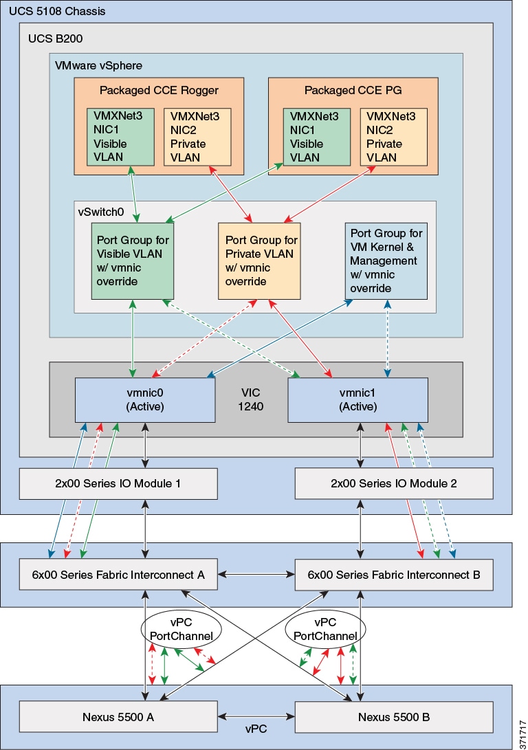
Alternate designs are allowed, such as those resembling that of UCS C-Series servers where each Port Group (VLAN) has its own vSwitch with two vmnics in Active/Standby configuration. In all designs, path diversity of the Visible and Private networks must be maintained so that both networks do not fail in the event of a single path loss through the Fabric Interconnects.
VMware vSwitch Design for Cisco UCS B-Series Servers (top)
The figures in this topic illustrate the two vmnic interfaces with Port
Group override for the VMware vSwitch on a UCS B-Series server using an
Active/Active vmnic teaming design. The configuration is the same for the
Side A and Side B servers.
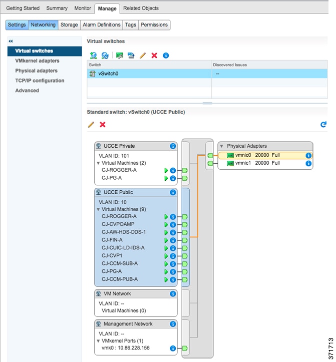
The following figure shows the Public network alignment (preferred path via
override) to the vmnic0 interface.
The following figure shows the Private networks alignment to the vmnic1 interface.
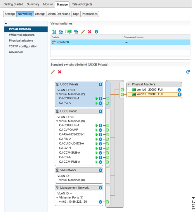
When using Active/Active vmnic interfaces, Active/Standby can be set per Port Group (VLAN) in the vSwitch dialog in the vSphere Web Client, as shown:
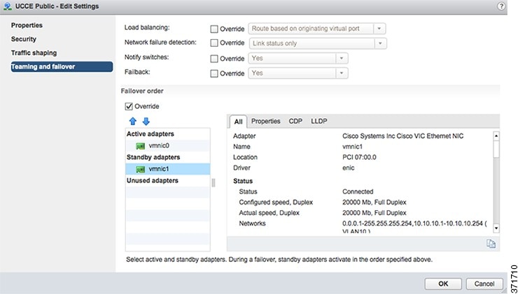
Ensure that the Packaged CCE Visible and Private networks Active and Standby vmnics are alternated through Fabric Interconnects so that no single path failure will result in a failover of both network communication paths at one time. In order to check this, you may need to compare the MAC addresses of the vmnics in vSphere to the MAC addresses assigned to the blade in UCS Manager to determine the Fabric Interconnect to which each vmnic is aligned.
UCS B-Series servers may also be designed to have 6 or more vmnic interfaces with separate vSwitch Active/Standby pairs similar to the design used for UCS C-Series servers. This design still requires that active path for Visible and Private networks be alternated between the two Fabric Interconnects.
VMware vNetwork Distributed Switch Design for Cisco UCS B-Series Servers (top)
Use the UCS B-series example configuration as a guideline for configuring the UCS B-series with a VMware vNetwork Distributed Switch.
Cisco Nexus 1000V Design for Cisco UCS B-Series Servers (top)
The figure below shows the Packaged CCE reference design for Nexus 1000V with UCS B-Series servers.
Except for the reference diagram, the requirements and configuration for the
Nexus 1000V are the same for Packaged CCE and Unified CCE. For details on
using the Nexus 1000V, see
Nexus 1000v Support in Unified CCE.
Data Center Switch Configurations for Cisco UCS B-Series Fabric Interconnect Ethernet Uplink (top)
This topic provides examples of data center switch uplink port configurations for connecting to UCS B-series Fabric Interconnects.
There are several supported designs for configuring Ethernet uplinks from
UCS B-Series Fabric Interconnects to the data center switches for Packaged
CCE. Virtual Switch VLAN Tagging is required, with EtherChannel / Link
Aggregation Control Protocol (LACP) and Virtual PortChannel (vPC) being
options depending on data center switch capabilities.
The required and reference design for Packaged CCE Visible and Private
network uplinks from UCS Fabric Interconnects uses a Common-L2 design, where
both Packaged CCE VLANs are trunked to a pair of data center switches.
Customer also may choose to trunk other management (including VMware) and
enterprise networks on these same links, or use a Disjoint-L2 model to
separate these networks from Packaged CCE.Both designs are supported, though
only the Common-L2 model is used here.
Note: All VLAN, vPC and PortChannel IDs and configuration settings are given for example purposes. Customer VLANs, IDs and any vPC timing and priority settings may vary according to their specific network requirements.
Improper configuration of up-link ports can directly and negatively impact system performance, operation, and fault handling.
Example 1: vPC Uplinks (top)
In this example, UCS Fabric Interconnect Ethernet uplinks to a pair of Cisco Nexus 5500 series switches using LACP and vPC. UCS Fabric Interconnects require LACP where PortChannel uplinks are used, regardless of whether they are vPC.
Note: Cisco Catalyst 10G switches with VSS also may be used in a similar uplink topology with VSS (MEC) uplinks to the Fabric Interconnects. That IOS configuration is not described here, and differs from the configuration of NX-OS.
N5KA

cfs ipv4 distribute
cfs eth distribute
feature lacp
feature vpc
feature lldp

vlan 1-10,100

vpc domain 1
  role priority 1000
  system-priority 4000
  peer-keepalive destination 10.0.0.2
  delay restore 180
  peer-gateway
  auto-recovery

interface port-channel1
  description vPC_to_FabricA
  switchport mode trunk
  switchport trunk allowed vlan 1-10,100
  spanning-tree port type edge trunk
  vpc 1

interface port-channel2
  description vPC_to_FabricB
  switchport mode trunk
  switchport trunk allowed vlan 1-10,100
  spanning-tree port type edge trunk
  vpc 2

interface port-channel100
  description vPC_Peer_Link
  switchport mode trunk
  spanning-tree port type network
  vpc peer-link

interface Ethernet1/1
  description Uplink-To-FabricA
  switchport mode trunk
  switchport trunk allowed vlan 1-10,100
  channel-group 1 mode active

interface Ethernet1/2
  description Uplink-To-FabricB
  switchport mode trunk
  switchport trunk allowed vlan 1-10,100
  channel-group 2 mode active

interface Ethernet1/5
  description Interswitch_Link
  switchport mode trunk
  channel-group 100

interface Ethernet1/6
  description Interswitch_Link
  switchport mode trunk
  channel-group 100

interface mgmt0
  ip address 10.0.0.1/24

no ip igmp snooping mrouter vpc-peer-link
vpc bind-vrf default vlan 4048

N5KB

cfs ipv4 distribute
cfs eth distribute
feature lacp
feature vpc
feature lldp

vlan 1-10,100

vpc domain 1
  role priority 2000
  system-priority 4000
  peer-keepalive destination 10.0.0.1
  delay restore 180
  peer-gateway
  auto-recovery

interface port-channel1
  description vPC_to_FabricA
  switchport mode trunk
  switchport trunk allowed vlan 1-10,100
  spanning-tree port type edge trunk
  vpc 1

interface port-channel2
  description vPC_to_FabricB
  switchport mode trunk
  switchport trunk allowed vlan 1-10,100
  spanning-tree port type edge trunk
  vpc 2

interface port-channel100
  description vPC_Peer_Link
  switchport mode trunk
  spanning-tree port type network
  vpc peer-link

interface Ethernet1/1
  description Uplink-To-FabricA
  switchport mode trunk
  switchport trunk allowed vlan 1-10,100
  channel-group 1 mode active

interface Ethernet1/2
  description Uplink-To-FabricB
  switchport mode trunk
  switchport trunk allowed vlan 1-10,100
  channel-group 2 mode active

interface Ethernet1/5
  description Interswitch_Link
  switchport mode trunk
  channel-group 100

interface Ethernet1/6
  description Interswitch_Link
  switchport mode trunk
  channel-group 100

interface mgmt0
  ip address 10.0.0.2/24

no ip igmp snooping mrouter vpc-peer-link
vpc bind-vrf default vlan 4048
Note: Additional interfaces can be added to the vPCs (channel-groups) to increase the aggregate uplink bandwidth. These interfaces must be added symmetrically on both Nexus 5500 switches.
Example 2: Standard Uplinks (top)
In this example, a pair of Cisco Nexus 5500 series switches uplinked to the UCS Fabric Interconnects without PortChannels or vPC (the Nexus 5500 pair may still be vPC enabled).
Note: Cisco Catalyst switches capable of 10G Ethernet also may use a similar uplink topology. That IOS configuration is not described here, and may differ from NX-OS configuration.
N5KA

cfs ipv4 distribute
cfs eth distribute
feature lldp

vlan 1-10,100

interface port-channel100
  description L2-Interswitch-Trunk
  switchport mode trunk
  spanning-tree port type network

interface Ethernet1/1
  description Uplink-To-FabricA
  switchport mode trunk
  switchport trunk allowed vlan 1-10,100
  spanning-tree port type edge trunk

interface Ethernet1/2
  description Uplink-To-FabricB
  switchport mode trunk
  switchport trunk allowed vlan 1-10,100
  spanning-tree port type edge trunk

interface Ethernet1/5
  description Interswitch_Link
  switchport mode trunk
  channel-group 100

interface Ethernet1/6
  description Interswitch_Link
  switchport mode trunk
  channel-group 100

N5KB

cfs ipv4 distribute
cfs eth distribute
feature lldp

vlan 1-10,100

interface port-channel100
  description L2-Interswitch-Trunk
  switchport mode trunk
  spanning-tree port type network

interface Ethernet1/1
  description Uplink-To-FabricA
  switchport mode trunk
  switchport trunk allowed vlan 1-10,100
  spanning-tree port type edge trunk

interface Ethernet1/2
  description Uplink-To-FabricB
  switchport mode trunk
  switchport trunk allowed vlan 1-10,100
  spanning-tree port type edge trunk

interface Ethernet1/5
  description Interswitch_Link
  switchport mode trunk
  channel-group 100

interface Ethernet1/6
  description Interswitch_Link
  switchport mode trunk
  channel-group 100
Example 3: EtherChannel Uplinks (top)
In this example, a Nexus 5500 pair with non-vPC PortChannel (EtherChannel
with LACP) uplinks to the UCS Fabric Interconnects.
Note: Cisco Catalyst switches capable of 10G Ethernet also may use a
similar uplink topology. That IOS configuration is not described here, and
may differ from NX-OS
configuration.
N5KA

cfs ipv4 distribute
cfs eth distribute
feature lacp
feature lldp

vlan 1-10,100

interface port-channel1
  description PC_to_FabricA
  switchport mode trunk
  switchport trunk allowed vlan 1-10,100
  spanning-tree port type edge trunk

interface port-channel2
  description PC_to_FabricB
  switchport mode trunk
  switchport trunk allowed vlan 1-10,100
  spanning-tree port type edge trunk

interface port-channel100
  description Interswitch_Peer_Link
  switchport mode trunk
  spanning-tree port type network

interface Ethernet1/1
  description Uplink-To-FabricA
  switchport mode trunk
  switchport trunk allowed vlan 1-10,100
  channel-group 1 mode active

interface Ethernet1/2
  description Uplink-To-FabricA
  switchport mode trunk
  switchport trunk allowed vlan 1-10,100
  channel-group 1 mode active

interface Ethernet1/3
  description Uplink-To-FabricB
  switchport mode trunk
  switchport trunk allowed vlan 1-10,100
  channel-group 2 mode active

interface Ethernet1/4
  description Uplink-To-FabricB
  switchport mode trunk
  switchport trunk allowed vlan 1-10,100
  channel-group 2 mode active

interface Ethernet1/5
  description Interswitch_Link
  switchport mode trunk
  channel-group 100

interface Ethernet1/6
  description Interswitch_Link
  switchport mode trunk
  channel-group 100

N5KB

cfs ipv4 distribute
cfs eth distribute
feature lacp
feature lldp

vlan 1-10,100

interface port-channel1
  description PC_to_FabricA
  switchport mode trunk
  switchport trunk allowed vlan 1-10,100
  spanning-tree port type edge trunk

interface port-channel2
  description vPC_to_FabricB
  switchport mode trunk
  switchport trunk allowed vlan 1-10,100
  spanning-tree port type edge trunk

interface port-channel100
  description PC_Peer_Link
  switchport mode trunk
  spanning-tree port type network

interface Ethernet1/1
  description Uplink-To-FabricA
  switchport mode trunk
  switchport trunk allowed vlan 1-10,100
  channel-group 1 mode active

interface Ethernet1/2
  description Uplink-To-FabricA
  switchport mode trunk
  switchport trunk allowed vlan 1-10,100
  channel-group 1 mode active

interface Ethernet1/3
  description Uplink-To-FabricB
  switchport mode trunk
  switchport trunk allowed vlan 1-10,100
  channel-group 2 mode active

interface Ethernet1/4
  description Uplink-To-FabricB
  switchport mode trunk
  switchport trunk allowed vlan 1-10,100
  channel-group 2 mode active

interface Ethernet1/5
  description Interswitch_Link
  switchport mode trunk
  channel-group 100

interface Ethernet1/6
  description Interswitch_Link
  switchport mode trunk
  channel-group 100
Packaged CCE Application IOPS for SAN Provisioning (top)
This section details the Packaged CCE application IO requirements to be used for Storage Area Networks (SAN) provisioning. You must use these data points to properly size and provision LUNs to be mapped to datastores in vSphere to then host the Packaged CCE applications. Partners and Customers should work closely with their SAN vendor to size LUNs to these requirements.
Packaged CCE on UCS B-Series does not require a fixed or set number of LUNs/Datatores. Instead, customers may use as few as a single, or use a 1 to 1 mapping of application VM to LUN, provided that the Packaged CCE applications IOPS throughput and latency requirements are met. Any given LUN design will vary from vendor to vendor, and SAN model to model. Work closely with your SAN vendor to determine the best solution to meet the given requirements here.
The IOPS provided in this topic are for Packaged CCE on-box components only. For any off-box applications, refer to each application's documentation for IOPS requirements.
Requirements and restrictions for SAN LUN Provisioning include the following:
- VMware vSphere Boot from SAN LUN may not be shared with any Packaged CCE application VMs.Consult VMware and SAN vendor best practices for boot from SAN.
- Thin provisioned LUNs are supported. They must start with sufficient space to house the total required space of all Packaged CCE application VMs, as those VMs vDisks do not support Thin Provisioning.
- Data de-duplication is not supported on the SAN.
- RAID 0 or RAID 1 are not supported for the SANs disk arrays used to house the LUNs created. RAID 0 lacks redundancy and RAID 1 negatively impacts application performance. RAID levels 5, 6, 10 are most common. Other advanced RAID levels offered by your SAN vendor are supported, provided that application IOPS, throughput, and latency requirements are met.
- Tiered storage is supported.
- 7200 RPM or slower drives are not supported for Packaged CCE use in a SAN due to poor latency. The one exception to this requirement is if the drive is used in a Tiered storage pool with 10,000/15,000 RPM drives and with SSD tiers in the same pool.
Note: In the following IOPS and KBps tables:
- Numbers given for 95th Pct, Average, and Peak are totals of Read + Write.
- Requirements are per instance of the given application.
- Any application VM that has multiple vDisks is inclusive of those multiple devices in the sum total values given, and those devices should be deployed on same LUN/Datastore with sufficient resources to meet those requirements.
- Unified CVP Reporting Server IOPS does not include on-box VXML reporting being enabled. If VXML reporting is enabled, see the Unified CVP Reporting Server IOPS requirements on the "Virtualization for Cisco Unified Customer Voice Portal" wiki page, available at Virtualization_for_Cisco_Unified_Customer_Voice_Portal.
- Numbers given for Unified Intelligence Center apply to both Publisher and Subscriber.
| Packaged CCE Component | IOPS | Disk Read KBytes / sec | Disk Write KBytes / sec | ||||||
|---|---|---|---|---|---|---|---|---|---|
| Peak | Avg. | 95th Percentile | Peak | Avg. | 95th Percentile | Peak | Avg. | 95th Percentile
|
|
| Unified CCE Rogger | 3495 | 1350 | 2902 | 50944 | 14068 | 42732 | 94267 | 17602 | 54065 |
| Unified CCE AW-HDS-DDS | 3599 | 1406 | 2783 | 134056 | 9066 | 36099 | 141671 | 11094 | 62751 |
| Unified CCE PG | 180 | 110 | 141 | 9475 | 28 | 45 | 12060 | 4800 | 5900 |
| Unified CVP Server |
958 |
100 |
107 |
18992 |
4572 |
4998 |
17055 |
8383 |
9526 |
| Finesse Server |
1652 |
101 |
268 |
21331 |
458 |
1227 |
21442 |
6361 |
13989 |
| Unified CVP OAMP Server | 61 | 3 | 7 | 9858 | 56 | 11 | 8120 | 49 | 53 |
| Unified Intelligence Center (CUIC/LD/IdS) |
2406 | 1505 | 2043 | 3655 | 226 | 703 | 13719 | 7362 | 11953 |
| Unified Communications Manager Publisher | 1029 | 52 | 51 | 2163 | 16 | 6 | 2993 | 491 | 537 |
| Unified Communications Manager Subscriber | 868 | 45 | 41 | 1729 | 19 | 24 | 4233 | 1982 | 2112 |
| Unified CVP Reporting Server | 3920 | 1657 | 3858 | 125478 | 52976 | 123395 | 123379 | 52996 | 123413 |
VMware Feature Support (top)
The list below designates which VMware features can be supported by Packaged CCE while in production under load due to the known or unpredictable behavior they may have on the applications. Many of the VMware features that cannot be supported in production can be used within a customer's planned maintenance downtime, where any interruption will not impact business operations. Some unsupported features will by their function cause violation of the Packaged CCE validation rules.
| VMware Feature | Packaged CCE Support in Production |
|---|---|
| VM Template (OVAs) | Yes |
| Copy Virtual Machine | No |
| Restart Virtual Machine on Different ESXi Host | No |
| Resize Virtual Machine | No |
| VMware Hot Add | No |
| Multiple Physical NICs and vNICs | Yes |
| VMware High Availability (HA) | No |
| VMware Site Recovery Manager (SRM) | No |
| VMware vNetwork Distributed Switch | Yes
Packaged CCE supports Cisco Nexus 1000V. |
| VMware vMotion | No |
| VMware Dynamic Resource Scheduler (DRS) | No |
| VMware Dynamic Power Management | No |
| Long Distance vMotion | No |
| VMware Storage vMotion | No |
| VMware Update Manager (VUM) | No |
| VMware Consolidated Backup (VCB) | No |
| VMware Data Recovery (DR, VDR) | No |
| VMware Snapshots | No |
| VMware Fault Tolerance (FT) | No |
| VMware vCenter Converter | No |
| VMsafe | No |
| VMware vShield | No |
| Virtual Appliance Packaging of UC apps | No |
| 3rd-Party VM-based Backup Tools | No |
| 3rd-Party VM-based Deployment Tools | No |
| 3rd-Party Physical To Virtual (P2V)Migration Tools | No |
| VMware Boot from SAN | No for C240.
Yes for UCS B-Series. |
| All VMware Features Not Listed | No |
Cisco Remote Expert Mobile (top)
Required Hardware (top)
Tested Reference Configurations (top)
This section lists the specifications for the C240 M3 server. The
customer deployment must run in a duplexed environment using a pair of core
Unified Computing System (UCS) C240 M3 servers known as Side A and Side B.
Remote Expert Mobile must be installed on its own pair of Side A and Side B
servers. It must not be installed co-resident on Packaged CCE Side A and
Side B servers.
| UCS C240 M3 Server |
||||||
|---|---|---|---|---|---|---|
| Server Model | Cisco UCS C240 M3 Tested Reference Configuration
(TRC) Server |
|||||
| TRC Name | C240M3S(SFF)TRC#1 docwiki.cisco.com/wiki/UC_Virtualization_Supported_Hardware#C240_M3S_%20.28SFF.29_TRC.231 | |||||
Specification-Based Hardware Support (top)
Cisco Remote Expert Mobile supports specification-based hardware, but limits this support to only UCS B-Series blade and C-Series server hardware. This section provides the supported server hardware, component version, and storage configurations. For more information about specification-based hardware, see UC Virtualization Supported Hardware at UC_Virtualization_Supported_Hardware.
Hardware Requirements (top)
| Server | Component | Description | ||||
|---|---|---|---|---|---|---|
|
Cisco UCS B2XX Blade Server, such as:
Cisco UCS C-Series Server, such as:
|
CPU Type |
Intel Xeon E5-2600 Family, 2.5 GHz physical core speed minimum Intel Xeon E5-2600v2 family, 2.5 GHz physical core speed minimum Intel Xeon E5-2600v3 family, 2.5 GHz physical core speed minimum Intel Xeon E5-2600v4 family, 2.5 GHz physical core speed minimum Intel Xeon E5-4600 family, 2.5 GHz physical core speed minimum Intel Xeon E5-4600v2 family, 2.5 GHz physical core speed minimum Intel Xeon E5-4600v3 family, 2.5 GHz physical core speed minimum Intel Xeon E7-2800v2 family, 2.5 GHz physical core speed minimum Intel Xeon E7-4800v2 family, 2.5 GHz physical core speed minimum Intel Xeon E7-4800v3 family, 2.5 GHz physical core speed minimum Intel Xeon E7-8800v2 family, 2.5 GHz physical core speed minimum Intel Xeon E7-8800v3 family, 2.5 GHz physical core speed minimum |
||||
| Memory |
64 Gb minimum |
|||||
| Virtual Interface Card |
In addition to legacy
M71KR-Q support, all Cisco Virtual Interface Cards (VICs) are
supported. |
|||||
|
Cisco Unified Border Element (CUBE ) Enterprise Gateway Note: Cisco Unified Border Element is optional in |
Gateway |
ISR G2 with a combination of CUBE-E and VXML. Cisco Supports ISR G2, which includes 3925E and 3945E gateways. |
||||
Note: Specification-based and over-subscription policy: For
specification-based hardware, total CPU reservations must be within 65
percent of the available CPU of the host. Total memory reservations must be
within 80 percent of the available memory of the host. Total traffic must be
within 50 percent of the maximum of the network interface card. IOPS for
storage must meet the VM IOPS requirement.
Virtual Machine (OVA) Specifications (top)
For more information regarding Virtual machine installation and configuration, refer to “Remote Expert Mobile—Installation and Configuration Guide 10.6”.
If using a UCS Tested Reference Configuration or specifications-based system, the minimum requirements for development and production systems are:
| Deployment Type | vCPU | Reserved CPU Resource | RAM | Disk Space | NIC |
|---|---|---|---|---|---|
| Small OVA (typical installation) | 4 core | 8400 MHz (4 x 2.1 GHz) | 4 Gb | 40 Gb | 1 Gb |
| Deployment Type | vCPU | Reserved CPU Resource | RAM | Disk Space | NIC |
|---|---|---|---|---|---|
| Large OVA (extra preformance & scalability capabilities) |
8 core | 16800 MHz (8 x 2.1 GHz) | 8Gb | 40 Gb | 2 x1 Gb Or 10 Gb |
Refer to the VMware developer documentation for additional configuration
and hardware requirements. We highly recommend using the Cisco Unified
Computing System (CUCS) to simplify and maximize performance. See
Unified_Communications_in_a_Virtualized_Environment
for the current list of supported UCS Tested Reference Configurations and
specs-based supported platforms.
Ensure that:
- VT is enabled in the BIOS before installing VMware ESXi
- the VM host “Virtual Machine Startup/Shutdown” is configured to “Allow Virtual machines to start and stop auto-matically with the system”
Co-residency support (top)
Remote Expert Mobile can co-reside with other applications (VMs occupying same host) subject to the following conditions:
- No oversubscription of CPU: 1:1 allocation of vCPU to physical cores must be used
- No oversubscription of RAM: 1:1 allocation of vRAM to physical memory
- Sharing disk storage
Note: Remote Expert Mobile must be installed on its own pair of Side A and Side B servers. It must not be installed co-resident on Packaged CCE Side A and Side B servers.
Sizing Remote Expert Mobile Virtual Machines (top)
Remote Expert Mobile Application Server (REAS) (top)
A REAS node can be deployed in a small OVA or large OVA.
| REAS Platform | vCPU | Non-Transcoded Sessions | Transcoded Sessions | Expert Assist Sessions |
|---|---|---|---|---|
| Small OVA | 4 core | 100 per node (signaling only) | 100 per node (signaling only) | 100 per node |
Remote Expert Mobile Media Broker (REMB) (top)
A REMB node can be deployed in a Large OVA. Transcoding between VP8 and H.264 as well as Opus and G.711/G.729 performance varies depending on video resolution, frame rate, bitrate as well as server type, virtualization or bare metal OS installs, processors as well codec types. However, general guidelines for REMB nodes are as follows.
| REAS Platform | vCPU | Non-Transcoded Sessions | Transcoded Sessions | Expert Assist Sessions |
|---|---|---|---|---|
| Large OVA | 8 core | 90 per node | 0 per node | NA |
| 45 per node | 5 per node | NA | ||
| 0 per node | 10 per node | NA |
The following guidelines apply when clustering Cisco Remote Expert Mobile for mobile and web access:
- Remote Expert Mobile Base HA deployment has 4 nodes (2 REAS and 2 REMB) and can support up to 100 video and audio calls in a high availability configuration.
- All REAS nodes of must use identical OVA templates. REMB nodes should only use the large OVA templates.
- REAS & REMB nodes may be deployed jointly on the same physical server as long server CPU, Memory and Disk space are not in contention.
- For service continuity, all REAS nodes should not be deployed on the same physical server. All REMB nodes should not be deployed on the same physical server.
- Up to 4 REAS and 20 REMB may be deployed to increase cluster capacity to 1,000 sessions.
Note: Remote Expert Mobile capacity planning must also consider the capacity of the associated Unified CM cluster(s) and CUBE nodes.
Remote Expert Mobile IOPS and Storage System Performance Requirements (top)
Remote Expert Mobile 11.5(1)
| Remote Mobile Expert Component | IOPS | Disk Read KBytes / sec | Disk Write KBytes / sec | Operating Conditions | ||||||
|---|---|---|---|---|---|---|---|---|---|---|
| Peak | Avg. | 95th Percentile | Peak | Avg. | 95th Percentile | Peak | Avg. | 95th Percentile |
||
| Remote Expert Mobile Media Broker (REMB) |
198 |
111 |
159 | 0 | 0 | 0 | 2,008 |
1,139 | 1,731 | 150 sessions |
| Remote Expert Mobile Application Server (REAS) | 2,912 | 755 | 1,831 | 292 | 4 | 2 |
3,522 | 1,343 | 2,580 |
300 sessions |