
New and Changed Information
The following table provides an overview of the significant changes up to this current release. The table does not provide an exhaustive list of all changes or of the new features up to this release.
| Release Version | Feature | Description |
|---|---|---|
|
There were no major changes from the previous release. |
||
Use Case: Intra-tenant Firewall with Policy-based Routing
Refer to the figure given below for topology details.
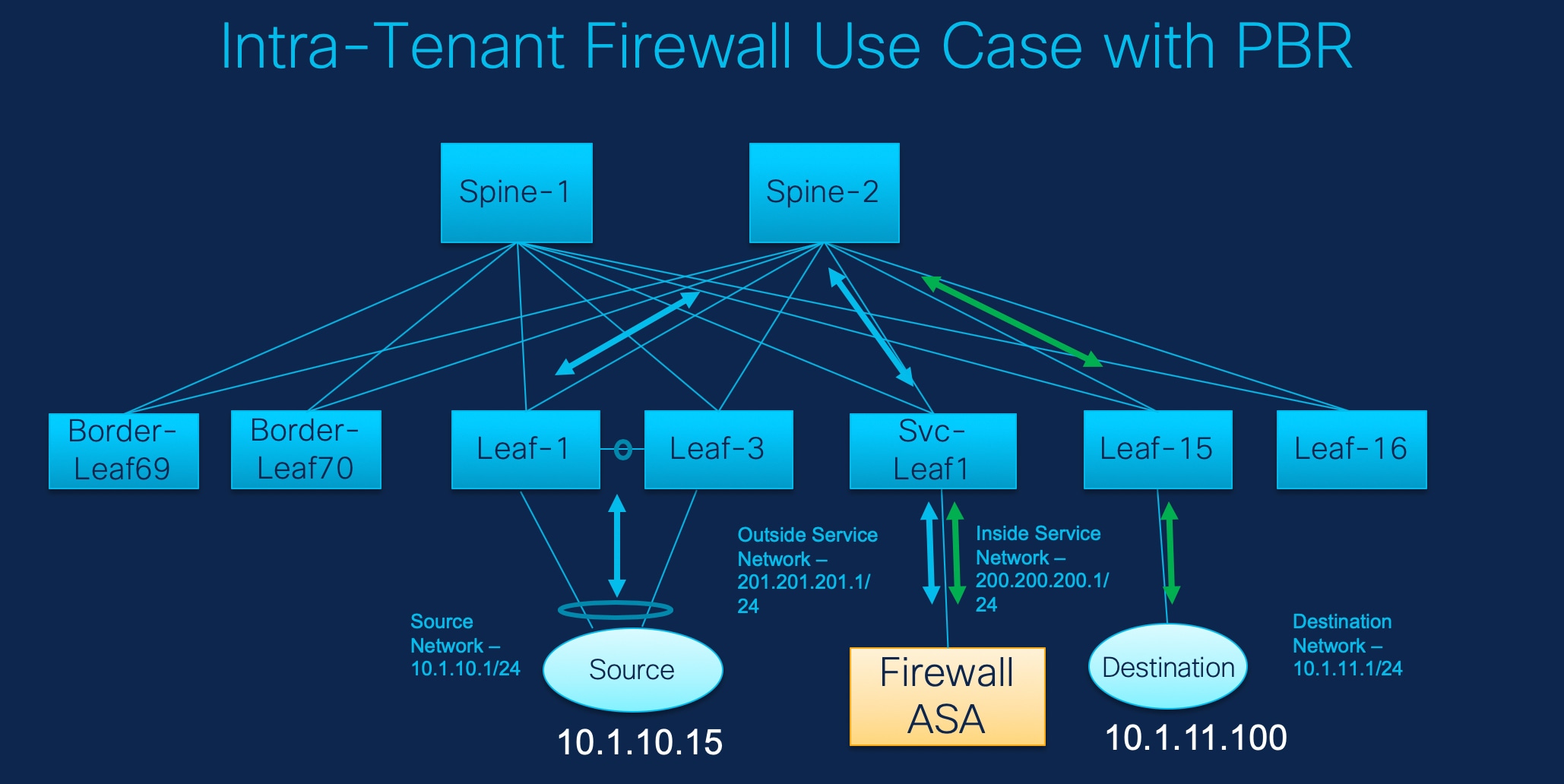
In this topology, Leaf1 and Leaf3 are a vPC pair and they are connected to Source (10.1.10.15) with the Source Network (10.1.10.1/24). The service leaf is connected to the virtual Firewall ASA and Leaf-15 is connected to Destination (10.1.11.100). In this use case, the source network refers to 'client' and the destination refers to 'server'.
Any traffic that is traversing from Source to Destination must go to the outside service network, and the firewall performs its function by allowing or denying traffic. This traffic is then routed to the inside service network and on to the Destination network. Since the topology is stateful, the traffic coming back from the destination to the source follows the same path.
Now, let us see how to perform service redirection in NDFC.

-
This use-case does not cover how to provision the Site_A VXLAN fabric. For information about this topic, refer to the Cisco Nexus Dashboard Fabric Controller for LAN Configuration Guide
-
This use-case does not cover configurations on the service node (firewall or load balancer).
You can navigate to the Services tab by one of the following below mentioned paths:
Manage > Fabrics > Fabric Overview > Services
Manage > Inventory > Switches > Switches Overview > Services
1. Create Service Node
-
Navigate Manage > Fabrics > Fabric Overview > Services.
-
On Services tab, choose Actions > Add.
-
Enter the Service Node Name and specify Firewall in the Service Node Type dropdown box.
The Service Node Name must be unique.
-
From the Form Factor drop-down list, select Virtual.
-
Choose appropriate external fabric from drop-down list, select the external fabric in which the service node (for example, ASA firewall) is located.
Ensure that the service nodes need to belong to the external fabric. This is a prerequisite before creating a service node.
-
Enter the interface name of the service node that connects to the service leaf.
-
Select the attached switch that is the service leaf, and the respective interface on the service leaf.
-
Choose service_link_trunk template. NDFC supports trunk, port channel, and vPC link templates. The available link templates in the Link Template drop-down list are filtered based on the selected Attached Switch Interface type.
-
Specify the General Parameters and Advanced parameters, if required. Some parameters are pre-filled with the default values.
-
Click Save to save the created service node.
2. Create Route Peering
Let us now configure the peering between a service leaf and a service node.
-
Enter the peering name and select Intra-Tenant Firewall from the Deployment drop-down list.
-
Under Inside Network, from the VRF drop-down list, select a VRF that exists and select Inside Network under Network Type.
Enter the name of the Service Network and specify the Vlan ID. You can also click Propose to allow NDFC to fetch the next available VLAN ID from the specified service network VLAN ID range in the fabric settings. The default Service Network Template is Service_Network_Universal.
Under the General Parameters tab, specify the gateway address for the service network. Specify the Next Hop IP Address. This next hop address has to be within the 'inside service network' subnet. Under the Advanced tab, the default Routing Tag value is 12345.
-
Specify the required parameters under Outside Network and specify the Next Hop IP Address for Reverse Traffic. This next hop address for reverse traffic needs to be within the 'outside service network' subnet.
-
Click Save to save the created route peering.
3. Create Service Policy
-
Specify a name for the policy and select the route peering from the Peering Name drop-down list.
-
Select the source and destination VRFs from Source VRF Name and Destination VRF Name drop-down lists. The source and destination VRFs for an intra-tenant firewall deployment have to be the same.
-
Select the source and destination networks from Source Network and Destination Network drop-down lists, or specify the source or destination network that is within the network subnets defined in Fabric Overview > Services window.
-
The next hop and reverse next hop fields are populated based on the values entered while creating the route peering. Select the check box next to Reverse Next Hop IP Address field to enable policy enforcement on reverse traffic.
-
Under the General Parameters tab in the policy template, select ip from Protocol dropdown list, and specify any in Source Port and Destination Port fields.
For ip and icmp protocols, any source and destination port is used for ACL generation. You can also select a different protocol and specify the corresponding source and destination ports. NDFC converts well-known port numbers to match the format required by the switch. For example, you can convert port 80 to 'www'.
-
Under Advanced tab, by default permit is selected for Route Map Action and none is selected for Next Hop Option. You can change these values, and customize the ACL name and route map match sequence number, if required. For more information, refer Templates section in the Layer 4-Layer 7 Service chapter.
-
Click Save to save the created service policy.
This completes procedures to perform and specify the flows for redirection.
5. Deploy Service Policy
-
On Services tab, on the Service Policy window choose the required peering.
-
Choose Actions > Deploy.
The Deploy Service Policy window appears.
-
Click Deploy to confirm deployment.
4. Deploy Route Peering
-
On Services tab, on the Route Peering window choose the required peering.
-
Choose Actions > Deploy.
The Deploy Route Peering window appears.
-
Click Deploy to confirm deployment.
6. View Stats
Now that the respective redirection policies are deployed, the corresponding traffic will be redirected to the firewall.
To visualize this scenario in NDFC, click the service policy, a slide-in pane appears.
You can view the cumulative statistics for a policy in a specified time range.
Statistics are displayed for:
-
Forwarding traffic on the source switch
-
Reversed traffic on the destination switch
-
Traffic in both directions on the service switch
7. View Traffic Flow in Fabric Builder
The service node in the external fabric is attached to the service leaf, and this external fabric shown as a cloud icon in NDFC topology.
-
Click the service leaf, a slide-in pane appears and click Show more flows. You can see the flows that are redirected.
-
Click Details in the Service Flows window to display attachment details.
8. Visualize Redirected Flows to Destination in the Topology window
-
Click Topology and click on leafs to visualize the redirected flows to destination.
-
Select Redirected Flows from the drop-down list.
-
Select a policy from the drop-down list or initiate a search by entering a policy name, source network, and destination network in the search field. The search field is autopopulated based on your input.
The switches, on which the source and destination network is attached and the flows are redirected and highlighted.
-
The service node is shown as connected by a dotted line to the leaf switch on the topology window. Hover over the dotted line to get more information about the interface.
The traffic from Source traverses to the service leaf where the firewall is configured.
Based on firewall rules, traffic is allowed to reach the destination, Leaf 15.
Use Case: Inter-tenant Firewall with eBGP Peering
Refer to figure given below for topology details.
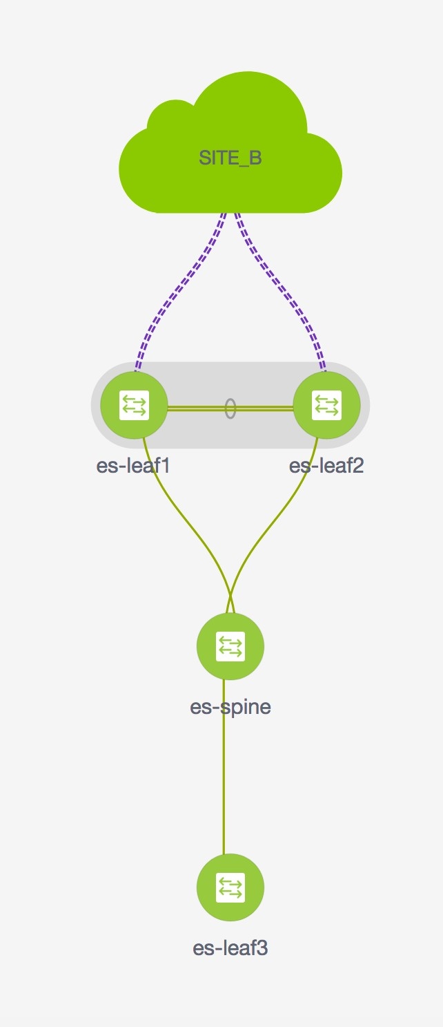
In this topology, es-leaf1 and es-leaf2 are vPC border leaf switches.
Now, let us see how to perform service redirection in NDFC.
This use-case consists of the following steps:
-
As some steps are similar to the steps given in the Intra-tenant Firewall deployment use- case, reference links added to the steps in that use-case.
-
Service policies are not applicable on Inter-tenant firewall deployments.
1. Create Service Node
-
Navigate to Manage > Fabrics > Fabric Overview > Services.
-
On Services tab, choose Actions > Add.
-
Enter service node name, choose Firewall in the Service Node Type dropdown box. The Service Node Name must be unique.
-
From the Form Factor drop-down list, choose Virtual.
-
From the External Fabric drop-down list, choose the external fabric in which the service node (for example, ASA firewall) is located.
Ensure that service nodes need to belong to the external fabric. This is a prerequisite before creating a service node.
-
Enter the interface name of the service node that connects to the service leaf.
-
Select the attached switch that is the service leaf, and the respective interface on the service leaf.
-
Select the service_link_trunk template. NDFC supports trunk, port channel, and vPC link templates. The available link templates in the Link Template drop-down list are filtered based on the selected Attached Switch Interface type.
-
If required, specify General Parameters, and Advanced. Some parameters are pre-filled with default values.
-
Click Save to save the created service node.
For more sample screenshots, refer to 1. Create Service Node section in the Intra-tenant firewall with policy-based routing use case.
2. Create Route Peering
Let us now configure the peering between a service leaf and a service node.
-
Enter the peering name and select Inter-Tenant Firewall from the Deployment drop-down list. From the Peering Option drop-down list, select eBGP Dynamic Peering.
-
Under Inside Network*from the *VRF drop-down list, select a VRF that exists and select Inside Network under Network Type.
Enter the name of Service Network, specify Vlan ID. You can click Propose to allow NDFC to fetch the next available VLAN ID from specified service network VLAN ID range in the fabric settings. The default Service Network Template is Service_Network_Universal.
Under General Parameters tab, specify the gateway address for the service network. Specify Next Hop IP Address. This next hop address has to be within the 'inside service network' subnet. Under the Advanced tab, the default Routing Tag value is 12345.
-
The default Peering Template for eBGP dynamic peering is service_ebgp_route.
Under General Parameters tab, specify Neighbor IPv4 address, Loopback IP address, and vPC Peer’s Loopback IP address. The border switches are a vPC pair.
-
Under the Advanced tab, specify the Local ASN and select the Advertise Host Routes checkbox. This local ASN value is used to override the system ASN on the switch and is required to avoid routing loops.
If the Advertise Host Routes checkbox is selected, the /32 and /128 routes are shown. If this checkbox is not selected, the prefix routes will be shown.
By default, the Enable Interface checkbox is selected.
-
Specify the required parameters under Outside Network and specify the Next Hop IP Address for Reverse Traffic. This next hop address for reverse traffic needs to be within the 'outside service network' subnet.
-
The default Peering Template for eBGP dynamic peering is service_ebgp_route.
Under the General Parameters tab, Neighbor IPv4 address, Loopback IP address, and vPC Peer’s Loopback IP address. The leaf switches are a vPC pair.
-
Under the Advanced tab, specify the Local ASN and select the Advertise Host Routes checkbox. This local ASN value is used to override the system ASN on the switch and is required to avoid routing loops.
If the Advertise Host Routes checkbox is selected, the /32 and /128 routes are advertised. If this checkbox is not selected, the prefix routes will be advertised.
By default, the Enable Interface checkbox is selected.
-
Click Save to save the created route peering.
3. Deploy Route Peering
Refer to 4. Deploy Route Peering in the Intra-Tenant Firewall deployment use-case. Ensure that the InterTenantFW is displayed under Deployment.
The BGP configuration on the vPC border leaf for this use-case is given below.
router bgp 12345
 router-id 10.2.0.1
 address-family l2vpn evpn
  advertise-pip
 neighbor 10.2.0.4
  remote-as 12345
  update-source loopback0
  address-family l2vpn evpn
   send-community
    send-community extended
 vrf myvrf_50001
  address-family ipv4 unicast
   advertise l2vpn evpn
   redistribute direct route-map fabric-rmap-redist-subnet
   maximum-paths ibgp 2
  address-family ipv6 unicast
   advertise l2vpn evpn
   redistribute direct route-map fabric-rmap-redist-subnet
   maximum-paths ibgp 2
  neighbor 192.168.32.254
   remote-as 9876
  local-as 65501 no-prepend replace-as // Note: This configuration corresponds to the Local ASN template parameter value of the service_ebgp_route template of the inside network with VRF myvrf_50001. The no-prepend replace-as keyword is generated along with the local-as command.
  update-source loopback2
  ebgp-multihop 5
  address-family ipv4 unicast
   send-community
   send-community extended
   route-map extcon-rmap-filter-allow-host out
vrf myvrf_50002
 address-family ipv4 unicast
  advertise l2vpn evpn
  redistribute direct route-map fabric-rmap-redist-subnet
  maximum-paths ibgp 2
 address-family ipv6 unicast
  advertise l2vpn evpn
  redistribute direct route-map fabric-rmap-redist-subnet
  maximum-paths ibgp 2
 neighbor 32.32.32.254
  remote-as 9876
  local-as 65502 no-prepend replace-as // Note: This configuration corresponds to the Local ASN template parameter value of the service_ebgp_route template of the outside network with VRF myvrf_50002. The no-prepend replace-as keyword is generated along with the local-as command.
  update-source loopback3
  ebgp-multihop 5
  address-family ipv4 unicast
   send-community
   send-community extended
   route-map extcon-rmap-filter-allow-host out
The loopback interface configuration on the vPC switch es-leaf1 for this use-case is given below. The loopback interfaces in the configuration correspond to the 'Loopback IP' parameter of the service_ebgp_route template. Two loopback interfaces are created automatically on each vPC switch for two separate VRF instances using Loopback IP parameter values that are specified in the service_ebgp_route template.+
interface loopback2
 vrf member myvrf_50001
 ip address 60.1.1.60/32 tag 12345
interface loopback3
 vrf member myvrf_50002
 ip address 61.1.1.60/32 tag 12345
The loopback interface config on vPC peer switch es-leaf2:+
interface loopback2
 vrf member myvrf_50001
 ip address 60.1.1.61/32 tag 12345
interface loopback3
 vrf member myvrf_50002
 ip address 61.1.1.61/32 tag 12345
Use Case: One-arm Load Balancer
Refer figure given below for topology details.
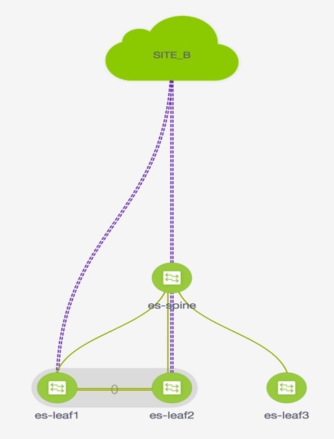
In this topology, es-leaf1 and es-leaf2 are vPC leafs.
Now, let us see how to perform service redirection in NDFC.
You can navigate to the Services tab using of the following paths:
Manage > Fabrics > Fabric Overview > Services
Manage > Inventory > Switches > Switches Overview > Services
This use-case consists of the following steps:
As some steps are similar to the steps given in the Intra-tenant Firewall deployment use-case, reference links provided to the steps in that use-case.
1. Create Service Node
-
Navigate to Manage > Fabrics > Fabric Overview > Services
-
Click the Add icon in the Service Nodes window.
-
Enter the node name and specify Load Balancer in the Type dropdown box. The Service Node Name must be unique.
-
From the Form Factor drop-down list, select Virtual.
-
In the Switch Attachment section, from the External Fabric drop-down list, select the external fabric in which the service node (for example, ASA firewall) is located. Note that the service nodes need to belong to the external fabric. This is a prerequisite before creating a service node.
-
Enter the interface name of the service node that connects to the service leaf.
-
Select the attached switch that is the service leaf, and the respective interface on the service leaf.
-
Select the service_link_trunk template. NDFC supports trunk, port channel, and vPC link templates. The available link templates in the Link Template drop-down list are filtered based on the selected Attached Switch Interface type.
-
Specify General Parameters and Advanced parameters, if required. Some parameters are pre-filled with the default values.
-
Click Save to save the created service node.
For more sample screenshots, refer 1. Create Service Node in the Intra-tenant firewall with policy-based routing use case.
2. Create Route Peering
Let us now configure peering between a service leaf and a service node. In this use-case, we configure static route peering.
-
Enter the peering name and select One-Arm Mode from the Deployment drop-down list. Also, from the Peering Option dropdown list, select Static Peering.
-
Under First Arm, specify the required values. From the VRF dropdown list, select a VRF that exists and select First Arm under Network Type.
-
Enter the name of Service Network and specify Vlan ID. Click Propose to allow NDFC to fetch the next available VLAN ID from the specified service network VLAN ID range in the fabric settings. The default Service Network Template is Service_Network_Universal.
Under the General Parameters tab, specify the gateway address for the service network. Specify the Next Hop IP Address. This next hop address has to be within the first arm’s subnet. Under the Advanced tab, the default Routing Tag value is 12345.
-
The default Peering Template is service_static_route. Add routes, as required, in the Static Routes field.
-
Specify Next Hop IP Address for Reverse Traffic.
-
Click Save to save the created route peering.
3. Create Service Policy
Refer to 3. Create Service Policy in the Intra-Tenant Firewall deployment use-case.
4. Deploy Route Peering
Refer to 4. Deploy Route Peering in the Intra-tenant Firewall deployment use-case. Note that OneArmADC is displayed under Deployment.
5. Deploy Service Policy
Refer to 5. Deploy Service Policy in the Intra-tenant Firewall deployment use-case. However, as there are two servers in this load balancer use-case, two service policies to be defined with each server network.
6. View Stats
Refer to 6. View Stats in the Intra-Tenant Firewall deployment use-case.
7. View Traffic Flow in Fabric Builder
Refer to 7. View Traffic Flow in Fabric Builder in the Intra-Tenant Firewall deployment use-case.
8. Visualize Redirected Flows to Destination in the Topology window
Refer to 8. Visualize Redirected Flows to Destination in the Topology window in the Intra-Tenant Firewall deployment use-case.
The VRF configuration on the service leaf is as given below.
interface Vlan2000
vrf member myvrf_50001
ip policy route-map rm_myvrf_50001
interface Vlan2306
vrf member myvrf_50001
vrf context myvrf_50001
vni 50001
ip route 55.55.55.55/32 192.168.50.254 // Note: This is the static route
rd auto
address-family ipv4 unicast
route-target both auto
route-target both auto evpn
address-family ipv6 unicast
route-target both auto
route-target both auto evpn
router bgp 12345
vrf myvrf_50001
address-family ipv4 unicast
advertise l2vpn evpn
redistribute direct route-map fabric-rmap-redist-subnet
redistribute static route-map fabric-rmap-redist-static
maximum-paths ibgp 2
address-family ipv6 unicast
advertise l2vpn evpn
redistribute direct route-map fabric-rmap-redist-subnet
redistribute static route-map fabric-rmap-redist-static
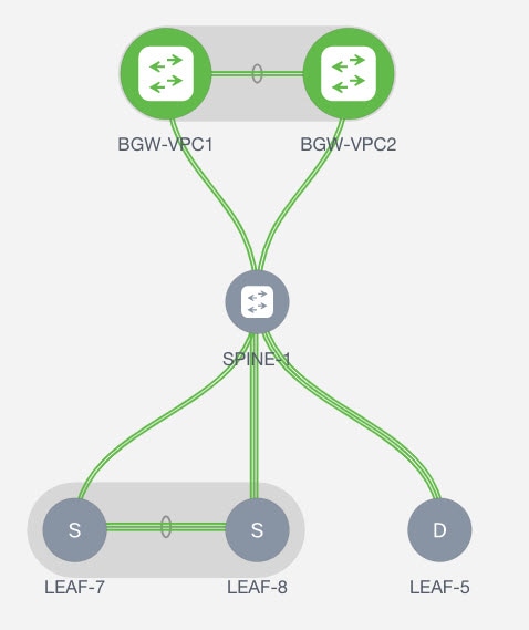
maximum-paths ibgp 2Use Case: One-arm Firewall
Starting from Cisco NDFC Release 12.1.1e, a new deployment One-arm firewall is added.
Refer to the figure for topology details. In this topology, BGW-VPC1 and BGW-VPC2 are vPC Border Gateway which is added as service switches. LEAF-7 and LEAF-8 are vPC leaf switches for which Source (S) network of the redirected flow is attached. LEAF-5 is attached to Destination (D) network of the redirected flow.
Now, let us see how to perform service redirection in NDFC.
You can navigate to the Services tab using one of the following paths:
Manage > Fabrics > Fabric Overview > Services
Manage > Inventory > Switches > Switches Overview > Services
This use-case consists of the following steps:
As some steps are similar to the steps given in the Intra-tenant Firewall deployment use case, reference links added to the steps in that use-case.
1. Create Service Node
-
Navigate to Manage > Fabrics > Fabric Overview > Services
-
Click the Add icon in the Service Nodes window.
-
Enter the node name and specify Firewall in the Type dropdown box. The Service Node Name must be unique.
-
From the Form Factor drop-down list, select Virtual.
-
In the Switch Attachment section, from the External Fabric drop-down list, select the external fabric in which the service node (for example, ASA firewall) is located. Note that the service nodes need to belong to the external fabric. This is a prerequisite before creating a service node.
-
Enter the interface name of the service node that will be connected to the service leaf.
-
Select the attached switch that is the service leaf, and the respective interface on the service leaf.
-
Select the service_link_trunk template. NDFC supports trunk, port channel, and vPC link templates. The available link templates in the Link Template drop-down list are filtered based on the selected Attached Switch Interface type.
-
Specify the General Parameters and Advanced parameters, if required. Some parameters are pre-filled with the default values.
-
Click Save to save the created service node.
For more sample screenshots, refer 1. Create Service Node in the Intra-tenant firewall with policy-based routing use case.
2. Create Route Peering
Let us now configure peering between a service leaf and a service node. In this use-case, we configure static route peering.
-
Enter the peering name and select One-Arm Firewall from the Deployment drop-down list. Also, from the Peering Option dropdown list, choose Static Peering.
You can also choose eBGP Peering option.
-
In Inside Network, specify the required values. From the VRF dropdown list, select a VRF that exists and select Inside Network under Network Type.
-
Enter the name of Service Network, specify Vlan ID, and Network ID. You can click Propose to allow NDFC to fetch the next available Vlan ID from the specified service network Vlan ID range and the next available Network ID from the specified Layer 2 VXLAN VNI range defined in the fabric settings. The default Service Network Template is Service_Network_Universal.
Under the General Parameters tab, specify the gateway address for the service network. Specify the Next Hop IP Address. This next hop address has to be within the inside network’s subnet. Under the Advanced tab, the default Routing Tag value is 12345.
-
The default Peering Template for static peering is service_static_route. Add routes, as required, in the Static Routes field.
-
Click Save to save the created route peering.
3. Create Service Policy
Refer to 3. Create Service Policy in the Intra-Tenant Firewall deployment use-case.
4. Deploy Route Peering
Refer to 4. Deploy Route Peering in the Intra-tenant Firewall deployment use-case.
5. Deploy Service Policy
Refer to 5. Deploy Service Policy in the Intra-tenant Firewall deployment use-case.
6. View Stats
Now that the respective redirection policies are deployed, the corresponding traffic will be redirected to the firewall.
To visualize this scenario in NDFC, click the service policy, a slide-in pane appears.
You can view the cumulative statistics for a policy in a specified time range.
Statistics are displayed for:
-
Forwarding traffic on the source switch
-
Reversed traffic on the destination switch
-
Traffic in both directions on the service switch
8. Visualize Redirected Flows to Destination in the Topology window
Refer to 8. Visualize Redirected Flows to Destination in the Topology window in the Intra-Tenant Firewall deployment use-case.
Copyright
THE SPECIFICATIONS AND INFORMATION REGARDING THE PRODUCTS IN THIS MANUAL ARE SUBJECT TO CHANGE WITHOUT NOTICE. ALL STATEMENTS, INFORMATION, AND RECOMMENDATIONS IN THIS MANUAL ARE BELIEVED TO BE ACCURATE BUT ARE PRESENTED WITHOUT WARRANTY OF ANY KIND, EXPRESS OR IMPLIED. USERS MUST TAKE FULL RESPONSIBILITY FOR THEIR APPLICATION OF ANY PRODUCTS.
THE SOFTWARE LICENSE AND LIMITED WARRANTY FOR THE ACCOMPANYING PRODUCT ARE SET FORTH IN THE INFORMATION PACKET THAT SHIPPED WITH THE PRODUCT AND ARE INCORPORATED HEREIN BY THIS REFERENCE. IF YOU ARE UNABLE TO LOCATE THE SOFTWARE LICENSE OR LIMITED WARRANTY, CONTACT YOUR CISCO REPRESENTATIVE FOR A COPY.
The Cisco implementation of TCP header compression is an adaptation of a program developed by the University of California, Berkeley (UCB) as part of UCB’s public domain version of the UNIX operating system. All rights reserved. Copyright © 1981, Regents of the University of California.
NOTWITHSTANDING ANY OTHER WARRANTY HEREIN, ALL DOCUMENT FILES AND SOFTWARE OF THESE SUPPLIERS ARE PROVIDED “AS IS" WITH ALL FAULTS. CISCO AND THE ABOVE-NAMED SUPPLIERS DISCLAIM ALL WARRANTIES, EXPRESSED OR IMPLIED, INCLUDING, WITHOUT LIMITATION, THOSE OF MERCHANTABILITY, FITNESS FOR A PARTICULAR PURPOSE AND NONINFRINGEMENT OR ARISING FROM A COURSE OF DEALING, USAGE, OR TRADE PRACTICE.
IN NO EVENT SHALL CISCO OR ITS SUPPLIERS BE LIABLE FOR ANY INDIRECT, SPECIAL, CONSEQUENTIAL, OR INCIDENTAL DAMAGES, INCLUDING, WITHOUT LIMITATION, LOST PROFITS OR LOSS OR DAMAGE TO DATA ARISING OUT OF THE USE OR INABILITY TO USE THIS MANUAL, EVEN IF CISCO OR ITS SUPPLIERS HAVE BEEN ADVISED OF THE POSSIBILITY OF SUCH DAMAGES.
Any Internet Protocol (IP) addresses and phone numbers used in this document are not intended to be actual addresses and phone numbers. Any examples, command display output, network topology diagrams, and other figures included in the document are shown for illustrative purposes only. Any use of actual IP addresses or phone numbers in illustrative content is unintentional and coincidental.
The documentation set for this product strives to use bias-free language. For the purposes of this documentation set, bias-free is defined as language that does not imply discrimination based on age, disability, gender, racial identity, ethnic identity, sexual orientation, socioeconomic status, and intersectionality. Exceptions may be present in the documentation due to language that is hardcoded in the user interfaces of the product software, language used based on RFP documentation, or language that is used by a referenced third-party product.
Cisco and the Cisco logo are trademarks or registered trademarks of Cisco and/or its affiliates in the U.S. and other countries. To view a list of Cisco trademarks, go to this URL: http://www.cisco.com/go/trademarks. Third-party trademarks mentioned are the property of their respective owners. The use of the word partner does not imply a partnership relationship between Cisco and any other company. (1110R)
© 2017-2024 Cisco Systems, Inc. All rights reserved.