
New and Changed Information
The following table provides an overview of the significant changes up to this current release. The table does not provide an exhaustive list of all changes or of the new features up to this release.
| Release Version | Feature | Description |
|---|---|---|
|
NDFC release 12.1.3 |
Reorganized content |
Content within this document was originally provided in the Cisco NDFC-Fabric Controller Configuration Guide or the Cisco NDFC-SAN Controller Configuration Guide. Beginning with release 12.1.3, this content is now provided solely in this document and is no longer provided in those documents. |
Inband Management in External Fabrics and Classic LAN Fabrics
Inband Management
Cisco Nexus devices have dedicated out-of-band (OOB) management ports (mgmt0) to manage devices via telnet or SSH connections.
Now you can manage Cisco Nexus devices via Inband using front panel ports either by assigning management IP addresses on one of the ports or using loopback or SVI. By default, (mgmt0) interface is part of management VRF.
In NDFC by default, VRF is used for Inband management, you can use other defined VRFs for inband management for nexus devices. Inband Management is the ability to administer a network through LAN connection.
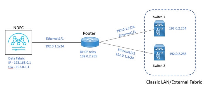
You can import or discover switches with inband connectivity for External and Classic LAN fabrics in Brownfield deployments only. Enable inband management per fabric, while configuring or editing the Fabric settings. You cannot import or discover switches with inband connectivity using POAP.
After configuration, the Fabric tries to discover switches based on the VRF of the inband management. The fabric template determines the VRF of the inband switch using seed IP. If there are multiple VRFs for the same seed IP, then no intent will be learned for seed interfaces. You must create intent or configuration manually.
After configuring or editing the Fabric settings, you must Deploy Config. You cannot change the Inband Mgmt settings after you import inband managed switches to the Fabric. If you uncheck the check box, the following error message is generated.
Inband IP <<IP Address>> cannot be used to import the switch,
please enable Inband Mgmt in fabric settings and retry.
After the switches are imported to the Fabric, you must manage the interfaces to create intent. Create the intent for the interfaces that you are importing the switch. Edit\update the Interface configuration. When you try to change the Interface IP, for this inband managed switch, an error message is generated:
Interface <<interface_name>> is used as seed or next-hop egress interface
for switch import in inband mode.
IP/Netmask Length/VRF changes are not allowed for this interface.
While managing the interfaces, for switches imported using inband management, you cannot change the seed IP for the switch. The following error will be generated:
<<switch-name>>: Mgmt0 IP Address (<ip-address>) cannot be changed,
when is it used as seed IP to discover the switch.
Create a policy for next-hop interfaces. Routes to Cisco Nexus Dashboard Fabric Controller from 3rd party devices can contain multiple interfaces, which are known as ECMP routes. Find the next-hop interface and create an intent for the switch. Interface IP and VRF changes are not allowed.
If inband management is enabled, during Image management, the data interface of nexus dashboard is used to copy images on the switch, in ISSU, EPLD, RPM & SMU installation flows.
If you import the switches using inband connectivity in the fabric and later disable the inband Mgmt in the Fabric settings after deployment, the following error message is generated:
The fabric <<fabric name>> was updated with below message:
Fabric Settings cannot be changed for Inband Mgmt when switches are already imported using inband Ip.
Please remove the existing switches imported using Inband IP from the fabric, then change the Fabric Settings.
However, the same fabric can contain switches imported using both inband and out-of-band connectivity.
Prerequisites
The following are the prerequisites for using Inband Management:
-
Configure appropriate Data Network Routes for reachability to the switch Inband interfaces on Cisco Nexus Dashboard. On Nexus Dashboard, choose Admin Console > Infrastructure > Cluster Configuration. On General tab, enter route IP addresses.
-
On NDFC Web UI, navigate to Server settings > Admin and choose Data from LAN Device Management Connectivity drop-down list to manage Data Center VXLAN EVPN fabrics through inband management, or an error message is displayed. If you choose Data, ensure that the required 'Data Service IPs' are available in the Nexus Dashboard External Service Pools tab.

When server settings changed from Data to Management or vice-versa, allow some time for syslog or poap functionalities to be online and ensure that the IP addresses in Cluster configuration are moved to the appropriate pool.
Guidelines and Limitations
The following are the guidelines and limitations for Inband Management:
-
Both Inband and out-of-band switches in the same fabric is not supported.
-
When you add switches to fabric, ensure that the switches are not in maintenance mode.
Inband POAP Management in External Fabrics and Classic LAN Fabrics
Inband POAP
Power On Auto Provisioning (POAP) automates the process of upgrading software images and installing configuration files on devices that are deployed on the network for the first time. POAP allows devices to bring up without performing any manual configuration.
When a POAP feature enabled device boots and does not find the startup configuration, the device enters POAP mode, locates a DHCP server, and bootstraps itself with its interface IP address, gateway, and DNS server IP addresses. The device obtains the IP address of a TFTP server and downloads a configuration script that enables the switch to download and install the appropriate software image and configuration file.
By using the POAP (Power On Auto Provisioning) feature of Nexus switches, Cisco NDFC (Nexus Dashboard Fabric Controller) can automate the deployment of new datacenters reducing overall time and effort.
Starting NDFC 12.1.1e, External Fabrics and Classic LAN fabrics support adding switches through POAP from inband interfaces.
The Inband POAP is supported for all the roles for fabrics with External and Classic LAN templates.
Prerequisites
The following are the prerequisites for using Inband poap:
-
Configure appropriate Data Network Routes for reachability to the switch Inband interfaces on Cisco Nexus Dashboard. On Nexus Dashboard, choose Admin Console > Infrastructure > Cluster Configuration. On General tab, enter route IP addresses.
-
On NDFC Web UI, navigate to Server settings > Admin and choose Data from LAN Device Management Connectivity drop-down list to manage Data Center VXLAN EVPN fabrics through inband management, or an error message is displayed. If you choose Data, ensure that the required 'Data Service IPs' are available in the Nexus Dashboard External Service Pools tab.
When server settings changed from Data to Management or vice-versa, allow some time for syslog or poap functionalities to be online and ensure that the IP addresses in Cluster configuration are moved to the appropriate pool.
-
Inband POAP on Bootstrap tab is supported only when Inband Management is enabled on Advanced tab in the Fabric settings.
Each subnet for the defined DHCP subnet scope that is mentioned in fabric settings must have a valid route for reverse traffic.
Ensure that the DHCP relay functionality is set on intermediate routers.
Guidelines and Limitations
The following are the guidelines and limitations for Inband POAP:
-
Inband POAP is supported for NX-OS switches only.
-
You can enable Inband POAP with NDFC as a Local DHCP Server or on External DHCP Servers.
-
Inband POAP supports Multi Subnet scope.
-
Inband POAP requires the external router connected seed switches to have the following capabilities:
-
DHCP relay functionality
-
eBGP peering
-
Enabling Inband Management and POAP on External Fabrics and Classic LAN Fabrics
To enable Inband POAP on a fabric, perform the following steps:
-
On the Advanced tab, check Inband Mgmt check box.
-
On Bootstrap tab, do the following:
-
Check Enable Bootstrap check box.
-
Check Enable Local DHCP Server check box and enter appropriate IP addresses in the required fields.
-
Adding Switches
To add or discover switches through Inband POAP, you must follow below steps:
-
Pre-provisioning Switches to a Fabric
-
Add an Interface
-
Add a policy to fabric
-
Import switches using Bootstrap Mechanism
Pre-Provisioning Switches to a Fabric
To add switches to fabric, perform the following steps:
-
On Fabric window, double-click on appropriate fabric and navigate to Fabric Overview window.
-
Navigate to Switches tab and click Actions > Add Switches.
The Add Switches window appears.
-
Choose Pre-provision radio button.
-
Click Actions and add switches.
You can add switches one at a time using the Add option or add multiple switches at the same time using the Import option.
If you use the Add option, ensure you enter all the required details.
-
Choose a switch.
-
Enter the password in the Admin password field.
-
Click Pre-provision.
The pre-provisioned switch is added.
From Cisco NDFC Release 12.1.1e, for pre-provisioned switches dummy values can be added for the serial number. After configuring the network successfully, you can change serial number with the appropriate number of the switch on the Switches tab. See the "Change Serial Number" section in "Performing Actions on Switches" in Add Switches for LAN Operational Mode.
Importing Switches Using Bootstrap Mechanism
Ensure that you have pre-provisioned switches, added interface, and policy before importing the switces using bootstrap mechanism.
To import switches using the bootstrap mechanism.
-
On the Fabric Overview window, click Actions > Add Switches.
The Add Switches window appears.
You can view the existing added switches in the Switches to Bootstrap area.
-
Choose Bootstrap (POAP) radio button and enter a password in Admin password field.
-
Choose the required switches and click Import Selected Switches to bootstrap switches.
Adding an Interface
Add an interface to configure the interface IP addresses on the required switch. To add an interface from the Cisco Nexus Dashboard Fabric Controller Web UI, perform the following steps:
Ensure that you have added the required configurations on the switches such as IP addresses and static routes.
-
On the Fabric Overview window, navigate to the Interface tab.
-
Choose ActionsCreate Interface.
The Create New Interface window appears.
-
Choose Ethernet from the Type drop-down list.
-
Choose the required switch from the Select a device drop-down list and enter a name in the Interface name field.
-
Select the int_routed_host policy from the list of policies .
-
Enter the required configuration details in the Interface IP and IP Netmask Length fields.
-
Enter appropriate details in all the mandatory fields and ensure that you check Enable Interface check box and then click Save.
Adding a Policy to a Fabric
You can add a freeform policy to define external routes in the switch. To add a policy, perform the following steps:
-
On the Fabric Overview window, navigate to the Policies tab and choose Actions > Add Policy.
-
Choose an appropriate switch from the Switch List drop-down list and click Choose Template.
-
On Select Policy Template window, select the switch_freeform template and click Select.
The switch_freeform policy type allows you to add configurations in CLI format.
Recalculating and Deploying Configurations on a Switch
To push pending configurations on to switches, perform the following steps:
-
On Fabric Overview window, navigate to the Switches tab.
You can see that the Config status column displays Pending status.
-
Choose Actions > Recalculate and Deploy.
The Deploy Configuration window appears. It displays the configuration status of the switches. You can also view the pending configurations by clicking the respective link in the Pending Config column.
The Pending Config window appears. The Pending Config tab on this window displays the pending configurations on the switch. The Side-by-Side Comparison tab displays the running configuration and the expected configuration side-by-side.
-
Close the Pending Config window. When all the pending configuration is complete, the Config status column displays In-Sync.
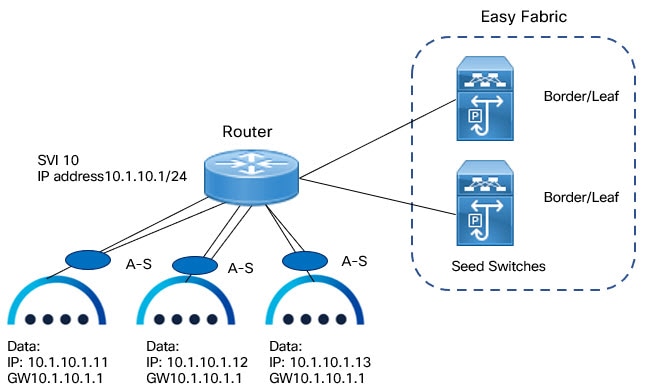
Inband Management and Inband POAP in Data Center VXLAN EVPN Fabrics
You can manage switches with Inband connectivity and Inband POAP for Data Center VXLAN EVPN fabrics. For Inband Management, the Loopback0 interface of the devices is used in the Fabric Settings.
If you want POAP Layer-3 adjacency to switches, you must add Nexus Dashboard Node IP address as DHCP Relay address, perform the following:
-
On NDFC UI, navigate to Settings > Server Settings, click Admin tab. If default value Management is chosen from LAN Device Management Connectivity drop-down list , then DHCP Relay address must be set to the management interface IP (bond1br) in all Nexus Dashboard Nodes.
-
On NDFC UI, navigate to Settings > Server Settings, click Admin tab. If value Data is chosen from LAN Device Management Connectivity drop-down list , then DHCP Relay address must be set to the data interface IP (bond0br) in all Nexus Dashboard Nodes.
You can add switches with Inband Management enabled for Data Center VXLAN EVPN fabrics either in Greenfield or brownfield deployment with Inband POAP or pre-provision and Inband POAP.
-
For Brownfield deployment, check Preserve Config check box.
-
For Greenfield deployment, uncheck Preserve Config check box.
Importing switches with the Preserve Config option enabled will not work under the following conditions:
-
You have more than 100 VRFs and 500 networks, and
-
You are running on either of the following NX-OS images:
-
7.0(3)I7(9)
-
7.0(3)I7(10)
-
In these conditions, the switches will stay in migration mode. Upgrade to NX-OS release 9.x or later to resolve this issue.
The seed switches connect the external routers, and it provides management connectivity to the other switches in the fabric. Switches connected to external routers to provide connectivity to the fabrics are termed as seed switches. The interfaces on the seed switches which connects to the external routers are termed as bootstrap interfaces.
Prerequisites for Inband Management
On NDFC Web UI, navigate to Server settings > Admin and choose Data from LAN Device Management Connectivity to manage Data Center VXLAN EVPN fabrics through Inband management. If you choose Data, ensure that the required Data Service IPs are available in the Nexus Dashboard External Service Pools tab.
When server settings changed from Data to Management or vice-versa, allow some time for syslog or poap functionalities to be online and ensure that the IP addresses in Cluster configuration are moved to the appropriate pool.
This server setting is required for both Inband and out-of-band connectivity. Configure below static routes over data interface in Cisco Nexus Dashboard:
Enter static routes IP address required for external route and route over data interface in Cisco Nexus Dashboard.
Inband POAP requires the external router IP address connected to the seed switches to have the following capabilities:
-
Routes for External router
-
Route for Routing Loopback subnet range for Data Center VXLAN EVPN fabric
-
Route for Underlay Routing subnet range for Data Center VXLAN EVPN fabric
Inband POAP requires the external router connected seed switches to have the following capabilities:
-
DHCP relay functionality
-
eBGP peering
To add switches for Inband Management and Inband POAP, see the section "Discovering New Switches" in Add Switches for LAN Operational Mode.
Guidelines and Limitations
The following are the guidelines and limitations for Inband Management:
-
Ensure that the Inband Management is enabled for Inband interface. Both Inband and out-of-band switches for a same fabric is not supported.
-
It is supported only for IPv4 underlay and OSPF routing protocol.
-
You can change switch management from Inband to out-of-band and conversely after creating a fabric.
-
For the Inband managed switches, the following roles are supported:
-
Spine
-
Leaf
-
Border
-
Border Spine
-
Border Gateway
-
Border Gateway Spine
-
-
Inband management is supported for both numbered and unnumbered fabric interface numbering
-
Ensure that the same role switches are assigned as seed switches. If spine role switch is assigned as a seed switch, all the spine role switches in that fabric must be assigned as seed switches. It is recommended to assign switch as seed switches.
-
When you add switches to fabric, ensure that the switches are not in maintenance mode.
-
You can add switches in Brownfield deployment (check Preserve Config check box) only when the fabric is created. To add more switches, use Inband POAP with import switches option.
-
Set vPC Peer Keep Alive option to loopback if the vPC switches mgmt0 interfaces are not configured.
The following are the guidelines and limitations for Inband POAP:
-
Inband POAP for a fabric can be enabled only if Inband Management is enabled.
-
Inband POAP requires the fabric or core facing interfaces to be cabled consistently for seed switches and spine switches.
-
All spine switches in fabric must use same set of fabric interface numbers.
-
If a fabric has set of leaf switches which are seed switches, then the switches must use same fabric interface number.
-
The seed switches must have eBGP peering with the external router. Therefore, the external router must have the required eBGP route peering capabilities and display the configuration for External router for DHCP relay and Static routes configured for the Subnets used in Data Center VXLAN EVPN fabrics.
-
DHCP relay must be configured on external routers interface which connects the seed switch in Inband interfaces. Ensure that the DHCP relay destination configured is same for all cluster node data interface on Cisco Nexus Dashboard.
-
DHCP server can be internal NDFC or the external server.
Enabling Inband POAP on Data Center VXLAN EVPN Fabrics
To enable Inband POAP on Data Center VXLAN EVPN fabrics, perform the following steps:
-
On the Manageability tab check Inband Management check box.
-
On Bootstrap tab, do the following:
-
Check Enable Bootstrap check box.
-
Check Enable Local DHCP Server checkbox to assign NDFC as DHCP Server and enter the DHCP scopes for all the fabric seed switches bootstrap interfaces.
If you choose Enable Local DHCP Server, and choose unnumbered in Fabric Interface Numbering drop-down list in the General Parameters tab, add details for:
-
Bootstrap Seed Switch Loopback Interface ID
-
Switch Loopback DHCP Scope Start Address
-
Switch Loopback DHCP Scope End Address
-
-
Check External DHCP Server IP Addresses check box to provide connectivity to NDFC from the external router.
If you choose External DHCP Server IP Addresses, you can add a maximum of three IPv4 addresses with a comma separated list.
To have eBGP peering between seeds and an external router, add bootstrap seed switch loopback interface IP address, this IP must be a subset of the loopback id range.
-
Enter Seed Switch interface in Seed Switch Fabric Interfaces text field.
-
Enter Spine Switch interface in Spine Switch Fabric Interfaces text field.
If the Spine switches are the seed switches, then the lists must be consistent in Seed Switch Fabric Interfaces text field.
-
-
For fabrics with unnumbered interface, do the following:
-
On General Parameters, choose unnumbered from Fabric Interface Numbering drop-down list.
-
On Bootstrap tab:
Bootstrap Seed Switch Loopback Interface ID the loopback ID is the default router IP for the fabric. This loopback ID must not overlap with any of the existing fabric loopback IDs.
Switch Loopback DHCP Scope Start Address this IP address is start address of the DHCP pool of the routing loopback addresses range to assign to the bootstrapping switch. This IP address must not overlap with any of the existing IP addresses of Underlay Routing Loopback IP Range.
Switch Loopback DHCP Scope End Address is the end address of the DHCP pool.
-
Importing Switches to Brownfield Deployment
Make sure that you follow prerequisites procedure before adding switches.
-
Create a fabric using the Data Center VXLAN EVPN template. For instructions, see the section "Creating a VXLAN EVPN Fabric Using the Data Center VXLAN EVPN Template" in Data Center VXLAN EVPN.
Ensure that you add switches in the order of Seed switches, Spine switches, and other switches. You can add spine switches as the seed switches.
-
In Brownfield deployment for each fabric, enable Inband Management on the Manageability tab and import the fabric.
-
Add the switches to the fabric with the Preserve Config check box.
-
Enter hostname, Role, enable Seed Switch, and enter appropriate IP address.
-
Enter the IP addresses for all the seed switches, click Import Selected Switches to add them to the fabric.
-
Navigate to Policy tab, click Actions > Add Policy. Choose ext_bgp_neighbor policy so the seed switches establish eBGP peering. Enter the required details, and click Save.
-
Assign the appropriate switch roles.
For more instructions, see the section "Adding Switches Using Bootstrap Mechanism" in Add Switches for LAN Operational Mode.
Pre-provisioning switches through Inband POAP
-
On Switches tab, choose Actions > Add Switches.
The Add Switches window appears.
-
Choose Pre-provision radio button.
-
On Switches to Pre-provision table, click Actions> Add.
The Pre-provision a switch window appears.
-
Enter appropriate details such as Serial Number, Model, IP Address, and click Add.
-
Enter single switch at once and enter the required information. If you have multiple switches.
-
Click Import Switches to Fabric to add switches.
Adding policy for Data Center VXLAN EVPN Fabrics
-
Navigate to LAN > Fabrics window, double-click on appropriate Data Center VXLAN EVPN fabric to add policy.
The Fabric Overview window appears.
-
On Fabric Overview tab, click on Policy tab.
-
Choose appropriate switch from Switch window and click Choose Template.
-
Choose ext_bgp_neighbor policy and click Select.
The Create Policy window appears.
-
Click Actions > Add Policy.
The Create Policy window appears.
-
Enter the appropriate details in the window and click Save.
-
On Fabric Overview window, click Actions > Recalculate and Deploy.
Changing Fabric Management Mode
You can change the fabric from out-of-band to Inband Management and conversely.
-
To change fabric management from out-of-band to Inband Management, perform the following steps:
-
Ensure that you follow prerequisite procedure for Inband Management.
-
In Edit Fabric window, enable Inband Mgmt*on the *Advanced tab and click Save.
-
On Fabric Overview >Switches tab, choose switch and choose Actions >Change Mode, the mode column display Migration.
-
Choose switches. Click Actions > Recalculate and Deploy.
The discovery IP address of the switches changes to the BGP routing loopback IP.
The discovery VRF displays default and discovery interface is updated to BGP routing loopback interface.
An error is generated displaying switch discovery is pending. "The discovery modes for switches have been updated but, discovery may not have completed. Please check to make sure Discovery Status is Ok and retry Recalculate & Deploy".
Click OK.
-
Ensure that the Discovery Status column display status OK, then click Actions > Recalculate and Deploy.
-
-
To change fabric management from Inband Management to out-of-band, perform the following steps:
-
Ensure that you follow prerequisite procedure for out-of-band.
-
Configure out-of-band IP addresses on the switch and this IP must be reachable from NDFC data or Management interface.
-
Choose fabric, click Actions > Edit Fabric.
-
On Advanced tab, uncheck Inband Management check box and click Save.
-
On Fabric Overview >Switches tab, choose switch and choose Actions >Change Mode, the mode column displays Migration.
-
Choose switches. Click Actions > Recalculate and Deploy.
The discovery IP address of the switches will be changed to the mgmt0 IP.
The discovery VRF displays management and discovery interface will be updated to mgmt0.
An error is generated displaying switch discovery is pending. "The discovery modes for switches have been updated but, discovery may not have completed. Please check to make sure that Discovery Status is Ok and retry Recalculate & Deploy".
Click OK.
-
Ensure that the Dcovery Status column displays status OK, then click Actions > Recalculate and Deploy.
-
Secure POAP
When you import switches through bootstrap or POAP in NDFC, it locates a DHCP protocol and bootstraps with interface IP address, gateway, DNS server IP address, and POAP script path. Before NDFC Release 12.1.2e, this was hosted through an HTTP or TFTP server.
From Cisco NDFC Release 12.1.2e, POAP uses an HTTPS server which is a secure protocol to encrypt traffic and validate NDFC for network connection. You must configure Bench Router (BR) to host ®oot Certificate Authority (CA), which is a signed server certificate of POAP server that is hosted on NDFC. In the DHCP response, BR is identified which acts as a trust for a new switch.
Secure POAP is not supported for inband connectivity with bench routers.
See the "CA Certificates" and "Bootstrap Certificates" sections in NX-API and Bootstrap Certificates to upload appropriate certificates on NDFC.
Prerequisites for Secure POAP
-
Secure POAP is supported from Cisco NX-OS 9000 Release 10.2.3 or higher version switches.
-
On NDFC Web UI, navigate to Server Settings, click LAN tab, and choose https or http&https from the drop-down list for Bootstrap Script Download Protocol field.
-
For http or http&https option, you must enter IP address of bench router (BR), port number, and name for certificate bundle in Bench Router URL with port and certificate file name filed. Ensure that the certificates are uploaded on NDFC server for values to autopopulate in this field.
-
By default, for http or http&https option Bench Router URL with port and certificate file name field in the Server setting will be blank. After you install the Root CA Certificate bundle on Bench routers, this field will be autopopulated.
If these fields are autopopulated, with default port number 29151 and URL https://10.10.10.1:29151/PoapCACertBundle.pem, you must configure this URL before you install BR with the Root CA certificate bundle.
-
Make sure that the Fabric is in managed mode before configuring BR.
-
Ensure that you configure DHCP option if the DHCP server is used.
-
You must upload CA signed POAP server certificate on NDFC and upload the corresponding CA certificate bundle for the BR. On NDFC, navigate to Operations > NXAPI Certificates to upload relevant certificates.
Out-of-Band PnP in Campus VXLAN EVPN Fabrics
About Out-of-Band PnP in Campus VXLAN EVPN Fabrics
From Release 12.1.3, NDFC provides support for Out-of-Band (OOB) Plug and Play (PnP) feature which simplifies the process of onboarding new devices with a zero-touch deployment experience. PnP automates the day-zero provisioning of Cisco Catalyst 9000 Series switches using NDFC. With OOB connectivity, the switch provides a separate dedicated network for management traffic over GigabitEthernet 0/0 interface which is always placed in mgmt-vrf.
When a Cisco Catalyst switch powers up and does not find the startup configuration, the device enters PnP mode and sends out a DHCP request, which is served by a DHCP server. The DHCP offer contains the PnP server address and other required configuration for the PnP client. The PnP client on the switch uses this information to connect to the appropriate PnP sever to finish the configuration of the switch. This is a multi-step process, and to provide additional security, the system prompts you to approve the addition of this switch to the fabric. The device then downloads a configuration script and installs the appropriate software image and configuration file.
Enabling Out-of-Band PnP
-
You can use a local or external DHCP Server for IP address assignment.
-
This release only supports DHCP for IPv4.
-
This feature is supported only on Campus VXLAN EVPN fabric.
To enable Out-of-Band PnP in a fabric:
-
When creating a Campus VXLAN EVPN fabric, navigate to the Bootstrap tab of the Create Fabric window.
-
Check the Enable Bootstrap and Enable Local DHCP Server check boxes.
-
Enter the domain name of the DHCP server in the Domain name field.
-
Enter the start address and the end address of your subnet in the DHCP Scope Start Address and DHCP Scope End Address fields.
-
Enter the default gateway for the management VRF on the switch in the Switch Mgmt Default Gateway field.
-
Enter the prefix for the management interface on the switch in the Switch Mgmt IP Subnet Prefix field.
The prefix should be between 8 and 30. The system assigns 24, by default.
-
Enter any other additional configuration CLIs in the Bootstrap Freeform Config field, as required and click Save.
Importing Switches using Bootstrap Method
Ensure you have uploaded the required SSL certificates for the switches. You can use CA-signed certificates or self-signed certificates. Cisco Nexus Dashboard Fabric Controller does not mandate the signing; however, the security guidelines suggest you use the CA-signed certificates.
-
On the Fabric Overview window, choose Actions > Add Switches.
-
In the Switch Addition Mechanism area, click the Bootstrap radio button.
-
Enter the Admin password in the Admin Password field.
The Switches to Bootstrap table lists all the discovered switches.
-
Select the switches you want to add to the fabric and click Import Selected Switches.
Enabling DHCP for PnP
If you are using an external DHCP server and not the NDFC DHCP Server, ensure you perform the following steps on the DHCP server to facilitate PnP server discovery using DHCP.
-
Define the following two DHCP options:
-
pnpserver code 43
-
vrf code 194
-
-
Define option vendor-class-identifier to use the value "ciscopnp".
-
Assign values to option 43 and option 194.
-
Assign option pnpserver "5A1D;K4;B2;I<EXT-IP-NDFC>;J9666";
For <EXT-IP-NDFC>, enter the external POAP IP address on NDFC.
-
Assign option vrf to use the value "Mgmt-vrf".
The following example shows a sample configuration.
option pnpserver code 43 = text;
option vrf code 194 = text;
class "ciscopnp" {
match if option vendor-class-identifier = "ciscopnp";
option vendor-class-identifier "ciscopnp";
option pnpserver "5A1D; K4; B2; I<EXT-IP-NDFC>; J9666";
option vrf "Mgmt-vrf";
option domain-name "cisco.com";
}
NX-API and Bootstrap Certificates
About NX-API and Bootstrap Certificates
Cisco NX-OS switches require an SSL certificate to function in NX-API HTTPS mode. You can generate the SSL certificates and get it signed by your CA. You can install the certificates manually using CLI commands on switch console or use Cisco Nexus Dashboard Fabric Controller to install these on switches.
Cisco Nexus Dashboard Fabric Controller provides a Web UI framework to upload NX-API certificates to Nexus Dashboard Fabric Controller. Later, you can install the certificates on the switches that are managed by Nexus Dashboard Fabric Controller.
For Nexus switches, this feature is supported on switches running Cisco NXOS version 9.2(3) or higher.
Certificate Generation and Management
For each switch, the data center administrator generates an ASCII (base64) encoded certificate. This certificate comprises two files:
-
.key file that contains the private key
-
.crt/.cer/.pem file that contains the certificate
Cisco Nexus Dashboard Fabric Controller also supports a single certificate file that contains an embedded key file, that is, the .crt/.cer/.pem file, which can also contain the contents of the .key file.
Nexus Dashboard Fabric Controller doesn’t support binary encoded certificates, that is, the certificates with the .der extension are not supported. You can protect the key file with a password for encryption. Cisco Nexus Dashboard Fabric Controller does not mandate encryption; however, as this is stored on Nexus Dashboard Fabric Controller, we recommend that you encrypt the key file. Nexus Dashboard Fabric Controller supports AES encryption.
You can either use CA-signed certificates or self-signed certificates. Cisco Nexus Dashboard Fabric Controller does not mandate the signing; however, the security guidelines suggest you use the CA-signed certificates.
You can generate multiple certificates for multiple switches, to upload to Nexus Dashboard Fabric Controller. Ensure that you name the certificates appropriately, to help you choose the switch meant for that certificate.
You can upload one certificate and the corresponding key file, or bulk upload multiple certificates and key files. After the upload is complete, you can view the upload list before installing these on the switches. If a certificate file that contains an embedded key file is uploaded, Nexus Dashboard Fabric Controller derives the key automatically.
Certificate and the key file must have the same filename. For example, if a certificate filename is mycert.pem, the key filename must be mycert.key. If the certificate and key pair filenames are not the same, then Nexus Dashboard Fabric Controller will not be able to install the certificate on the switch.
Cisco Nexus Dashboard Fabric Controller allows you to bulk install the certificates to the switches. Because bulk installation uses the same password, all encrypted keys must be encrypted with the same password. If the password is different for a key, you cannot install the certificate in bulk mode. Bulk mode installation allows you to install encrypted and unencrypted keys certificates together, but all the encrypted keys must have the same password.
When you install a new certificate on the switch, it replaces the existing certificate with the new certificate.
You can install the same certificate on multiple switches; however, you cannot use the bulk upload feature.
Nexus Dashboard Fabric Controller does not enforce the validity of certificates or options provided in it. It is up to you and the requirements on the switch to follow the convention. For example, if a certificate is generated for Switch-1 but it is installed on Switch-2, Nexus Dashboard Fabric Controller doesn’t enforce it; switches may choose to accept or reject a certificate based on the parameters in the certificate.
NX-API Certificate Verification by Cisco Nexus Dashboard Fabric Controller
From release 12.0.1a onwards, Cisco Nexus Dashboard Fabric Controller supports a capability to verify NX-API certificates offered by switches. The NX-API requests done by Cisco Nexus Dashboard Fabric Controller require SSL connection, and switches act like SSL server and offer server certificate as part of SSL negotiations. If provided a corresponding CA certificate, Cisco Nexus Dashboard Fabric Controller can verify it.
By default, NX-API certificate verification is not enabled because it requires all switches in the data center to have the CA-signed certificates installed, and Cisco Nexus Dashboard Fabric Controller is fed all the corresponding CA certificates.
Cisco Nexus Dashboard Fabric Controller NX-API certificate management provides two functionalities named as Switch Certificates and CA Certificates to manage the same.
Switch NXAPI Certificates
Uploading Certificates
To upload the certificates onto Nexus Dashboard Fabric Controller, perform the following steps:
-
Click Upload Certificate to upload the appropriate certificate file.
-
Browse your local directory and choose the certificate key pair that you must upload to Nexus Dashboard Fabric Controller.
You can choose certificates with extension .cer/.crt/.pem + .key file separately.
Cisco Nexus Dashboard Fabric Controller also allows you to upload a single certificate file that contains an embedded key file. The key file is automatically derived after upload.
-
Click Upload to upload the selected files to Nexus Dashboard Fabric Controller.
A successful upload message appears. The uploaded certificates are listed in the table.
The table shows the Status as UPLOADED. If the certificate is uploaded without the key file, the status shows KEY_MISSING.
Assigning Switches and Installing Certificates
To install certificates on the switches using Cisco Nexus Dashboard Fabric Controller Web UI, perform the following steps:
-
Select one or multiple certificates check box.
-
From the Actions drop-down list, select Assign Switch & Install.
-
In the NX API Certificate Credentials field, provide the password which was used to encrypt the key while generating the certificates.
The Password field is mandatory, however, if the keys were not encrypted using a password, any random string you can enter, for example, test, install, and so on. In case of unencrypted files, passwords are not used, but you still need to enter any random string because it is bulk mode.
You can install unencrypted and encrypted keys and a certificate in a single bulk install; however, you must provide the key password used for encrypted keys.
-
For each certificate, click on the Assign arrow and select the switch to associate with the certificate.
-
Click Install Certificates to install all the certificates on their respective switches.
Unlinking and Deleting Certificates
After the certificates are installed on the switch, Nexus Dashboard Fabric Controller cannot uninstall the certificate from Nexus Dashboard Fabric Controller. However, you can always install a new certificate on the switch. The certificates that are not installed on the switches can be deleted. To delete the certificate installed on the switch, you must unlink the certificate from the switch, and then delete it from Nexus Dashboard Fabric Controller.
Unlinking the certificate from the switch does not delete the certificate on the switch. The certificate still exists on the switch. Cisco Nexus Dashboard Fabric Controller cannot delete the certificate on the Switch. To delete certificates from Nexus Dashboard Fabric Controller repository, perform the following steps:
-
Select the certificate(s) that you need to delete.
-
From the Actions drop-down list, select Unlink.
A confirmation message appears.
-
Click OK to unlink the selected certificates from the switches.
The status column shows UPLOADED. The Switch column shows NOT_INSTALLED.
-
Select the certificate that is now unlinked from the Switch.
-
From the Actions drop-down list, select Delete.
The certificate is deleted from Nexus Dashboard Fabric Controller.
CA Certificates
Uploading Certificates
To upload the certificates onto Nexus Dashboard Fabric Controller, perform the following steps:
-
On CA Certificates tab, click Upload Certificate to upload the appropriate license file.
For Secure POAP enabled switches, you must upload Root CA Certificate files. You can upload multiple files at a single instance.
-
Browse your local directory and choose the certificate-key pair to upload.
You can upload certificates with the
.cer/.crt/.pemfile extensions.
Root CA certificates are public certificates and do not contain keys. Switches require these Root CA bundles to verify NDFC POAP/PnP server certificate which is signed by one of the Root CA in the bundle.
-
Click Upload to upload the selected files to Nexus Dashboard Fabric Controller.
A successful upload message appears. The uploaded certificates are listed in the table.
Deleting Certificates
You can delete CA certificates after uploading new certificates. However, NDFC does not assign the Root CA certificate bundle to the Bench Routers. Hence after installing new certificates, ensure that you install the new certificates on the Bench Router (BR).
To install certificate bundles on bootstrap bench router (BR):
-
Choose appropriate certificate, from Actions drop-down list, and choose Install Certificate Bundle to POAP Bench Router (BR).
The Install Certificate Bundle to Bootstrap Bench Router (BR) window appears.
-
Click Assign, and choose relevant switches in the Assign window.
-
Choose Actions > Delete to delete the certificate from Cisco Nexus Dashboard Fabric Controller.
Enabling NX-API Certificate Verification
The NX-API certificate verification is enabled using the toggle button on the CA Certificates page. However, this must be done only after all the switches managed by Cisco Nexus Dashboard Fabric Controller are installed with CA-signed certificates and the corresponding CA Root certificates (one or more) are uploaded to Cisco Nexus Dashboard Fabric Controller. When this is enabled, the Cisco Nexus Dashboard Fabric Controller SSL client starts verifying the certificates that are offered by the switches. If the verification fails, the NX-API calls fail.
-
Verification of the NX-API certificates cannot be enforced per switch; it is for either all or none. Hence, it is important that the verification is enabled only when all the switches have their corresponding CA-signed certificates installed.
-
It is also required that all the CA certificates are installed on the Cisco Nexus Dashboard Fabric Controller.
-
When an NX-API call fails for a given switch because of verification issues, you can use the toggle button to disable enforcement, and all goes back to the previous state without any consequences.
-
Because of the above mentioned points, you must enable the enforcement during a maintenance window.
Bootstrap Certificates
To provision switches using PnP or secure POAP method, ensure that you upload POAP/PnP server certificates on to NDFC. This certificate is offered to Transport Layer Security (TLS) clients (switches).
NDFC supports encrypted certificates only. Ensure that the POAP or PnP server certificate key is encrypted. To upload or delete a Bootstrap Certificate, perform the following steps:
-
Click Upload Certificate to upload the appropriate file.
-
Browse to your local directory and choose the certificate-key pair to upload on Nexus Dashboard Fabric Controller.
You can upload certificates only with file extensions such as
.pem/ .cer/.crt. The key file extension is.key. -
Enter an appropriate password and click Upload to upload the selected files to Nexus Dashboard Fabric Controller.
The successful upload message appears. You can view the uploaded certificates in the table.
-
(Optional) To delete a certificate, choose the required file, and click Delete.
To install a new POAP/PnP server certificate, you must delete the existing certificate and then upload the new POAP/PnP server certificate on NDFC.
Copyright
THE SPECIFICATIONS AND INFORMATION REGARDING THE PRODUCTS IN THIS MANUAL ARE SUBJECT TO CHANGE WITHOUT NOTICE. ALL STATEMENTS, INFORMATION, AND RECOMMENDATIONS IN THIS MANUAL ARE BELIEVED TO BE ACCURATE BUT ARE PRESENTED WITHOUT WARRANTY OF ANY KIND, EXPRESS OR IMPLIED. USERS MUST TAKE FULL RESPONSIBILITY FOR THEIR APPLICATION OF ANY PRODUCTS.
THE SOFTWARE LICENSE AND LIMITED WARRANTY FOR THE ACCOMPANYING PRODUCT ARE SET FORTH IN THE INFORMATION PACKET THAT SHIPPED WITH THE PRODUCT AND ARE INCORPORATED HEREIN BY THIS REFERENCE. IF YOU ARE UNABLE TO LOCATE THE SOFTWARE LICENSE OR LIMITED WARRANTY, CONTACT YOUR CISCO REPRESENTATIVE FOR A COPY.
The Cisco implementation of TCP header compression is an adaptation of a program developed by the University of California, Berkeley (UCB) as part of UCB’s public domain version of the UNIX operating system. All rights reserved. Copyright © 1981, Regents of the University of California.
NOTWITHSTANDING ANY OTHER WARRANTY HEREIN, ALL DOCUMENT FILES AND SOFTWARE OF THESE SUPPLIERS ARE PROVIDED “AS IS" WITH ALL FAULTS. CISCO AND THE ABOVE-NAMED SUPPLIERS DISCLAIM ALL WARRANTIES, EXPRESSED OR IMPLIED, INCLUDING, WITHOUT LIMITATION, THOSE OF MERCHANTABILITY, FITNESS FOR A PARTICULAR PURPOSE AND NONINFRINGEMENT OR ARISING FROM A COURSE OF DEALING, USAGE, OR TRADE PRACTICE.
IN NO EVENT SHALL CISCO OR ITS SUPPLIERS BE LIABLE FOR ANY INDIRECT, SPECIAL, CONSEQUENTIAL, OR INCIDENTAL DAMAGES, INCLUDING, WITHOUT LIMITATION, LOST PROFITS OR LOSS OR DAMAGE TO DATA ARISING OUT OF THE USE OR INABILITY TO USE THIS MANUAL, EVEN IF CISCO OR ITS SUPPLIERS HAVE BEEN ADVISED OF THE POSSIBILITY OF SUCH DAMAGES.
Any Internet Protocol (IP) addresses and phone numbers used in this document are not intended to be actual addresses and phone numbers. Any examples, command display output, network topology diagrams, and other figures included in the document are shown for illustrative purposes only. Any use of actual IP addresses or phone numbers in illustrative content is unintentional and coincidental.
The documentation set for this product strives to use bias-free language. For the purposes of this documentation set, bias-free is defined as language that does not imply discrimination based on age, disability, gender, racial identity, ethnic identity, sexual orientation, socioeconomic status, and intersectionality. Exceptions may be present in the documentation due to language that is hardcoded in the user interfaces of the product software, language used based on RFP documentation, or language that is used by a referenced third-party product.
Cisco and the Cisco logo are trademarks or registered trademarks of Cisco and/or its affiliates in the U.S. and other countries. To view a list of Cisco trademarks, go to this URL: http://www.cisco.com/go/trademarks. Third-party trademarks mentioned are the property of their respective owners. The use of the word partner does not imply a partnership relationship between Cisco and any other company. (1110R)
© 2017-2024 Cisco Systems, Inc. All rights reserved.