
New and Changed Information
The following table provides an overview of the significant changes up to this current release. The table does not provide an exhaustive list of all changes or of the new features up to this release.
| Release Version | Feature | Description |
|---|---|---|
|
NDFC release 12.1.3 |
Reorganized content |
Content within this document was originally provided in the Cisco NDFC-Fabric Controller Configuration Guide or the Cisco NDFC-SAN Controller Configuration Guide. Beginning with release 12.1.3, this content is now provided solely in this document and is no longer provided in those documents. |
Configuring ToR Switches and Deploying Networks in Data Center VXLAN EVPN Fabrics
Overview
The L2 ToRs are considered as replacements for FEXs. In earlier NDFC releases, you can add the Layer 2 ToR switches in an external, and connected to the Leaf switches in the Data Center VXLAN EVPN fabric. The network overlay attachments were managed from the VXLAN EVPN Multi-Site domain as both Data Center VXLAN EVPN fabrics with Spine/Leaf and External fabrics with ToRs were added to an VXLAN EVPN Multi-Site domain. From Cisco NDFC Release 12.1.1e, you can add L2 ToR devices in the same fabric as Spine/Leaf Data Center VXLAN EVPN fabric. This allows a single configuration point for deploying and extending networks for a VXLAN fabric topology with L2 ToRs.

It is not recommended to have a combination of FEX and ToRs in leaf switches due to scale limitation.
An L2 ToR can be physically connected in one of the following ways:
-
Connected to a leaf through a port-channel
-
Connected to a vPC pair of leafs through vPC
-
Connected to one of the leafs in a vPC pair through a port-channel.
A pair of L2 ToRs can be configured in vPC. A ToR vPC pair can only be connected to a leaf vPC pair through back-to-back vPC (also known as Double-Sided vPC).
Description
ToR devices are added to a Data Center VXLAN EVPN in the same way as all other devices.
ToR role must be set on ToR devices before Recalculate and Deploy.
Perform Recalculate and Deploy after any change of ToR pairings/unpairings.
ToRs must be physically connected to the intended parent leaf switches.
vPC Pairing should be done before Leaf-ToR pairings/unpairings.
ToR pairings/unpairings can be done on an individual leaf, or a leaf vPC pair.
Network Overlay association for ToR switches are managed from their parent leaf(s).
ToR ports are shown as additional Ports under leaf.
All intermediate configuration is transparently handled.
Deletion of a leaf will also delete all associated child ToR devices.
A leaf can be connected to many ToRs, but a ToR can be connected to only one leaf or leaf vPC pair.
On the Edit Fabric window, click the Advanced tab and specify the applicable fabric settings.
Spanning-tree Root Bridge Protocol: Choose the protocol from the drop-down list for configuring root bridge. Below are the available protocols:
-
rpvst+: Rapid Per-VLAN Spanning Tree
-
mst: Multiple Spanning Tree
-
unmanaged (default): STP Root not managed by NDFC.
It is recommended to use mst protocol for L2 ToR.
Spanning-tree VLAN Range: Specify the VLAN range. The default value is 1 -3967.
MST Instance Range: Specify the MST instance range. The default value is 0.
STP Bridge Priority: Specify the bridge priority for the spanning tree in increments of 4096.
Limitations
Interface Groups on L2 ToRs are not supported.
Brownfield import on L2 ToRs is not supported.
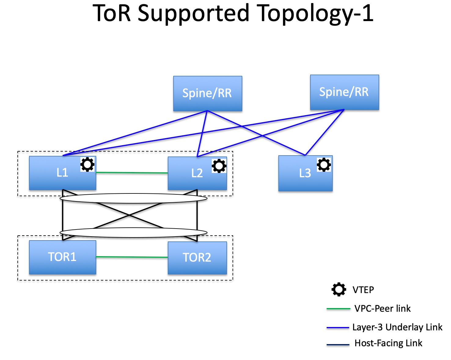
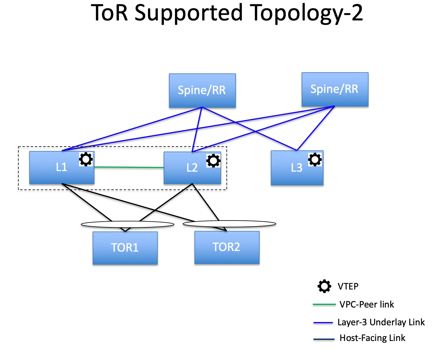
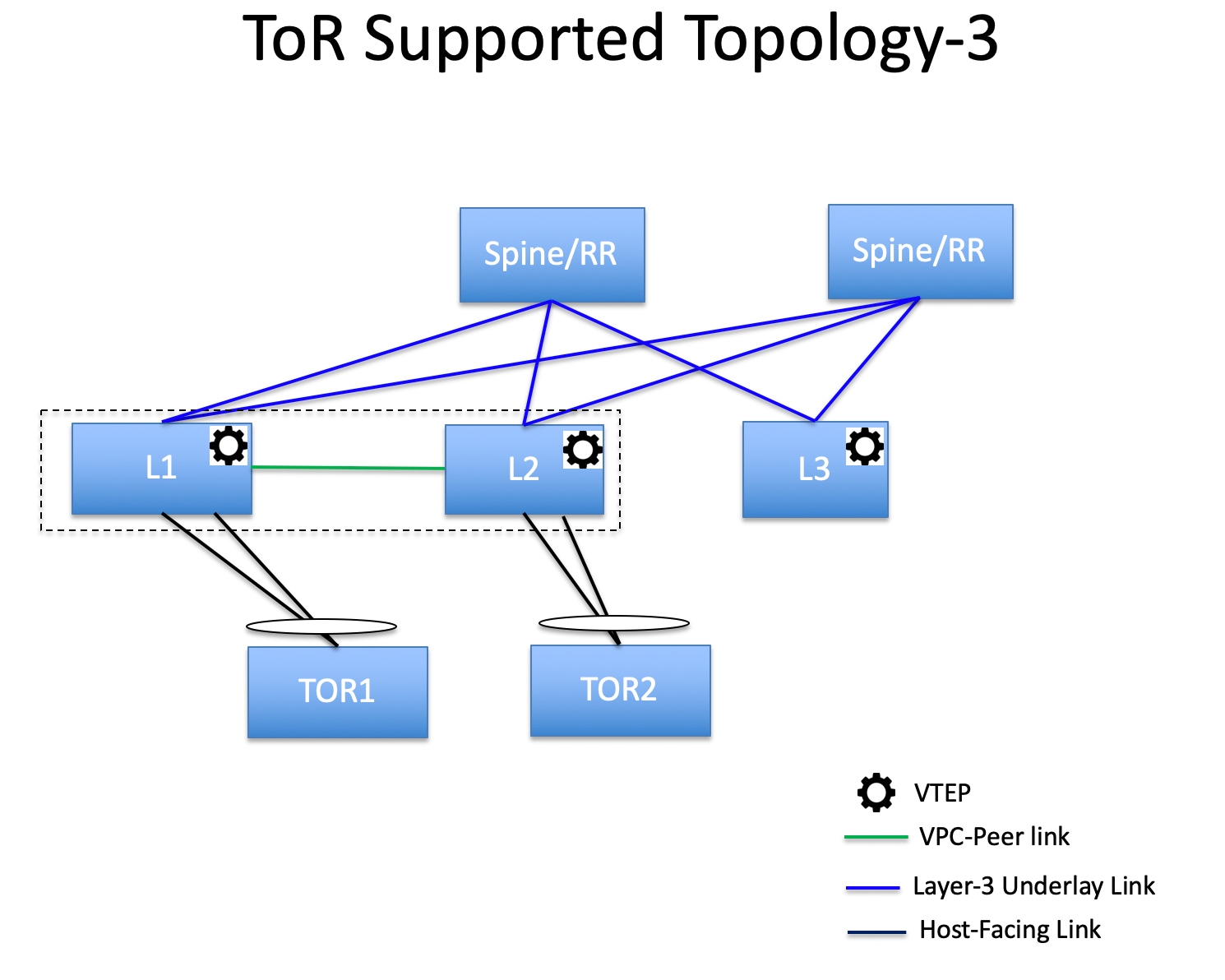
Supported Topologies for ToR Switches
The following topologies with ToR switches are supported:
Only Cisco Nexus 9000 series switches are supported as ToR switches.
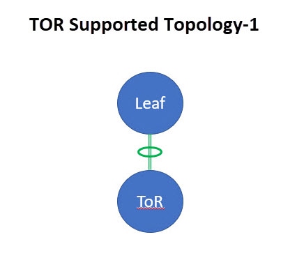
-
ToR switch with port channel directly connected to leaf switch.
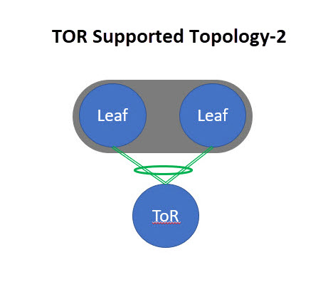
-
ToR switch connected to leaf switches in a vPC pair.
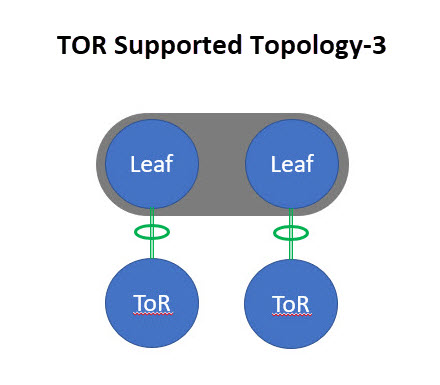
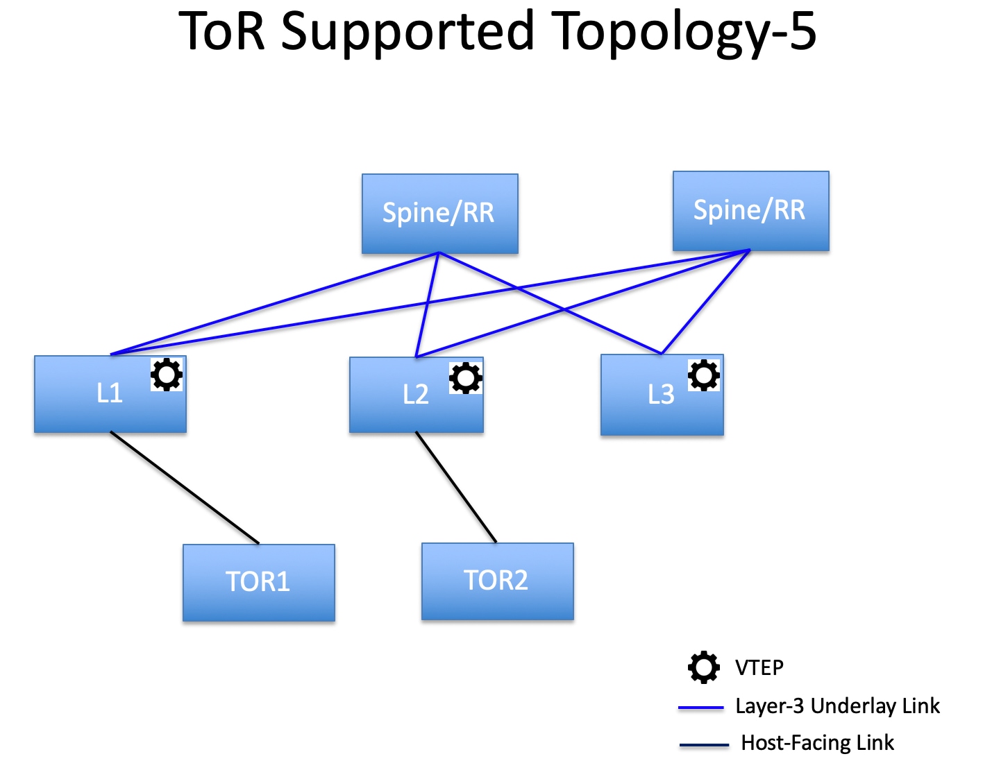
-
ToR switches with port channels connected to leaf switches individually. The leaf switches are in a vPC pair.
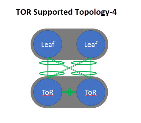
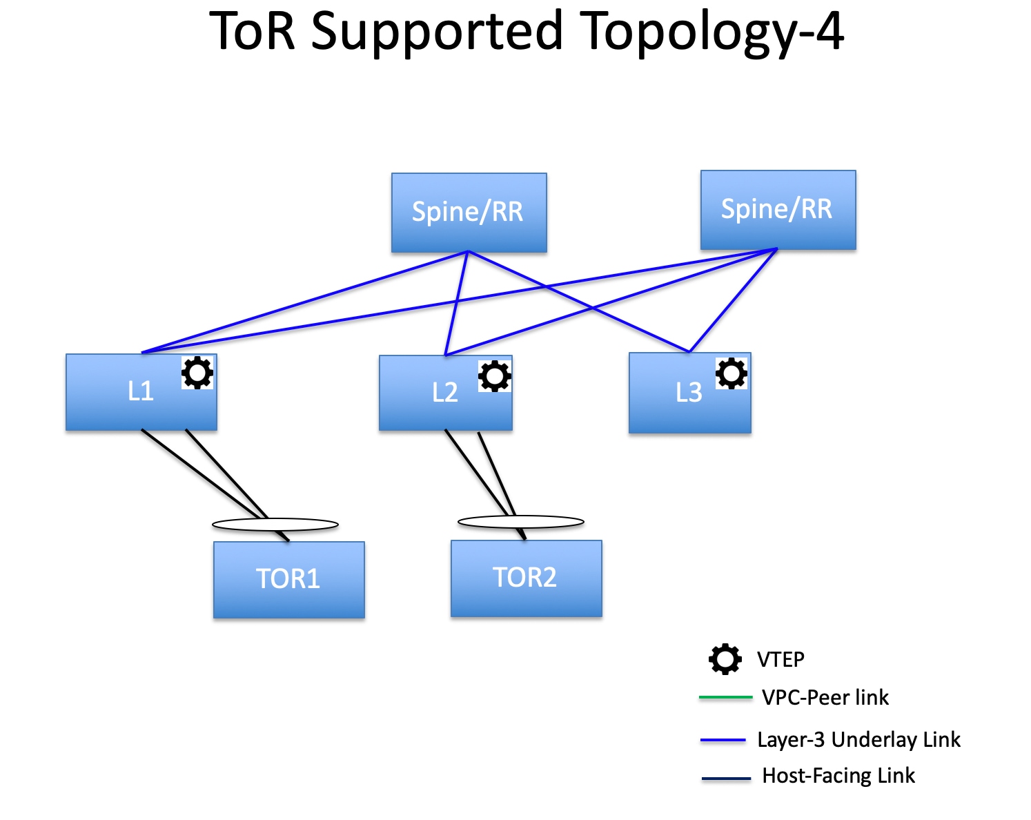
-
ToR switches with back-to-back vPC connections. The leaf switches and ToR switches are both in vPC pairs.
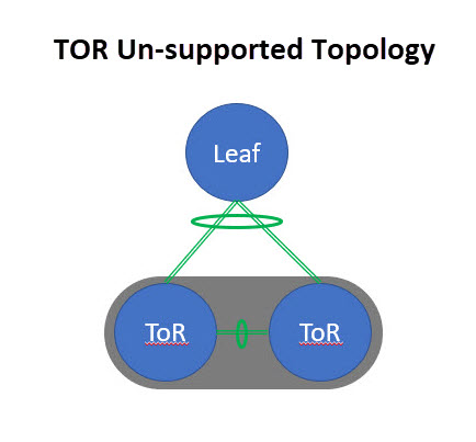
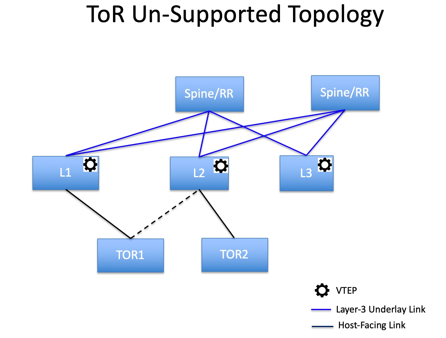
Unsupported Topology for ToR Switches
The following topology with ToR switches are not supported:
ToR vPC pair connected to single leaf switch.
Configuring ToR Switches
Create a fabric with Data Center VXLAN EVPN template and add switches to the fabric, including switches used as ToRs. For more information, see the section "Creating a VXLAN EVPN Fabric Using the Data Center VXLAN EVPN Template" in Data Center VXLAN EVPN. Based on the selection of topology, perform any of the following steps:
-
Perform the following procedure to configure ToR and leaf switch as shown in the ToR Topology-1 and 3, where ToR switch(s) connected to leaf switch(s) through port channel. Leaf switches are already added to the fabric.
-
Add ToR switches to the Data Center VXLAN EVPN fabric and set role as ToR.
-
Select the leaf switch connected to ToR and click on Actions > TOR Pairing.
The TOR Pairing Window appears with the list of ToR switches.
-
Select all the ToR switches connected to this leaf and click Save (NDFC also gives recommendation based on ToR’s connectivity to the leaf).
-
On the Fabric Overview window, click Actions > Recalculate and Deploy.
-
After the configuration deployment is completed in the Deploy Configuration window, click Close.
-
-
Perform the following procedure to configure ToR and leaf switch as shown in the ToR Topology-2 and 4, where ToR switch connected to leaf switch through vPC pair, and back-back vPC connection.
-
Select either of the vPC paired leaf switch and click on Actions > TOR Pairing. For more information, see Creating a vPC setup.
The TOR Pairing Window appears with the list of ToR switches.
-
When the vPC pair of leaf nodes is selected, by default, you must select the required ToR switch(s) in the list.
If you selected either leaf 1 or leaf 2, check the Complete TOR Pairing as VPC Pair check box.
-
Select the ToR switch(es) and click Save.
-
On the Fabric Overview window, click Actions > Recalculate and Deploy.
-
After the configuration deployment is completed in the Deploy Configuration window, click Close.
-
-
Perform the following procedure to un-pair the ToR.
-
Remove the overlay attachment before un-pairing the ToR.
-
On the Fabric Overview window, click the Switches tab.
-
Select any vPC leaf switch and click on Actions > TOR Pairing.
The TOR Pairing window appears.
-
Check the Complete TOR Pairing as VPC Pair check box for topologies-2 and 4 and uncheck the ToR switch to unpair.
-
Click Save.
-
On the Fabric Overview window, click Actions > Recalculate and Deploy.
-
On the Deploy Configuration Window, click Deploy.
-
After the configuration deployment is completed in the Deploy Configuration window, click Close.
-
Deploying Networks on ToR Switches
To deploy networks on ToR switches in the Data Center VXLAN EVPN fabrics, perform the following steps:
-
Choose LAN > Fabrics, then double-click on the Data Center VXLAN EVPN fabric.
-
In the Networks window, select the networks that you want to deploy or create a new network. For information about creating a network, see the section "Creating Network for Standalone Fabrics" in Data Center VXLAN EVPN.
-
On the Fabric Overview window, click Networks > Network Attachments.
-
Select the leaf switches and click on Actions > Edit.
The Edit Network Attachment window appears.
-
On the Edit Network Attachment window, choose Attach.
-
(Optional) Enter the value in the VLAN field.
-
Select interfaces/ports on a leaf switch and/or associated ToR(s) attaching Endpoints or Layer 2 devices and click Save. Therefore, the port channels that are used to connect the ToR(s) toward the leaf node(s) or vPC pair will be automatically updated with the required VLAN deployed in the server interfaces of the ToR switch.
-
Select the leaf switch and click on Actions > Deploy.
Configuring ToR Switches and Deploying Networks in External Fabrics
Overview
NDFC supports the Top-of-Rack (ToR) switches. You can add the Layer 2 ToR switches in an external fabric, and they can be connected to the Leaf switches in the Data Center VXLAN EVPN. Typically, the Leaf and ToR devices are connected with back-to-back vPC connection. For more information, see Supported Topologies for ToR Switches.
Supported Topologies for ToR Switches
The following topologies with ToR switches are supported in NDFC:
Cisco Nexus 7000 Series Switches do not support the ToR switch role in Cisco NDFC.
-
ToR switches with back to back vPC connection to the leaf switches.
-
ToR switches with port channels connected to both the leaf switches. The L1 and L2 switches are connected as a vPC pair.
-
ToR switches with port channels directly connected to the leaf switches. The L1 and L2 switches are connected as a vPC pair.
-
ToR switches with port channels directly connected to the leaf switches. vPC pairs are not configured for the leaf or ToR switches.
-
ToR switches directly connected to the leaf switches. vPC pairs are not configured for the leaf or ToR switches.
Unsupported Topologies for ToR Switches
The following topology with ToR switches is not supported in NDFC:
Configuring ToR Switches
Before you begin, make sure you have an Data Center VXLAN EVPN or create and deploy a new fabric. For more information, see the section "Creating a VXLAN EVPN Fabric Using the Data Center VXLAN EVPN Template" in Data Center VXLAN EVPN.
NDFC supports the trunk_host policies for the ToR switches. Make sure ToR has vPC, port channel or trunk host policy attached on the interfaces connected to Leaf. These policies are used to connect the ToR switches in the external fabric to the Leaf switches in the Data Center VXLAN EVPN.
Procedure
-
Create an external fabric and add two ToR switches. For more information, see the section "Creating an External Fabric" in External Connectivity Network.
The number of ToR switches can be more than two. This procedure shows how to configure ToR switches as shown in the ToR Topology-1, where ToR switches are connected using vPC. The following are the different scenarios for connecting the ToR switches:
-
If vPC is not configured on the ToR switches, then vPC policy need to be applied on ToR facing interfaces if uplinks of these ToR switches are connected to vPC leaf switches.
-
If ToR switches are connected to leaf using port-channel, then port-channel policies need to be applied on the ToR interfaces connected to the leaf switches.
-
If ToR switches are connected to leaf switches as standalone, the trunk policies need to be applied on the TOR interfaces.
-
While creating the external fabric, make sure that the Fabric Monitor Mode check box is not chosen.
-
The two ToR switches must be connected and have same switch role.
-
After adding the ToR switches, make sure that the role for the ToR switches is chosen as ToR.
-
-
Select one of the ToR switch and click on Actions > vPC Pairing.
Choose the second ToR switch as a vPC Peer.
-
Under vPC Pair Template, enter all the relevant details for a vPC connection between both the ToR switches. For more information about fields and their descriptions, see the section "Creating a vPC Setup" in External Connectivity Network.
Step 2, and 3 are required since this example shows the ToR configuration for Topology-1. For Topology 2, 3, 4, and 5, the steps 2 and 3 are not required.
-
On Switch Overview window, click Actions > Recalculate and Deploy.
-
After the configuration is completed in the Config Deployment window, click Close.
-
Create an VXLAN EVPN Multi-Site fabric.
While creating the VXLAN EVPN Multi-Site fabric, under the General tab, choose the ToR Auto-deploy Flag check box. This action enables automatic deployment of the networks and VRFs in the Data Center VXLAN EVPN fabric to the ToR switches in the External Fabric when you click Recalculate and Deploy in the VXLAN EVPN Multi-Site fabric. For more information, see Deploying Networks on ToR Switches.
For information about the remaining tabs and fields, see Creating a VXLAN EVPN Multi-Site Fabric.
-
Open the VXLAN EVPN Multi-Site fabric. Navigate to Child Fabrics and click on Actions to move fabric into VXLAN EVPN Multi-Site. Select the Data Center VXLAN EVPN fabric Actions > Interface.
Choose vPC and enter all the relevant details and click Save.
For more information about the fields in this window, see the section "Adding Interfaces" in Add Interfaces for LAN Operational Mode.
After saving all the information, click Deploy.
Similarly, follow the Steps 9 and 10 to create a vPC on the ToR switch as well.
Deploying Networks on ToR Switches
To deploy networks on ToR switches in the external fabrics, you need to deploy them on the switches in the Data Center VXLAN EVPN through VXLAN EVPN Multi-Site. These switches should be connected to the ToR switches.
Procedure
-
Choose LAN > Fabrics, then double-click on the Data Center VXLAN EVPN fabric.
-
In the Networks window, select the networks that you want to deploy or create a new network. For information about creating a network, see the section "Creating Network for Standalone Fabrics" in Data Center VXLAN EVPN.
-
Select the Network from the Network Attachment window. Click on Actions and Edit. Attach the network and select the appropriate interface/port-channels and then click on Save. These port channels connect the leaf switches to the ToR switches. The networks will be deployed on these port channels.
-
On Fabric Overview window, click Actions > Recalculate and Deploy.
Now the VLANs are deployed on the leaf switches.
-
Navigate to VXLAN EVPN Multi-Site fabric.
-
On Fabric Overview window, click Actions > Recalculate and Deploy.
The networks created and deployed on the leaf switches in the Data Center VXLAN EVPN fabric are also deployed on the ToR switches in the external fabric. This step allows the same VLANs to be configured on the ToR switches that are deployed on the leaf switches in the Step 4.
If VLANs are created on the ToR switches manually using the freeform configs, they are not modified.
Copyright
THE SPECIFICATIONS AND INFORMATION REGARDING THE PRODUCTS IN THIS MANUAL ARE SUBJECT TO CHANGE WITHOUT NOTICE. ALL STATEMENTS, INFORMATION, AND RECOMMENDATIONS IN THIS MANUAL ARE BELIEVED TO BE ACCURATE BUT ARE PRESENTED WITHOUT WARRANTY OF ANY KIND, EXPRESS OR IMPLIED. USERS MUST TAKE FULL RESPONSIBILITY FOR THEIR APPLICATION OF ANY PRODUCTS.
THE SOFTWARE LICENSE AND LIMITED WARRANTY FOR THE ACCOMPANYING PRODUCT ARE SET FORTH IN THE INFORMATION PACKET THAT SHIPPED WITH THE PRODUCT AND ARE INCORPORATED HEREIN BY THIS REFERENCE. IF YOU ARE UNABLE TO LOCATE THE SOFTWARE LICENSE OR LIMITED WARRANTY, CONTACT YOUR CISCO REPRESENTATIVE FOR A COPY.
The Cisco implementation of TCP header compression is an adaptation of a program developed by the University of California, Berkeley (UCB) as part of UCB’s public domain version of the UNIX operating system. All rights reserved. Copyright © 1981, Regents of the University of California.
NOTWITHSTANDING ANY OTHER WARRANTY HEREIN, ALL DOCUMENT FILES AND SOFTWARE OF THESE SUPPLIERS ARE PROVIDED “AS IS" WITH ALL FAULTS. CISCO AND THE ABOVE-NAMED SUPPLIERS DISCLAIM ALL WARRANTIES, EXPRESSED OR IMPLIED, INCLUDING, WITHOUT LIMITATION, THOSE OF MERCHANTABILITY, FITNESS FOR A PARTICULAR PURPOSE AND NONINFRINGEMENT OR ARISING FROM A COURSE OF DEALING, USAGE, OR TRADE PRACTICE.
IN NO EVENT SHALL CISCO OR ITS SUPPLIERS BE LIABLE FOR ANY INDIRECT, SPECIAL, CONSEQUENTIAL, OR INCIDENTAL DAMAGES, INCLUDING, WITHOUT LIMITATION, LOST PROFITS OR LOSS OR DAMAGE TO DATA ARISING OUT OF THE USE OR INABILITY TO USE THIS MANUAL, EVEN IF CISCO OR ITS SUPPLIERS HAVE BEEN ADVISED OF THE POSSIBILITY OF SUCH DAMAGES.
Any Internet Protocol (IP) addresses and phone numbers used in this document are not intended to be actual addresses and phone numbers. Any examples, command display output, network topology diagrams, and other figures included in the document are shown for illustrative purposes only. Any use of actual IP addresses or phone numbers in illustrative content is unintentional and coincidental.
The documentation set for this product strives to use bias-free language. For the purposes of this documentation set, bias-free is defined as language that does not imply discrimination based on age, disability, gender, racial identity, ethnic identity, sexual orientation, socioeconomic status, and intersectionality. Exceptions may be present in the documentation due to language that is hardcoded in the user interfaces of the product software, language used based on RFP documentation, or language that is used by a referenced third-party product.
Cisco and the Cisco logo are trademarks or registered trademarks of Cisco and/or its affiliates in the U.S. and other countries. To view a list of Cisco trademarks, go to this URL: http://www.cisco.com/go/trademarks. Third-party trademarks mentioned are the property of their respective owners. The use of the word partner does not imply a partnership relationship between Cisco and any other company. (1110R)
© 2017-2024 Cisco Systems, Inc. All rights reserved.